Lab 02 Resistor color coding and ohms law
•
19 recomendaciones•37,032 vistas

1. This document describes an experiment to identify resistor color codes and verify Ohm's Law. It includes objectives, equipment, procedures, and questions. 2. The first part explains how to determine a resistor's value and tolerance from its color bands. Tables list the color codes used in 4-band and 5-band resistors. 3. The second part tests Ohm's Law by measuring the current through resistors under different voltages. A circuit is assembled and current is measured both ways through each resistor to verify the relationships defined by Ohm's Law.

Recomendados
Más contenido relacionado
La actualidad más candente
La actualidad más candente (20)
Similar a Lab 02 Resistor color coding and ohms law
Similar a Lab 02 Resistor color coding and ohms law (20)
Más de Hassaan Rahman
Más de Hassaan Rahman (20)
Último
Último (20)
Lab 02 Resistor color coding and ohms law
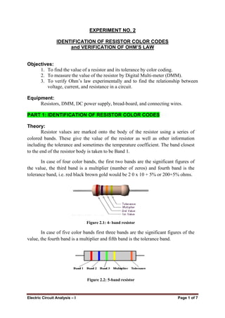
- 1. Electric Circuit Analysis – I Page 1 of 7 EXPERIMENT NO. 2 IDENTIFICATION OF RESISTOR COLOR CODES and VERIFICATION OF OHM’S LAW Objectives: 1. To find the value of a resistor and its tolerance by color coding. 2. To measure the value of the resistor by Digital Multi-meter (DMM). 3. To verify Ohm’s law experimentally and to find the relationship between voltage, current, and resistance in a circuit. Equipment: Resistors, DMM, DC power supply, bread-board, and connecting wires. PART 1: IDENTIFICATION OF RESISTOR COLOR CODES Theory: Resistor values are marked onto the body of the resistor using a series of colored bands. These give the value of the resistor as well as other information including the tolerance and sometimes the temperature coefficient. The band closest to the end of the resistor body is taken to be Band 1. In case of four color bands, the first two bands are the significant figures of the value, the third band is a multiplier (number of zeros) and fourth band is the tolerance band, i.e. red black brown gold would be 2 0 x 10 + 5% or 200+5% ohms. Figure 2.1: 4- band resistor In case of five color bands first three bands are the significant figures of the value, the fourth band is a multiplier and fifth band is the tolerance band. Figure 2.2: 5-band resistor
- 2. Electric Circuit Analysis – I Page 2 of 7 In case of six color bands the sixth band is the temperature coefficient band. Following tables give the values allocated to different colors to find the value of a resistor through the color bands it has on it. 4-band Resistor Color Codes: Figure 2.3: 4- band resistor Color Band 1 Band 2 Multiplier Black 0 0 1 Brown 1 1 10 Red 2 2 100 Orange 3 3 1000 Yellow 4 4 10000 Green 5 5 100000 Blue 6 6 1000000 Violet 7 7 Grey 8 8 White 9 9
- 3. Electric Circuit Analysis – I Page 3 of 7 5-band Resistor Color Codes: Figure 2.4: 5-band resistor Color Band 1 Band 2 Band 3 Multiplier Black 0 0 0 1 Brown 1 1 1 10 Red 2 2 2 100 Orange 3 3 3 1000 Yellow 4 4 4 10000 Green 5 5 5 100000 Blue 6 6 6 1000000 Violet 7 7 7 10-1 Grey 8 8 8 10-2 White 9 9 9 The resistance value of the resistor is not the only thing to consider when selecting a resistor for use in a circuit. The "tolerance" and the electric power ratings of the resistor are also important. The tolerance of a resistor denotes how close it is to the actual rated resistance value. For example, a ±5% tolerance would indicate a resistor that is within ±5% of the specified resistance value. The power rating indicates how much power the resistor can safely tolerate. The maximum rated power of the resistor is specified in Watts. Power is calculated using the square of the current ( I2 ) x the resistance value ( R ) of the resistor. If the maximum rating of the resistor is exceeded, it will become extremely hot and even burn. Resistors in electronic circuits
- 4. Electric Circuit Analysis – I Page 4 of 7 are typically rated 1/8W, 1/4W, and 1/2W. 1/8W is almost always used in signal circuit applications. Tolerance: Color: None Silver Gold Red Brown Tolerance: 20% 10% 5% 2% 1% Example: Figure 2.5: Example on how to read the resistor value through color codes
- 5. Electric Circuit Analysis – I Page 5 of 7 Questions: 1. What is the value of resistor having colors red, red, yellow and gold? 2. What does “short circuit” mean? 3. What does “open circuit” mean? Lab Exercise: Select ten resistors (5% tolerance) between 1Ω and 1MΩ. Verify the value of resistance and tolerance of resistors using color codes, and complete the following table: No. Value of Resistance through color codes (Ω) Tolerance (%) Range (Ω) Value of Resistance measured by the DMM (Ω) Error (%) 1. 2. 3. 4. 5. 6. 7. 8. 9. 10.
- 6. Electric Circuit Analysis – I Page 6 of 7 PART 2: VERIFICATION OF OHM’S LAW Theory: Ohm’s law states that “the voltage v (or potential difference) across a resistor is directly proportional to the current i flowing through it.” As the current increases the voltage drop also increases provided that the resistance is kept constant; and the current decreases as the resistance increases provided that the voltage across the resistor terminals remains the same. Mathematically, v i∝ v iR= where R is the constant of proportionality and is the resistance of the resistor element. Material that obeys Ohm's Law is called "ohmic" or "linear" because the potential difference (or voltage) across its terminals varies linearly with the value of current flowing through it. Lab Exercise: Safety Precautions Look at each exercise carefully before connecting the circuits. Make sure all power is off before connecting or disconnecting components. Ask your TA to check the circuit before turning on the power. When measuring voltage or current, make sure the DMM is correctly set for what you need to measure. 1. Assemble on the bread-board the circuit shown in Figure 2.6 using the same voltage setting on the power supply and the same resistor as shown. 2. Set the multi-meter to measure dc current, make sure that the leads are correctly set for current measurement. 3. Measure the current flowing through the resistor. Does this value agree with the calculations using Ohm's Law v i R ⎛ ⎞ =⎜ ⎟ ⎝ ⎠ ? 4. Measure the current flowing through the resistor in the opposite direction. This is done by reversing the leads of the ammeter. Does this value agree with the calculations using Ohm's Law v i R ⎛ ⎞ =⎜ ⎟ ⎝ ⎠ ?
- 7. Electric Circuit Analysis – I Page 7 of 7 Figure 2.6: a simple resistive circuit to verify Ohm’s law 5. Complete the following table. Draw a graph between the measured voltage and current for each value of resistance; and find out the approximate value of resistance through the graphs drawn. V (volts) R = ____ Ω R = ____ Ω R = ____ Ω I (mA) Observed I (mA) Calculated I (mA) Observed I (mA) Calculated I (mA) Observed I (mA) Calculated 0.5 1.0 1.5 2.0 2.5 3.0 3.5 4.0 4.5 5.0 V 10V R 1kΩ