1. l!!!!!a
O0
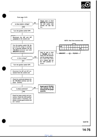
From page 14-74
,&,
Repair open or short
BLKlYEL wire between
the A23 andlor A24
terminals and dash fuse
box.
Reconnect the 26P and 22P
conectors to the control unit.
NOTE: View from terminal side.
I
Turn the ignition switch ON. Be
sure that the voltage is available
for 2 seconds between the A8
(YELIBLK) t e r m i n a l a n d A 2 5
(BRN/WHT) terminal.
Is there voltage?
NO
c
Check for open or short
in YELlBLK wire between the A8 terminal
and the gauge assembly. If wire is OK, check
the D indicator light and
the shift position indicator.
Turn the ignition switch OFF.
Disconnect the 26P and 22P connectors from the control unit.
Check for continuity between the
A8 (YELIBLK) terminal and the
gauge assembly.
Check for loose control unit connectors. Check the shift position
console switch. If necessary, substitute a known-good control unit
and recheck.
kont’d)
vnx.su
2. -1rroubleshooting
r
Flowchart (ckt’d)
,,...I
NOTE: View from terminal side.
D indicator light is on steady, not
bknkmg whenever the lgnitton
til
Measure voltage between the A8
/
YElJBLK
Replace the A/l control
unit.
Is there voltage?
I
YES
I
Measure voltage between the
YELIBLK wire at the gauge assembly and body ground.
Is there voltage?
NO
Replace faulty shift position indicator.
YES
14-76
vnx.su
3. Inspection of the A/C signal.
I
(]
Turn the blo;er switch ON.
Puch the A/C switch ON.
See Air Conditioner inspection.
(Section 22.)
1Y E S
Stop the engine.
I
I
I
I
Start the engine.
,
4B
I
Disconnect the 26P connector
from the control unit.
I
I
Measure the voltage between
A 2 2 (RED/BLU) a n d A 2 5
(BRN/WHT) terminals. (A/C compressor OFF)
NO
Is there battery voltage?
Repair open in REDlBLU wire between A22 terminal and Auto AIC
control unit.
I
A/C signal is OK.
I
1
Lock-up Control Solenoid Valve A/B
Replacement
Test
NOTE: Lock-up control solenoid valves A and B must be
removed/replaced as an assembly.
i
1.
1.
vnx.su
Disconnect the connector from the lock-up control
Remove the mounting bolts and lock-up control solenoid valve assembly.
NOTE: Be sure to remove or replace the lock-up con+-A --I--AA wnhrmc
A ad R a-z nn ac.qemhlv.
4. Electrical
Troubleshooting
Troubleshooting
Flowchart
(cont’d)
inspection of the brake light
signal.
I
1
I
Check that the brake lights come
on with the bray pedal pushed.
Are brake lights ON?
NO
Faulty brake light circuit.
YES
Disconnect the 26P and 22P connectors from the control unit.
Measure the voltage between D2
(GRNIWHT) and A25 (BRNNVHT)
terminal with the brake pedal
pushed.
Is there battery voltage?
YES
Repair open in GRN/WHT wlre between D2 terminal and brake light
switch.
Brake light signal OK.
-
A26
BRNIVVHT
NOTE: View from terminal side.
14-78
vnx.su
I
I
^^I--^
:A
..-I..--
A _
-.I ”
5. Linear Solenoid
Replacement
Test
NOTE: Select the appropriate shim when the linear solenoid is replaced.
1.
Remove the linear solenoid connector.
2.
Measure the resistance between the A and B terminal.
1.
Remove the linear solenoid and shim from the transmission housing.
2.
Clean the mounting surface.
3.
Measure the distance between the mounting surface
of the linear solenoid and the throttle valve body.
STANDARD: 4.65 - 5.35 Q
Measurement of
distance.
3.
Replace the linear solenoid if resistance is out of
specification.
4.
Connect the A terminal of the linear solenoid connector to the battery. A clicking sound should be heard.
Connect the B terminal of the linear solenoid connector
to the battery. A clicking sound should be heard.
5.
Replace the linear solenoid assembly if there is continuity between the Al or Dl and body ground.
,
YEARSOLENOID
LINEAR SOLENOID
S H I M
If not, check for continuity between the AiT control
unit Al or Dl harness and body ground page 14-73.
6.
,
LINEAR SOLENOID
INSTALLATION
DISTANCE
THROTTLE A
VALVE BODY
Measurement of distance
LINEAR SOLENOID INSTALLATION DISTANCE:
23.5 - 23.7 mm (0.925 - 0.933 in)
NOTE: If the measurement of distance is 21.6 mm
(0.850 in), select the shim of 2.0 mm (0.079 in) to obtain the installation distance of 23.6 mm (0.929 in).
(cont’d)
14-81
vnx.su
6. Linear Solenoid
- Replacement (cont’d)
4.
Select a new shim from the chart below.
NOTE: Identification color is painted on the side of
the shim.
5. Apply liquid gasket to both sides of the linear
solenoid shim as shown. Use liquid gasket Part No.
08718-550000 OE.
CAUTION:
0 Install the linear solenoid within 10 minute of
applying the liquid gasket.
l After installation, wipe off any liquid gasket, that
squeezed out from around the linear solenoid
shlm.
LINEAR SOLENOID
NOTE:
Check that the mounting surfaces are clean and
dry before applying liquid gasket. Degrease if
necessary.
0 Apply the liquid gasket evenly.
0 Do not install the parts if 10 minutes or more has
passed since you first applied the liquid gasket.
If 10 minutes has passed, reapply liquid gasket
after removing the residue.
l Wait at least 30 minutes before filling with oil.
l
LINEAR SOLENOID SHIM
h 10 PART NUMBER
THICKNESS
Do not apply liquid gasket
here on either side.
/
COLOR
1
28252-PR9-000
1.2 m m
(0.047 in)
BLACK
2
28253-PR9-000
1.4 m m
(0.055 in)
BROWN
3
28254-PR9-000
1.6 m m
(0.063 in)
RED
4
28255-PR9-000
1.8 m m
(0.071 in)
PINK
’ s
Apply liquid gasket
here on both side.
iO.l97-X394
in)
6. Install the linear solenoid and shim to the
transmission
housing.
Clean mounting surface.
6 x l.Omm
IO Nom
9
28260-PR9-000
2.8 mm
(0.110 in)
WHITE
/
LINEAR SOLENOID
14-82
vnx.su
0-dlNG
Replace.
7. O0
m
A/T Speed Sensors
- Replacement
1.
Remove the 6 mm bolt from the transmission
housing and remove the A/T speed sensor.
2. Replace the O-ring with a new one before
reassembling the AK speed sensor.
6 x l.Omm
12 N-m (I .2 kg-m, 9 lb-ft)
NC SPEED SEN
NM SPEED SENSOR
6xl:Omm
12 N-m (1.2 kg-m, 9 lb-ft)
14-83
vnx.su
8. Symptom-to-Component Chart
Hydraulic System (cont’d)
Check these items on the
PROBABLE CAUSE LIST
SYMPTOM
Engine runs, but car does not move in any gear.
1, 6, 7, 16
Car moves in R, 2 and 3, but not in D or 1.
Car moves in D, 2, 1, R but not in 3.
Car moves in D, 3, 1, R but not in 2.
Car moves in D, 3, 2, 1, but not in R.
Car moves in N.
Excessive idle vibration.
8, 29, 44,‘48
10, 31
9, 30, 49
Slips in all gears.
No engine braking in
6, 7, 16
12
q
1, 11, 22, 34, 38, 39, 40
1, 8, IO, 9,
11, 46, 47
5, 17
position.
8, 29, 44, 48
9, 20, 23, 30, 49
10, 21, 23, 31, 44
11, 23, 32
11, 32, 34
Slips in 1st gear.
Slips in 2nd gear.
Slips in 3rd gear.
Slips in 4th gear.
Slips in reverse gear.
Flares on 1-2 upshift.
Flares on 2-3 upshift.
Flares on 3-4 upshift.
No upshift, trans stays in 1st gear.
No downshift to 1st gear.
Late upshift.
3, 15
3, 15, 24, 44
3, 15, 25, 44
14, 19, 23
12,19
14
14, 2 6
2, 4, 15, 23, 24, 27, 47
Erratic shifting.
Harsh shift (up and down shifting).
Harsh shift (I -2).
2, 9
2, 10, 23, 24
2, 11, 23, 25
2, 23, 27, 28
48
15
33
43, 50
43
Harsh shift (2-3).
Harsh shift (3-4).
Harsh kickdown shifts.
Harsh kickdown shift (2 - 1).
Harsh downshift at closed throttle,
Harsh shift when manually shifting to a.
.Axle(s) slips out of trans on turns.
Axle(s) stuck in trans.
Check these items on the
NOTES CHART
K,
C,
c,
c,
c,
C,
B,
c,
L, R, S
M, 0
L
L
L, Q
D
K, L
L, u
D, L
C,
C, N, 0, U
c,
c,
c,
C
E,
L, u
L, u
L, u
L, V
E, L, V
E, L, V
G, L
G, L
L, V
V
A,
C,
C,
C,
E, H, I, L, V
D, V
D, H. L, V
D, I, L, V
L, v, Q
0
E, T
L
L, P, Q
L, Q
Ratcheting noise when shifting into R.
Loud popping noise when taking off in R.
Ratcheting noise when shifting from R to P or from R
to N.
Noise from trans in all selector lever positions.
Noise from trans only when wheels are rolling.
Gear whine, rpm related (pitch changes with shifts).
Gear whine, speed related (pitch changes with
speed).
6, 7, 38, 39, 40
38, 39, 40
38, 39, 40, 45
K, L, Q
6, 17
39, 42
8, 41
38, 42
K,
L,
K,
L,
Trans will not shift into 4th in D.
gear
1, 21, 28, 32
17, 36, 37
L
L
2, 3, 15, 18, 35, 36, 37
43
E, L, V
L, Q
Lock-up clutch does not lock up smoothly.
Lock-up clutch does not operate properly.
Transmission has multitude of problems shifting.
At disassembly, large particles of metal are found on
magnet.
14-84
vnx.su
L, 0
L, Q
L, Q
0
L, Q
Q
9. a
PROBABLE CAUSE
1.
Shift cable broken/out of adjustment.
2.
Linear solenoid shim too thin.
3.
Linear solenoid shim too thick.
4.
Wrong type ATF.
5.
Idle rpm too low/high.
6.
Oil pump worn or binding.
7.
Pressure requlator stuck.
8.
1 st clutch defective.
9.
2nd clutch defective.
10.
3rd clutch defective.
11.
4th clutch defective.
12.
1st hold clutch defective.
14.
Modulator valve stuck.
15.
Throttle B valve stuck.
16.
17.
ATF strainer clogged.
Torque converter defective.
18.
19.
Torque converter check valve stuck.
1-2 shift valve stuck.
20.
2-3 shift valve stuck.
21.
22.
3-4 shift valve stuck.
EAT D inhibitor valve stuck.
23.
Clutch pressure control valve stuck.
24.
25.
2nd orifice control valve stuck.
26.
3-2 kickdown
valve stuck.
27.
3rd kickdown
valve stuck.
28.
29.
4th exhaust valve stuck.
30.
2nd clutch accumulator defective.
31.
3rd clutch accumulator defective.
32.
4th/reverse
33.
1st hold clutch accumulator defective.
34.
Servo valve stuck.
35.
Lock-up clutch timing valve stuck.
36.
37.
Lock-up clutch shift valve stuck.
3R
Shift fnrk
3rd orifice control valve stuck.
1 st accumulator defective.
accumulator defective.
Lock-up clutch control valve stuck.
-.--.
NOTES
If the oil screen is clogged with particles of steel or aluminum, inspect the oil pump and differential
clutch and planetary gear assembly. If both are OK and no cause for the contamination is found,
L.
replace the torque converter.
M.
If the 1st clutch feedpipe guide in the end cover is scored by the mainshaft, inspect the ball bearing
for excessive movement in the trnsmisison housing. If OK, replace the end cover as it is dented.
The O-ring under the guide is probably worn.
I
N.
)
0.
Replace the mainshaft if the bushings for the 1st and 4th feedpipe are loose or damaged. If the
1st feedpipe is damaged or out of round, replace it. If the 4th feedpipe is damaged or out of
round, replace the end cover.
vnx.su
A worn or damaged sprag clutch is mostly a result of shifting the trans in D while the wheels
I
10. Symptom-to-Component Chart
- Hydraulic System (cont’d)
Check these items on the
PROBABLE CAUSE DUE
TO IMPROPER REPAIR
The following symptoms can be caused
by improper repair or assembly.
Items on the
NOTES CHART
1Car creeps in N.
1 RI, R2
I
I
I
1 R4
I
I
Car does not move in D.
Trans locks up in R.
R3, RI2
Excessive drag in trans.
R6
related.
R7
Noise with wheels moving only.
R5
Main seal oops out.
R. K
R6
Excessive
vibration,
rpm
1R9, R I O
r Various shifting problems.
Harsh
S
I
I
1 RI1
upshifts.
I-- ~~~
PROBABLE CAUSE DUE TO IMPROPER REPAIR
RI.
Improper
clutch
R2.
Improper
gear
R3.
Parking brake lever installed upside down.
R4.
I
clearance.
Spraa clutch installed upside down.
clearance.
I R5. TV- Reverse hub-. rnstalled
~~
I R6. I Oil pump binding.
upside down.
I
R7.
Torque converter not fully seated in oil pump.
R8.
Main seal improperly installed.
R9.
Sprinas improperlv installed.
R12.
Shift fork bolt not installed.
I~ RIO. I Valves improperly installed.
~
I RI 1. I Ball check valves not installed.
I
I
I
NOTES
B.
I
c.
Set idle rpm in gear to specified idle speed. If still no good, adjust motor mounts as outlined in engine section of service manual.
1 If the large clutch piston O-ring is broken, inspect the piston groove for rough machining.
D.
E.
If throttle valve B is stuck, inspect the clutches for wear.
G.
If the 1-2 valve is stuck closed, the transmission will not upshift. If stuck open the transmission
has no 1st gear.
H.
If the 2nd orifice control valve is stuck, inspect the 2nd and 3rd clutch packs for wear.
I.
If the orifice control valve is stuck, inspect the 3rd and 4th clutch packs for wear.
J.
If the clutch pressure control valve is stuck closed, the transmission will not shift out of 1st gear.
K.
I
If the clutch pack is seized or is excessively worn, inspect the other clutches for wear and check
the orifice control valves and throttle valves for free movement.
Improper alignment of main valve body and torque convertor case may cause oil pump seizure.
The symptoms are mostly an rpm-related ticking noise or a high pitched squeek.
14-86
vnx.su
I
11. Stall Speed
. Test
CAUTION:
To prevent transmission damage, do not test stall speed for more than 10 seconds at a time.
l Do not shift the lever while raising the engine speed.
l Be sure to remove the pressure gauge before testing stall speed.
l
1.
Engage the parking brake and block all four wheels.
2.
Connect the tachometer, and start the engine.
3.
After the engine has warmed up to normal operating temperature, shift into 2 position.
4.
Fully depress the brake pedal and accelerator for 6 to 8 seconds, and note engine speed.
5.
Allow 2 minutes for cooling, then repeat same test in 1, 3, D and R position.
NOTE:
Stall speed test must be made only for checking the cause of trouble.
Stall Speed RPM: Specification: 1,950-2,250 rpm
PROBABLE CAUSE
TROUBLE
l
Low fluid level or oil pump output
Clogged oil strainer
Pressure regulator valve stuck closed
Slippage of 2nd clutch
Stall rpm high in 1 position
l
Slippage of 1st clutch or 1st hold clutch
Stall rpm high in 3 position
l
Slippage of 3rd clutch
Stall rpm high in D position
l
Stall rpm high in R position
l
Stall rpm low in 2 position
l
Stall rpm high in 2 position
l
l
l
l
Slippage of 1 st clutch or 1 st gear one-way clutch
Slippage of 4th clutch
Engine output low
Torque converter one-way clutch slipping
14-89
vnx.su
12. Pressure
- Testing
l
l
l
While testing, be careful of the rotating rear wheels.
Make sure lifts are placed properly.
CAUTION:
l Before testing, be sure the transmission fluid is filled
to the proper level.
l Warm up the engine before testing.
Raise the car. (See page l-6.)
2.
Warm up the engine, then stop the engine and
connect a tachometer.
Connect the oil pressure gauge to each inspection
hole(s).
18 N-m (1.8 kg-m, 12 lb-ft)
,
CAUTION: Connect the oil pressure gauge
securely, being sure not to allow dust and other
foreign particles to enter the inspection hole.
A/T OIL PRESSURE GAUGE SET
07406-0020003
A/T OIL PRESSURE GAUGE REPLACEMENT HOSE
07406-0020201
HOSE BITTING
A/T LOW PRESSURE GAUGE
07406-0070000
4.
Start the engine and measure the respective pressure
as follows.
0 Line Pressure/Clutch Pressure
0 Clutch Low/High Pressure
l Throttle B Pressure
5.
Install a new washer and the sealing bolt in the
inspection hole and tighten to the specified torque.
18 N-m (I .8 kg-m, 12 lb-ft)
NOTE:
Pressure/Clutch
Pressure
Measurement
-1. Allow the rear wheels to rotate freely.
-2. Run the engine at 2,000 rpm.
-3. Shift the select lever as shown on the chart on
the next page.
-4. Measure each clutch pressure.
1.
3.
Line
Do not reuse old aluminum washers.
vnx.su
m
rear
wheels.
While testing, be careful of the rotating
13. IST-HOLD CLUTCH PRESSURE
INSPECTION HOLE
2ND CLUTCH PRESSURE
INSPECTION HOLE
I
4TH CLUTCH PRESSUR<
INSPECTION HOLE
LINE PRESSURE/l Si CLUTCH
PRESSURE INSPECTION HOLE
3RD CLUTCH PRESSURE
INSPECTION HOLE
PRESSURE
i1
SELECTOR
POSITION
SYMPTOM
i
No or low
line/l st
pressure
FLUID PRESSURE
PROBABLE
CAUSE
1------I
st
Torque converter,
oil pump pressure
regulator, torque
converter check
valve, oil pump,
Clutch
Line/l st
Clutch
D or 1
1 st hold
1
No or low 1st
hold pressure
2nd Clutch
2
No or low
2nd pressure
3rd Clutch
3
No or low
3rd pressure
D
No or low
2nd pressure
2nd Clutch
3rd Clutch
No or low
3rd pressure
3rd Clutch
4th Clutch
No or low
4th pressure
4th Clutch
Service Limit
3rd Clutch
2nd Clutch
Standard
Clutch
,
I
I
785 kPa
(8.0 kg/cm”,
490 kPa (5.0 kg/cm2,
7 1 psi)
(throttle fully closed)
883 kPa (9.0 kg/cm2,
128 psi)
(throttle more than 2/S
opened)
441 kPa (4.5 kg/cmz,
64 psi)
(throttle fully closed)
785 kPa (8.0 kg/cm2,
114 psi)
(throttle more than 2/8
opened)
8 3 4 - 8 8 3 kPa
(8.5-9.0 8 kg/cm*,
121-12
psi)
785 kPa
(8.0 kg/cm*,
114 psi)
1st Hold Clutch
2nd Clutch
‘I
R
8 3 4 - 8 8 3 kPa
(8.5-9.0 kg/cmz,
121-128 psi)
Servo valve or
4th Clutch
114 psi)
Icont’d)
vnx.su
14. Pressure
r
Testing (cont’d)
-2. Start the engine and let it idle.
-6. With the engine idling, press down the accelerator pedal approximately l/2 of its possible travel and increase the engine rpm until pressure is
indicated on the gauge, measure the highest
pressure reading obtained.
-3. Shift the select lever to D position.
nmEm While testing, be careful of the rotating rear wheels.
0 Clutch Low/High Pressure Measurement
-1. Allow the rear wheels to rotate freely.
-4. Slowly press down the accelerator pedal to increase engine rpm until pressure is indicated on
the oil pressure gauge. Then release the accelerator pedal, allowing the engine return to an idle,
and measure the pressure reading.
While testing, be careful of the rotating rear wheels.
-7. Repeat step -6 for each clutch pressure being
inspected.
-5, Repeat step -4 for each clutch pressure being
inspected’.
2ND CLUTCH PRESSURE
INSPECTION HOLE
4TH CLUTtiH PRESSURE
INSPECTION HOLE
PRESSURE
SELECTOR
POSITION
2nd Clutch
D
~RD CLUTCH PRESSURE
INSPECTION HOLE
SYMPTOM
PROBABLE
CAUSE
No or low
2nd pressure
2nd Clutch
3rd Clutch
No or low
3rd pressure
3rd Clutch
’ 4th Clutch
No or low
4th pressure
4th Clutch
vnx.su
FLUID
Standard
490-883 kPa
(5.0-9.0 kg/cm2,
71-128 psi)
varies with throttle
opening
PRESSURE
Service
Limit
441 kPa
(4.5 kg/cm2, 64 psi)
with accelerator pedal
released
785 kPa
(8.0 kg/cm2, 1 I4 Ps’
with accelerator ped
more than 218 opens
15. O0
m
0 Throttle B Pressure Measurement
LINEAR SOLENOID
I
-1. Allow the rear wheels to rotate freely.
-2. Disconnect the linear solenoid connector.
-3. Shift the select lever to D position.
-4. Run the engine at 1,000 rpm.
-5. Measure full closed throttle B pressure.
w While testing, be careful of the rotating rear wheels.
-6. Connect battery voltage to the linear solenoid.
LINkAl SOLENOID
CONNECTOR
-7. Measure full opened throttle B pressure.
w While testing, be careful of the rotating rear wheels.
THROTTLE
PRESSURE
INSPECT10
LINEAR SOLENOID
PRESSURE
Throttle B
SELECTOR
POSITION
D
SYMPTOM
Pressure
high
No or low
pressure
too
PROBABLE
CAUSE
FLUID PRESSURE
Standard
Service
Limit
Linear Solenoid
O - 1 5 kPa
(O-O. 15 kg/cm2,
O-2 psi)
O - 1 5 kPa
10-O. 15 kg/cm*,
O-2 psi)
Faulty throttle B
valve
598-657 kPa
(6.1-6.7 kg/cm2,
87-95 psi)
598-657 kPa
(6.1-6.7 kg/cm2,
87-95 psi)
14-93
vnx.su
16. Fluid Level
-
Checking/Changing
Checking
With the car on level ground, pull the transmission
dipstick and check the level of fluid immediately after the
engine is shut off (within one minute).
The fluid level should be between the full and low marks.
Push the dipstick all the way in to check the fluid level.
If the level is at, or below, the low mark, add Honda
Premium Formula Automatic Transmission Fluid or an
equivalent DEXRON-II type automatic transmission fluid.
Changing
1. Bring the transmission up to operating temperature
by driving the car. Park the car on level ground, turn
the engine off, then remove drain plug.
2.
Reinstall the drain plug with a new washer, then refill
the transmission to the full mark on the dipstick.
Automatic
2.9 L (3.1
7.0 1 (7.4
6.3 L (6.7
Transmission Fluid
US qt., 2.6 Imp. qt.)
US qt., 6.2 Imp. qt.)
US qt., 5.5 Imp. qt.)
Capacity:
at change
after overhaul
after overhaul
with new torque
converter.
FULL
17
n
DIPS
DRAIN PLiJG
50 Mm (5.0 kg-m, 36 lb-ft)
SEALING WASHER
Replace.
14-94
vnx.su
18. Transmission
-Removal
m
Make sure lifts are placed properly, and
hoist brackets are attached to correct position. (See page
l-6.)
4. Remove the strut bar.
CAUTION: Use fender covers to avoid damaging painted
surfaces.
6. Remove the connectors from the control box and
remove the control box.
1.
Check and record the rear camber.
(See Section 18.)
2.
Disconnect the battery negative (- 1 first, and
positive (+ 1 cable from the battery.
3.
5. Remove the air cleaner case. (See Section 11 .I
Drain automatic transmission fluid (ATF).
Reinstall the drain plug with a new washer.
CAUTION:
Do not remove the vacuum tubes from
the control box.
7. Remove the wire harness holder, disconnect the
speed sensor wire connectors, solenoid valve wire
connectors, starter motor cables and transmission
ground cable.
8. Remove the ATF cooler as it is connected by the
hoses.
NOTE: Removing the ATF level gauge will allow the
ATF to drain more rapidly.
CAUTION:
Do not remove the hoses from the ATF
cooler.
9. Remove the starter motor mounting bolts, then
remove the starter motor.
N M SPEED SENSOR
CONNECTOR
STARTER MOTOR
CABLE
LOCK-UP CONTROL
SOLENOID VALVE
CONNECTOR
I
10. Remove the transmission housing bolts and the
transmission mounting bolts.
TRANSMISSION
HOUSING BOLT
I
A
CONTROL BOX
STARTER MOTOR
’
//
ATF COOLER
I
ATF COOLER O-RING
Replace.
I
STARTER MOTGR
MOUNTING BOLT
#&Q
//- NC SPEED SENSOR
CONNECTOR
I
SHIFT CONTROL
SOLENOID VALVE
CONNECTOR
CONNECTOR
’
I
GROUND CABLE * TRANSMISSION
MOUNTING BOLT
* : Corrosion resistant bolt/nut
14-96
vnx.su
19. 11. Remove the parking brake cable holders from the rear beam rod.
12. Remove the rear beam rod.
13. Remove the front exhaust pipe A.
*:
Corrosion resistant bolt/nut
PARKING BRAKE
CABLE HOLDER
SELF-LOCKING NUT
Replace.
GASKET
Reolace.
ROD
14” r
y ID*
SE‘LF-LOCKING
Replace.
NUT
FkONT EXHAUST
PIPE A
*
14. Remove the parking brake cable holder and the anti-lock brake system sensor wire clamp.
15. Remove the castle nut and separate the control arm from the knuckle (See Section 18).
16. Remove the damper fork bolt.
17. Remove the castle nut and separate the lower control arm from the knuckle (See Section 18).
18. Remove the right driveshaft from the intermediate shaft.
* : Corrosion resistant bolt/nut
* DAMPER FORK BOLT
PARKING
CABLE H
u
C&&OL ARM
/
DRIVESHAFT
* CASTLE NUT
(cont’d)
SYSTEM SENSOR
WIRE/CLAMP
14-97
vnx.su
20. Transmission
- Removal (co&d)
19. Remove the intermediate shaft heat cover and the intermediate shaft mounting bolts.
20. Pry the intermediate shaft out of the differenctial. Pull and remove it.
NOTE:
0 Coat all precision finished surfaces with clean engine oil or grease.
l Tie plastic bags over the driveshaft ends.
INTERMEDIATE SHAFT
?-a
SET RING
Reolace.
INTERMEDIATE SHAFT
‘HEAT COVER
INTERMEDIATE SHAFT ---IIS
31. Remove the parking brake cable holder and the anti-lock brake system sensor wire clamp.
32. Make a reference mark on the flange of the adjusting bolt, adjusting cam and lower control arm.
33. Remove the castle nut and separate the control arm from the knuckle (See Section 18).
34. Remove the damper fork bolt.
35. Remove the bolts and lower arm from the side beam.
36. Pry the driveshaft out of the differential. Pull and remove it.
NOTE:
0 Coat all precision finished surfaces with clean engine oil or grease.
l Tie plastic bags over the driveshaft ends.
DAMPER FORK BOLT -&fl
‘ONTRoL
ARM
w SIDE B E A M
LOWER CONTRbL
ARM
ADJUSTING
BOLT
ADJUSTING CAM
14-98
vnx.su
21. 37. Remove the one bolt of the upper arm mounting bolts,
38. Remove the shift cable cover and shift cable holder.
39. Remove the shift cable from the control lever.
40. Remove the torque converter cover and then remove the drive plate bolts.
DRIVE PLATE
UPPER CONTROL
ARM
DAMPER
CABLE
aa
UPPEB
BOLT
a/
-
ARM MOUNTING
SHIFT CABLE
HOLDER
TORQUE CONVERTER
COVER
SHIFT CABLE
41. Attach a chain hoist to the transmission hangers.
42. Place a jack under the transmission and raise the transmission just enough to take weight off of the mounts.
43. Remove the front engine mounting bolts on the transmission side and retighten the bolt on the engine side.
Loosen the front engine mounting bolt on the engine side, but do not remove it. After removing the
CAUTION:
two bolts on the transmission side, be sure to retighten the bolt on the engine side.
44. Remove the rear transmission mounting bolts.
45. Remove the transmission housing mounting bolts..
46. Pull the transmission away from the engine until it clears the dowel pins, then lower it on the transmission jack.
ION HOUSING
BOLT
REAR TRA
MOUNT
FRONT ENGINE MOUNTING
BOLT [Engine side)
ENGINE MOUNTING
(Transmission side)
REAR TRANSMISSION
MOUNTING BOLT
ONT ENGINE MOUNT
TRANSMISSION JACK
TRANSMISSION HOUSING MOUNTING BOLT
14-99
vnx.su
27. MAIN SEPARATOR PLATE
TORQUE CONVERTER CHECK VALVE
TORQUE CONVERTER CHECK VALVE SPRING
ATF LUBRICATION PIPE
2ND ACCUMULATOR BODY
LSD RELIEF VALVE SPRING
LSD RELIEF VALVE
CONTROL SHAFT
CONTROL LEVER
OIL SEAL Replace.
LOCK WASHER Replace.
CHANGE SHAFT
CHANGE SHAFT CAP
SHIFT CONTROL SOLENOID VALVE ASSEMBLY
SHIFT CONTROL SOLENOID FILTER/GASKET Replace.
LOCK-UP CONTROL SOLENOID VALVE ASSEMBLY
LOCK-UP CONTROL SOLENOID FILTER/GASKET Replace.
SPEED SENSOR ASSEMBLY
O-RING Replace.
SECONDARY SHAFT NEEDLE BEARING Replace.
OIL GUIDE PLATE Replace.
COUNTERSHAFT NEEDLE BEARING Replace.
OIL GUIDE PLATE Replace.
MAINSHAFT BALL BEARING Replace.
MAINSHAFT OIL SEAL Replace.
SEALING WASHER Replace.
4TH OIL GUIDE PLATE/PIPE
3RD OIL GUIDE PLATE
ATF STRAINER Replace or clean.
O-RING Replace.
ACCUMULATOR COVER
LOCK WASHER Replace.
SERVO DETENT BASE
SERVO VALVE BODY
SERVO SEPARATOR PLATE
CHECK BALLS
SECONDARY VALVE BODY FILTER Replace.
SECONDARY VALVE BODY
SECONDARY SEPARATOR PLATE
DOWEL PIN
LOCK-UP VALVE BODY
LOCK-UP SEPARATOR PLATE
DOWEL PIN
REGULATOR VALVE BODY
O-RING Replace.
STATOR SHAFT ASSEMBLY
STOPPER PIN
MAIN VALVE BODY FILTER Replace.
CHECK BALLS
MAIN VALVE BODY
ONE-WAY RELIEF VALVE SPRING
ONE-WAY RELIEF VALVE
OIL PUMP DRIVEN GEAR
OIL PUMP DRIVE GEAR
OIL PUMP DRIVEN GEAR SHAFT
DOWEL PIN
TORQUE
No.
SPECIFICATION
BOLT SIZE
TORQUE VALUE
A
6 x l.Omm
8 x 1.25mm
6 x l.Omm
8 x 1.25mm
1 2 N*m (I .2 kg-m, 9 lb-ft)
B
C
D
18 N*m (1.8 kg-m, 13 lb-ft)
14 Nom (1.4 kg-m, 10 lb-ft)
30 N-m (3.0 kg-m, 22 lb-ft)
REMARKS
OIL PRESSURE CHECK BOLT
Special bolt
14-105
vnx.su
28. L. Side Cover
- Removal
NOTE:
l Clean all parts thoroughly in solvent or carburetor cleaner and dry with compressed air.
0 Blow out all passages.
l Cut the lock tab and raise it, then remove the locknut of each shaft.
0 Countershaft locknut has left-hand threads.
1.
Remove the speed sensor cover, then reinstall three bolts around the driveshaft oil seal.
CAUTION: Do not damage the driveshaft oil seal lip.
2.
Slip the special tool onto the mainshaft and engage the parking brake pawl with the parking gear.
3.
Remove the transmission L. Side Cover in the following numbered sequence.
NOTE: Remove the special tool from the mainshaft after removing the locknuts.
CAUTION: Protect the lip of the
driveshaft oil seal by reinstalling three
bolts, after removing the speed sensor
cover.
DRIVERSHAFT
OIL SEAL
SPEED SENSOR
COVER BOLT
07924-PJ40000
NOTE: Using a chisel, cut the lock tab. Fry
it up and then remove the locknut from each
shaft.
Reinstall 3 bolts around
the driveshaft oil seal.
14-106
vnx.su
29. l!!!!a
00
Transmission Housing
- Removal
NOTE:
a Clean all parts thoroughly in solvent or carburetor cleaner and dry with compressed air.
l Blow out all passages.
0 Steel ball in reverse idler gear shaft is under spring pressure, take care not to let it pop out.
1.
Remove the transmission housing in the following numbered sequence.
CAUTION:
Set the special tool with b6lts as shown.
)7HAC-PK4
NOTE: Align the control shaft spring
pin with the groove in the transmission
housing.
a N O T E : Remove three shafts
together.
OUNTERSHAFT
SECONDARY
SHAFT
vnx.su
MAINSHAFT
30. Valve Body
- Removal
NOTE:
a Clean all parts thoroughly in solvent or carburetor cleaner and dry with compressed air. Blow out all passages.
a Accumulator covers are spring loaded; to prevent stripping the threads in the torque converter housing, press down
on the accumulator covers while unscrewing the bolts in a crisscross pattern.
1.
Remove the valve body in the following numbered sequence.
CAUTION:
Do not use a magnet to remove the check balls: it may magnetize the balls.
@
4 Bolts
P
6 2 Bolts
Replace. Q
!RF
14-108
vnx.su
Replace.
&a
31. 00
!!!!!a
Valve
- Assembly
NOTE:
1.
1
Coat all parts with ATF before assembly.
2.
Install the valve, valve spring and cap in the valve
body and secure with the roller.
Set the spring in the valve and install it in the valve
body. Push the spring in with a screwdriver then install the spring seat.
ROLLER
/
SPRING
VALV
VALVE BODY
3.
Set the spring in the valve and install it in the valve
body.
Install the spring with a screwdriver, then install the
valve cap with the cutout aligned with the screwdriver.
VALVE BODY
ROLLER
/
CAP
VALVE SPRING’CAP
SCREinrDRlVER
I
_’
f
:
‘:_
14409
vnx.su
32. Valve
Repair
5.
Remove the #600 paper and thoroughly wash the
entire valve body in solvent, then dry with compressed
air.
6.
NOTE: This repair is only necessary if one or more of
the valves in a valve body do not slide smoothly in their
bores. You may use this procedure to free the valves in
the valve bodies.
Coat the valve with ATF then drop it into its bore. It
should drop to the bottom of the bore under its own
weight. If not, repeat step 4, then retest.
7.
Remove the valve and thoroughly clean it and the valve
body with solvent. Dry all parts with compressed air,
then reassemble using ATF as a lubricant.
Soak a sheet of #600 abrasive paper in ATF for about
30 minutes.
Carefully tap the valve body so the sticking valve drops
out of its bore.
CAUTION: It may be necessary to use a small
screwdriver to pry the valve free. Be careful not to
scratch the bore with the screwdriver.
Inspect the valve for any scuff marks. Use the ATFsoaked #600 paper to polish off any burrs that are on
the valve, then wash the valve in solvent and dry it
.
with compressed air.
Roll up half a sheet of ATF-soaked paper and insert it
in the valve bore of the sticking valve.
Twist the paper slightly, so that it unrolls and fits the
bore tightly, then polish the bore by twisting the paper
as you push it in and out.
CAUTION: The valve body is aluminum and doesn’t
require much polishing to remove any burrs.
ATF-soaked
E$abrasive
,
vnx.su
33. Oil Pump
- Inspection
1.
Install the pump gears and shaft in the main valve
body.
Chamfered side faces
separator plate
DRIVE GEAR
DRIVEN GEAR
VALVE BODY
2. Install the oil pump shaft and measure the side
clearance of the drive and driven gears.
Pump Gears Side (Radial) Clearance:
Standard (New): Drive gear (diameter)
0.210-0.265 mm
(0.0083-0.0104 inl
Driven gear (radius)
0.035-0.063 mm
(0.0014-0.0025 in)
DRIVE GEAR
Inspect teeth for
wear or damage.
vnx.su
3.
Measure the thrust clearance of the driven gear-tovalve body.
Drive/Driven Gear thrust (Axial) Clearance:
Standard (New): 0.03-0.05 mm
(0.001-0.002 in.)
0.07 mm (0.0028 in.)
Service Limit:
34. Main Valve Body
-
Disassembly/Inspection/Reassembly
NOTE:
l Clean all parts thoroughly in solvent or carburetor cleaner, and dry with compressed air.
0 Blow out all passages.
l Replace valve body as an assembly if any parts are worn or damaged.
0 Check all valves for free movement. If any fail to slide freely, see Valve Body Repair on page 14-1 10.
0 Coat all parts with ATF before reassembly.
0 Adjust and select the manual valve detent spring when the manual valve or manual valve detent spring is replaced.
See page 14-142.
CAUTION:
Do not use a magnet to remove the check balls; it may magnetize the balls.
P
5
2-3 StjIFT VALVE
CHECK BALLS
MANUAL VALVE
LOCK PLATE
Replace.
VALVE CAP
/
BxlOmm
(1.4 kg-m, 10 lb-ft)
14Nin
/
SPRING SEAT
0
I
C
h
ONE-WAY RELIEF
VALVE
3-4 SHIFT VALVE
RELIEF VALVE
VALVE SEAT
vnx.su
i
ROLLER
35. TORQUE CONVE
CHECK VALVE
CHECK BALL
BODY
Sectional view.
SPRING SPECIFICATIONS
I
No.
Wire Dia.
al
0
0
0
0
0
-‘TI
,jl,
Standard (New)
Spring
l-2 shift spring
2-313-4 shift spring
Relief valve spring
One-way relief valve
spring
2-313-4 shift spring
Torque converter check valve
Ini+ .4 I---*I...
spring
0.9
0.8
1.1
0.9
0.8
1.1
(0.035)
(0.031)
(0.043)
(0.035)
(0.031)
(0.043)
O.D.
8.6
7.0
8.4
6.4
7.0
8.4
(0.339)
(0.276)
(0.331)
(0.252)
(0.276)
(0.331)
Free Length
40.4
43.7
44.4
25.1
43.7
41.8
(1.591)
(1.720)
(1.748)
(0.988)
(1.720)
(1.646)
No. of Coils
14.5
21.2
19.5
11.9
21.2
15.7
14-113
vnx.su
36. Secondary Valve Body
0
Disassembly/Inspection/Reassembly
NOTE:
l Clean all parts thoroughly in solvent or carburetor cleaner, and dry with compressed air.
0 Blow out all passages.
l Replace valve body as an assembly if any parts are worn or damaged.
0 Check all valves for free movement. If any fail to slide freely, see Valve Body Repair on page 14-1 IO.
l Coat all parts with ATF before reassembly.
CAUTION:
DO
not use a magnet to remove the check balls; it may magnetize the balls.
3-2 KICK DOWN VALVE
FILTER
4-3 KICK DOWN VALVE
Replace.
Q
4TH
VALVE
-
Q
---
I
--..--A.
aCRV0 GUN I I(UL
MODULATOR VALVE
/
2ND ORIFICE CONTROL
VALVE
I
SLEEVE
3RD ORIFICE
VAI VF
14-114
vnx.su
37. 2ND CHECK
BALL
CHECK BALLS
CHECK B
r
W
CHEdK BALL
3RD CiiECK BALL
SPRING SPECIFICATIONS
Unit of length: mm (in)
-I-
r
No.
Standard (New)
Spring
Wire Dia.
0
@
?I
F
2nd exhaust valve spring
CPC valve spring
2nd orifice control valve spring
,3rd orifice control valve spring
‘Wodulator valve spring
4th exhaust valve spring
Servo control valve spring
3-2 kick down valve spring
4-3 kick down valve spring
1 .o
1 .o
0.8
0.9
1.4
0.8
1 .o
1 .o
0.9
(0.039)
10.039)
(0.031)
(0.035)
(0.055)
(0.024)
(0.039)
(0.039)
(0.035)
vnx.su
0.0.
6.1
6.8
8.1
8.6
9.4
7.6
8.1
6.1
6.6
(0.240)
(0.268)
(0.319)
(0.339)
(0.370)
0.299)
(0.319)
(0.240)
(0.260)
Free Length
27.1
32.1
47.9
48.3
33.0
24.4
53.5
27.1
30.7
(1.067)
(1.264)
(1.886)
(7.902)
(1.299)
(0.967)
(2.106)
(7.067)
(1.209)
No. of Coils
73.4
15.6
16.0
16.6
70.5
7.9
20.8
73.4
72.9
38. Servo Body/Throttle Valve Body
r
I
I
Disassembly Ilnspection/ReassembY
and dry with compressed air.
t”i!jzan a parts thoroughly in solvent or carburetor cleaner,
0 glow out all passages.
. Replace valve body as an assembly if any Parts are worn Or dama9ed. Body Repair on page 14 110.
sea Valve
If any fail to slide freely,
0 Check all valves for free movement.
l Coat all parts with ATF before reassembly.
*
R.mlace
the O-rings.
6xl.Omm
12 Nvn (1.2 kg-m, 9 lb-ft)
/
l.Omm
12 Nrn
(1.2 kg-m, 9 lb-ftl
0~
ACCUMULATOR
SERVO
BASE
Replace.
ATF MAGNET
6 x l.Omm
SEP.-i
?a2r!!!!!
- 0 Ihe++
ERVO VALVE
_. _ _ . . _ -_,
-.
.ATE
~RD
ACCUMULATOR
1ST ACCUMULATOR
--^-A.,
lW5 I UN
Replace.
4TH ACCUMLhOR
PISTON
vnx.su
39. 0 0
m
SPRING SPECIFICATIONS
Unit of length: mm (in)
Standard (New)
No.
Spring
Wire Dia.
0
0
0
0
Throttle valve B spring
3rd accumulator spring
4th accumulator spring
1 st accumulator spring
0.9
3.2
3.0
2.3
(0.035)
(0.126)
(0.118)
(0.091)
O.D.
7.1
19.0
18.0
20.0
(0.280)
(0.748)
(0.709)
(0.787)
Free Length
29.0
88.6
84.5
104.6
(1.142)
(3.488)
(3.327)
(4.118)
No. of Coils
12.6
14.3
12.8
14.8
NOTE:
0 After disassembly of the ATF strainer, check that it is in good condition, and the inlet opening is not clogged.
Replace the strainer with a new one if it is clogged or damaged.
0 The strainer can be reused if it is not clogged. Clean the inlet opening thoroughly with compressed air before reinstalling it.
ATF STRAINER
INLET OPENING
14-117
vnx.su
40. Regulator Valve Body
-
Disassembly/Inspection/Reassembly
NOTE:
Clean all parts thoroughly in solvent or carburetor cleaner, and dry with compressed air.
0 Blow out all passages.
0 Replace valve body as assembly if any parts are worn or damaged.
0 Check all valves for free movement. If any fail to slide freely, see Valve Body Repair on page 14-110.
l
Hold the regulator spring cap in place while removing the lock bolt. Once the bolt is removed, release the spring
cap slowly.
CAUTION:
The regulator spring cap can pop out when the lock bolt is removed.
Reassembly is in the reverse order of disassembly.
NOTE:
l Coat all parts with ATF.
0 Align the hole in the regulator cap with the hole in the valve body, press the spring cap into the body and tighter
the lock bolt.
c
REGULATOR SPRING CAP
ROLLER
J
R
PAD
LOCK-UP CONTROL
REGULATOR VALVE
VALVE
COOLER RELIEF
VALVE
-
-
6xlOmm
12Nin(1.2kgm -
I 9Ib-ft)
SPRING SPECIFICATIONS
-
Unit of length: mm (in
No.
Spring
T
Standard (New)
Wire Dia.
g
Stator reaction spring
Regulator valve spring A
0
c9
0
-
Regulator valve spring B
Cooler relief valve spring
L/C control spring
O.D.
Free Length
No. of Coils
6.0 (0.236)
1.58 x 2.0
(0.062 x 0.079)
1.8 (0.071)
1.2 (0.047)
0.8 (0.031)
38.4 (1.512)
14.7 (0.579)
30.3 (1.193)
88.6 (3.488)
2.0
20.9
44.0 (1.732)
35.7 (1.406)
38.3 (I.5081 1
14.7
16.5
25.0
9.6 (0.378)
8.4 (0.331)
6.6 (0.260)
14-118
vnx.su
41. Lock-up Valve Body
-
Disassembly/Inspection/Reassembly
NOTE:
0 Clean all parts thoroughly in solvent or carburetor cleaner, and dry with compressed air.
l Blow out all passages.
0 Replace valve body as an assembly if any parts are worn or damaged.
0 Check all valves for free movement. If any fail to slide freely, see Valve Body Repair on page 14-1 IO.
0 Coat all parts with ATF before reassembly.
LOCK-UP TIMING VALVE B
LOCK-UP SHIFT VALVE
CAP
ROLLER
SPRING SPECIFICATIONS
Unit of length: mm (inI
Standard (New)
No.
Spring
Wire Dia.
O.D.
Free Length
No. of Coils
0
Lock-up shift valve spring
1 .o (0.039)
8.6 (0.339)
51.3 (2.0201
19.8
0
Lock-up timing valve B spring
0.8 (0.031)
5.6 (0.220)
27.8 (1.094)
16.4
14419
vnx.su
42. 2nd Accumulator Body
-
Disassembly/Inspection/Reassembly
NOTE:
0 Clean all parts thoroughly in solvent or carburetor cleaner, and dry with compressed air.
0 Blow out all passages.
0 Replace valve body as an assembly if any parts are worn or damaged.
l Check all valves for free movement. If any fail to slide freely, see Valve Body Repair on page 14-110.
0 Coat all parts with ATF before reassembly.
6 x l.Omm
12 N-m (1.2 kg-m, 9 lb-ft)
VALVE SEAT
LSD RELIEF VALVE
w
~O
-
R
IST-HOLD ACCUMULATOR PISTON
I
N
G
Replace.
2ND
.ATOR PISTON
~---SNAP RING
O-RING
Replace. SNAP RING -
SPRING SPECIFICATIONS
Unit of length: mm (in)
Standard (New)
No.
Spring
Wire Dia.
0
0
0
LSD relief valve spring
Ist-hold accumulator spring
2nd accumulator spring
O.D.
Free Length
No. of Coils
0.8 (0.031)
3.4 to.1341
3.3 (0.130)
8.4 (0.331)
24.3 (0.957)
20.2 (0.795)
37.3 (1.469)
64.7 (2.547)
78.0 (3.071)
12.1
6.7
11.8
14-120
vnx.su
I
43. !!!!a
00
Mainshaft
-
Disassembly/Inspection/Reassembly
NOTE:
0 Lubricate all parts with ATF during reassembly.
0 Install thrust needle bearings with unrolled edge of bearing retainer facing washer.
0 Inspect thrust needle and needle bearings for galling and rough movement.
LOCKNUT
Replace.
140 -+ 0 -) 140 N-m
(14.0 --) 0 -+ 14.0 kg-m,
101 -+ 0 + 101 lb-ft)
DISC SPRING
SNAP YNG
THRUST NEEDLE
wAsHERl&jqJ
a
MAINSHAFT
Check splines for excessive
wear or damage.
Check bearing surface for
scoring, scratches or excessive
wear.
BEARING
-1ST GEAR
THRUST
I-
WASHER
HRUST WASHER
THRUST NEEDLE
BEARING
4TH CLUTCH
SEAL RINGS
NEEDLE BEARING
SET RING
*
14-121
vnx.su
44. Countershaft
Disassembly/Inspection/Reassembly
JOTE:
1Lubricate all parts with ATF during reassembly.
1Install thrust needle bearings with unrolled edge of bearing retainer facing washer.
r lnsoect thrust needle and needle bearings for galling and rough movement.
r Locknut has left-hand threads.
LOCKNUT
Replace.
140 + 0 + 140 N-m
(14.0 -t 0 + 14.0 kg-ml
101 --t 0 --t 101 lb-ft)
/
REVERSE GEnR COLLAR
/
DISC SPRING
:e.
THRUST WASHER
REVERSE GEAR -4
NEEDLE BEARING
37 x 43 x16mm
O-RINGS
Replace.
THRUST WASHER
THRUST NEEDLE
BEARING
1 ST-HOLD CLUTCH
HUB
tkd
NEEDLE BEARING
Separate type
CATION:
Use needle.bearing
ot same color.
AINER
TER
Lc) IST GEAR
’
2ND GEAR
SPACER
2ND GEAR THRUST NEEDLE
BEARING
3 R D
- ONE-WAY
CLUTCH
NEEDLE BEARINGS
‘34x46x20mm
G E A R -
IST GEAR COLLAR
NEEDLE BEARING
44 x 52 x 24.5 mm
RETAINER PLATE
PARKING GEAR
THRUST NEEDLE
BEARING
:OUNTEhSHAFT
3RD
Check splines for excessh le wear or damage.
:heck bearing surface for scoring, scratches or
excessive wear.
3RD
O-RINGS
Replace.
14-122
vnx.su
45. -
Inspection/Installation
NOTE:
Lubricate all parts with ATF during assembly.
2.
Hold the 2nd gear against the 3rd gear. Measure the
clearance between the 3rd gear and thrust needle
bearing with a feeler gauge.
1 . Assemble the parts below on the countershaft.
NOTE: Take measurements in at least three places
and take the average as the actual clearance.
STANDARD: O-0.03 mm
(O-0.001
in)
2ND GEAR SPACER
2ND GEAR
THRUST NEEDLE BEARING
3RD GEAR
NEEDLE BEARING
3RD GEAR _ /
iND GEAR
THRUST NEEDLE BEARING
3RD GEAR COLLAR
F EELER GAUGE
,3RD
CLUTCH ASSEMBLY
3RD GEAR COLLAR
3RD GEA/R
COUNTERSHAFT
2ND GEAR
3RD GEAR
COLLAR
3RD GEAR COLLAR
No
Part Number
Length
mm (in)
1
90413-PR9-000
35.425-35.440
( 1 . 3 9 4 7 - I .3952)
2
90414-PR9-000
35.440-35.455
(1.3952-1.3959)
3
90415-PR9-000
35.455-35.470
(1.3959-1.3965)
4
90416-PR9-000
35.470-35.485
(I .3965-l
5
90417-PR9-000
35.485-35.500
( 1 . 3 9 7 0 - I .3976)
6
I
90418-PR9-000
I
3 5 . 5 0 0 - 3 5 . 5 1 5 (I .3976-l
.3970)
.3982)
14-123
vnx.su
46. Countershaft
Inspection/Installation (cont’d)
If the clearance is out of tolerance;
5.
-1. Select and install a new 3rd gear collar and
recheck the clearance.
3.
COlTER 31.5
-2.
If the clearance is still out of tolerance, replace the
two thrust needle bearings and recheck the
clearance.
1 No
1
2
3
4
5
6
7
8
9
10
11
12
13
14
15
16
NOTE:
0 If the clearance still exceeds the service limit even
with new thrust needle bearings, check the 3rd
gear, 2nd gear and 3rd gear collar for wear, and
replace any worn parts.
0 After replacing parts, make sure that the clearance
is within tolerance.
4.
If the clearance is out of tolerance, select and install a
new totters.
Hold the 2nd gear against the 3rd gear. Measure the
clearance between the 2nd gear spacer and totters
with a feeler gauge.
NOTE: Take measurements in at least three places,
and take the average as the actual clearance.
STANDARD: O-0.05 mm (O-0.002 in)
1
mm
Part Number 1
90441 -PR9-000
90442-PR9-000
90443-PR9-000
90444-PR9-000
90445~PR9-000
90446-PR9-000
90447-PR9-000
90448-PR9-000
90449-PR9-000
90450-PR9-000
90451 -PR9-000
90452-PR9-000
90453-PR9-000
90454-PR9-000
90455-PR9-000
90456-PR9-000
Thickness mm Iin)
1.975-2.000 (0.078-0.079)
2.000-2.025 lO.O79-0.080)
2.025-2.050 (0.080-0.081)
2.050-2.075 (0.081-0.082)
2.075-2.100 (0.082-0.083)
2.100-2.125 (0.083-0.084)
2.125-2.150 (0.084-0.085)
2.150-2.175 (0.085-0.086)
2.175-2.200 (0.086-0.087)
2.200-2.225 (0.087-0.088)
2.225-2.250 (0.088-0.089)
2.250-2.275 (0.089-0.090)
2.275-2.300 (0.090-0.091)
2.300-2.325 (0.091-0.092)
2.325-2.350 (0.092-0.083)
2.350-2.375 (0.093-0.094)
I
NOTE: After replacing the totters, make sure that the
clearance is held within tolerance.
2ND GEAR SPACER
6.
Remove the countershaft bearing from the transmission housing. See page 14-l 40.
7.
Assemble the countershaft including bearing and all
parts shown to on page 14-l 22.
/
3RD GEAR
FEELER GAUGE
SND’GEAR
COTTER
2ND GEAR SPACER
14-124
vnx.su
47. I!!32
O0
8.
Torque the countershaft locknut to 30 N,m (3.0 kg-m,
22 lb-ft).
10. If the clearance is out of tolerance, select and install a
new cotter retainer.
THICKNESS
COUNTERSHAFT BEARING
LOCK NUT
30 N-m
(3.0 kg-m, 22 lb-fi)
COTTER RETAINER
9.
Measure the clearance between 4th gear and reverse
selector hub with a feeler gauge.
NOTE: Take measurements in at least three places,
and take the average as the actual clearance.
STANDARD: 0.05-0.16 mm (0.002-0.006 in)
1 No. 1
I
I
I
I
1
2
3
4
I
I
I
I
Parts Number 1
90432-PR9-000
90433-PR9-000
Thickness
I
3.00 - 3.03 mm
(0.118-0.119in) I
3.03 - 3.06 mm
(0.119 - 0.120in)
90434-PR9-000
3.06 - 3.09 mm
(0.120 - 0.122in)
90435-PR9-000
3.09 - 3.12 mm
(0.122 - 0.123 in)
NOTE: After replacing the cotter retainer, make sure
that the clearance is within tolerance.
A
FEELER GAUGE
COTTER
RETAINER
i
4TH GEAR
REVERiE SELECTOR HUB
14-125
vnx.su
48. One-Way Clutch/Parking Gear
- Disassembly and Inspection
1.
Separate the countershaft 1st gear from the parking
gear by turning the parking gear in the direction
shown.
Inspect the parts as follows:
PARKING GEAR
PARKING GEAR
inspect for wear or scoring.
6
COUNTEkSHAFT
1 ST GEAR COLLAR
1 ST GEAR
NEEDLE ROLLER BEARINGS
Inspect for galling and rough movement.
2.
Remove the one-way clutch by prying it up with the
end of a screwdriver.
ONE-WAY CLUTCH
Inspect for damage or faulty movement.
CAUTION: Do not pry on the three copper friction
strips; if you break a strip, the clutch will not work
properly.
COUNTERSHAFT
1 ST GEAR
COPPER FRICTION STRIP
COUNTERSHAFT
IST GEAR
Inspect for wear or scoring.
3.
ONE-WAY CLUTCH
After the parts are assembled, hold the countershaft
1 st gear and turn the parking gear in direction shown
to be sure it turns freely.
I
SCREWdRIVER
vnx.su
0
-
49. Secondary Shaft
a
- Disassembly/Inspection/Reassembly
NOTE:
l
l
Lubricate all parts with ATF during reassembly.
Install thrust needle bearings with unrolled edge of bearing retainer facing washer.
0 Inspect thrust needle and needle bearings for galling and rough movement.
LOCKNUT
&-----~:iLO N.m
(14.0+0-+14.0 kg-m,
101+0-r101 lb-ft)
SPACER 31 mm
SECONDARY SHAFT
Check splines for excessive
wear or damage.
Check bearina surface for
scoring, scratches or excessive wear.
THRUST WASHER
THRUST NEEDLE
BEARING
I
2ND GEAR
NEEDLE BEARING
37x43x22mm
3RD GEAR/
THRUST
NEEDLE
SEAL RINGS
35 mm
a
14-127
vnx.su
50. Clutch
Illustrated Index
4TH CLUTCH
1 ST CLUTCH
/ SNAP RING
CLUTCH END
CLUTCH DRUM
CLUTCH
PLATES
Standard
thickness:
2.3 mm
(0.091 in)
2.34 mm (0.092 in)
O-RINGS
Rep’ace*
CLUTCH PISTON
RETURN SPRING
SPRING RETAINER
a
CIRCLIP
CLUTCH DISCS
Standard thickness: ,
I .94 mm (0.076 in)
CIRCLIP
SPRING RETAINER
~,RETURN
SPRING
, CLUTCH PISTON
O-RINGS
Replace.
CLUTCH DRUM
CLUTCH END PLATE
SNAP RING
CLUTCHPLATES
Standard
thickness:
2.0 mm
(0.079 in)
vnx.su
51. 0
!!!!a
0
3RD CLUTCH
1 ST-HOLD CLUTCH
BALL BEARING -
-
-
-
~-SNAP RING
CLUTCH END PLATE
CLUTCH DRUM /G
CLUTCH PLATES
Standard thickness:
2.3 mm (0.091 in)
O-RINGS /
Replace.
_
-CLUTCH DISCS
Standard thickness:
1.94 mm (0.076 in)
CLUTCH PISTON
DISC SPRING
w CIRCLiP
CLUTCH DISCS
Standard thickness:
1.94 mm (0.076 in1 --I+Y
m/SPRlNG
CLUTCHPLATES
Standard thickness:
2.0 mm (0.079 in)
CLUTCH END PLATE ’
uc RETURN SPRING
- I/
-7
b
RETAINER
CLUTCH PISTON
io”” :z?
SNAP RING 4
/ C L U T C H
D R U M
(cont’d)
14-129
vnx.su
52. Clutch
Illustrated Index
2ND CLUTCH
CLUTCH DRUM
/
O-RINGS
Replace.
CLUTCH PISTON ,
SPRING RETAINER
ClRCLlP s
63
CLUTCH PLATES
Standard thickness:
2.3 mm (0.091 in)
,
CLUTCH END PLATE
SNAP RING
vnx.su
CLUTCH DISCS
Standard thickness:
1.94 mm (0.076 in)
53. - Disassembly
1.
Remove the snap rings, then remove the clutch end
plate, clutch discs and plates.
3.
Install the special tools as shown.
CLUTCH SPRING
COMPRESSOR
ATTACHMENT
07LAE-PX40100
SNAP RING
CLUTCH SPRING
COMPRESSOR
ATTACHMENT
07HAE-PL50100
2.
Remove the disc spring.
NOTE: For 1st hold and 2nd clutches
a
DISC SPRING
I
‘RING
CLUTCH
COMPRESSOR
BOLT ASSEMBLY
07GAE-PG40200
lh!
w
CAUTION: If either end of the compressor attachment is set over an area of the spring retainer which is
unsupported by the return spring, the retainer may be
damaged.
RETAINER
/
Set here.
a
DO not set here.
(cont’d)
14-131
vnx.su
54. Clutch
Disassembly (cont’d)
4.
Compress the clutch return spring.
6.
Wrap a shop rag around the clutch drum and apply air
pressure to the oil passage to remove the piston. Place
a finger tip on the other end while applying air
pressure.
OIL PASSAGE
5.
Remove the circlip. Then remove the special tool,
spring retainer and return spring.
COMPRESSED AIR
HOSE NOZZLE
OSHA-Approved 30
type only.
/
a
psi
a
a
14-132
vnx.su
55. - Reassembly
NOTE:
0 Clean all parts thoroughly in solvent or carburetor cleaner, and dry with compressed air.
0 Blow out all passages.
0 Lubricate all parts with ATF before assembly.
1.
Install the piston in the clutch drum. Apply pressure
and rotate to ensure proper seating.
NOTE: Lubricate the piston O-ring with ATF before installing.
install a new O-ring on the clutch piston.
2.
3.
Be sure that the disc spring is securely staked.
NOTE: For Ist, 3rd and 4th clutches
CAUTION: Do not pinch O-ring by installing the
piston with force.
q O-RINGS
n
PISTON
CLUTCH PISTON
CLUTCH DRUM
4.
Install the return spring and spring retainer and position
the circlip on the retainer.
CIRCLIP
/
O-RING
RETURN-SPRING
(cont’d)
14-133
vnx.su
56. Clutch
Reassembly (cont’d)
5.
6.
Install the special tools as shown.
Compress the clutch return spring.
CLUTCH SPRING
/ COMPRESSOR
ATTACHMENT
07LAE-PX40100
CLUTCH SPRING
COMPRESSOR
ATTACHMENT
07HAE-PL50100
L
I
CLUTCH SPRING
COMPRESSOR
BOLT ASSEMBLY
07GAE-PG40200
7. Install the circlip.
-
CAUTION: If either end of the compressor attachment is set over an area of the spring retainer
which is unsupported by the retainer spring, the retainer may be damaged.
RETAINER
8.
set here.
Do not set here.
14-l 34
vnx.su
Remove the special tools.
57. 9.
12. Install the snap ring
install the disc spring.
SCREWDRIVER
NOTE:
0 For 1st hold and 2nd clutches
l Install the disc spring in the right direction.
DISC SPRING
SNAP RING
10. Soak the clutch discs thoroughly in ATFfor a minimum
of 30 minutes.
11. Starting with a clutch plate, alternately install the
clutch plates and discs. Install the clutch end plate
with flat side toward the disc.
NOTE: Before installing the plates and discs, make
sure the inside of the clutch drum is free of dirt or other
foreign matter.
CLUTCH END PLATE
LUTCI-I DISC
(cont’d)
vnx.su
58. Clutch
Reassembly (cont’d)
13. Measure the clearance between the clutch end plate
and top disc with a dial indicator. Zero the dial indicator
with the clutch end plate lowered and lift it up to the
snap ring. The distance that the clutch end plate
moves is the clearance between the clutch end plate
and top disc.
NOTE: Measure at three locations.
14. If the clearance is not within the service limits, select a
new clutch end plate from the following table.
NOTE: If the thickest clutch end plate is installed but
the clearance is still over the standard, replace the
clutch discs and clutch plates.
2ND. 3RD. 4TH and IST HOLD CLUTCH
End Plate-to-Top Disc Clearance:
Clutch
1st
2nd
3rd
4th
1 St-Hold
PART No.
Service Limit
0.65
0.75
0.75
0.75
0.70
-
0.85
0.95
0.95
0.95
0.90
mm
mm
mm
mm
mm
(0.026
(0.030
(0.030
(0.030
(0.028
-
0.033
0.037
0.037
0.037
0.035
PLATE
No.
22551 -PX4-003
22552-PX4-003
22553-PX4-003
22554-PX4-003
22555-PX4-003
22556-PX4-003
22557-PX4-003
22558-PX4-003
22559-PX4-003
in)
in)
in)
in)
in)
THICKNESS
mm (in)
2.1
2.2
2.3
2.4
2.5
2.6
2.7
2.8
2.9
(0.083)
(0.087)
(0.091)
(0.094)
(0.098)
(0.102)
(0.106)
(0.1 IO)
(0.114)
1 ST CLUTCH
PART No.
22631 -PR9-003
22632-PR9-003
22633-PR9-003
22634-PR9-003
22635-PR9-003
22636-PR9-003
22637-PR9-003
22638-PR9-003
22639-PR9-003
PLATE NUMBER
+
END PLATE
14-136
vnx.su
PLATE
No.
THICKNESS
mm (in)
2.1
2.2
2.3
2.4
2.5
2.6
2.7
2.8
2.9
(0.083)
(0.087)
(0.091)
(0.094)
(0.098)
(0.102)
(0.106)
(0.1 IO)
(0.114)
59. I
1 St-Hold Clutch Bearing
e
- Replacement
1.
Remove the Ist-hold clutch bearing using a bearin!
puller.
G PULLEF
IST-HOLD &ITCH BEARING
4b
2.
lST-HOLD CLUTCH
Install a new bearing using the special tools.
NOTE: Drive in the bearing until it fully bottoms.
DRIVER
07749-0010000
ATTACHMENT,
72x75mm
07746-0010600
vnx.su
60. Torque Converter Housing Bearings
Mainshaft Bearing
Replacement
1.
Drive out the mainshaft bearing and oil seal using
the special tools.
3.
Install the new oil seal flush with the housing using
the special tools.
DRIVER
07749-0010000
DRIVER
07749-0010000
/
/
ATTACHMENT.
72x75mm
07746-0010600
ATTACliMENT.
07947-6340500
TORQUE CONVERTER HOUSING
2.
Drive in the new mainshaft bearing until it bottoms
in the housing, using the special tools.
DRIVER
07749-0010000
ATTACHMENT.
62x68mm
07746-0010500
14-138
vnx.su
61. Secondary Shaft Bearing
Countershaft Bearing
- Replacement
- Replacement
1.
Remove the countershaft bearing using the special
1.
tool.
Commercially Available
318 x 16 Thread Slide
,-,
Hammer.
c
Commercially Available
3/8 x 16 Thread Slide
Hammer.
ADJUSTABLE
BEARING
PULLER
(25-40 mm)
07736-AOIOOOA
Remove the secondary shaft bearing using the special
tool.
t+----J
/
FT
NG
with new
if removed
ADJUSTAB;E
BEARING
PULLER
(25-40 mm)
07736-AOIOOOA
SECONDARY SHAFT
NEEDLE BEARING
Replace with new bearing
if removed.
2.
Replace the oil guide plate.
2.
Replace the oil guide plate.
3.
Drive the new bearing into the housing using the special tools.
3.
Drive the new bearing into the housing using the special tools.
DRIVER
07749-0010000
BEARING
DRIVER
07~49-0010000
BEARING
ATTACHMENT,
72x75mm
07746-0010600
ATTACHMENT,
62x6Bmm
07746-0010500
O-0.05 mm
(O-0.002 in)
OIL GUIDE PLATE
vnx.su
62. Transmission Housing Bearings
Replacement
I.
To remove the mainshaft, countershaft and secondary
shaft bearings from the transmission housing, expand
each snap ring with the snap ring pliers, then push the
bearing out.
2.
Expand each snap ring with the snap ring pliers, insert
the new bearing part-way into it, then release the pliers. Push the bearing down into the transmission until
the ring snaps in place around it.
NOTE: Do not remove the snap rings unless it’s
necessary to clean the grooves in the housing.
install
Remove
vnx.su
63. Reverse Idler Gear
- Installation
1.
Install the reverse idler gear.
3.
NOTE: install the reverse idler gear so that the large
chamfer on the shaft bore faces the torque converter
housing.
Install the reverse idler shaft holder into the transmission housing, then tighten the bolts.
6x l.Omm
12 N-m (1.2 kg-m, 9 lb-ft)
CHAMFER
Face this side to toraue
ERSE IDLER SHAFT HOLDER
I
REVERSE IDLER GEAR
2.
Set the spring in the reverse idler shaft. Push the spring
in with the steel ball then install the needle bearing.
NOTE: The steel ball is under spring pressure. Take
care not to let it pop out.
REVERSE IDLER GEAR
/
VERSE IDLER SHAFT
SPRIN
STEEL BALL
NEEDLE ROLLER BEARING
vnx.su
64. Manual Valve Detent Spring
Parking Brake Stopper
- Replacement/Adjustment
- Inspection/Adjustment
1.
1.
Set the parking shift arm in the PARK position.
2.
NOTE: Select the appropriate manual valve detent
spring when below parts are replaced.
l Manual Valve
0 Manual Valve Detent Spring
0 Manual Valve Lever of Control Shaft
Measure the distance between the face of the parking pawl shaft and face of the parking shift arm roller
pin as shown.
DISTANCE:
Install the main valve body, including the oil pump
gears, onto the torque converter housing and tighten to 12 N-m (1.2 kg-m, 9 lb-ft).
See page 14-143.
52.1-53.1
mm
(2.051-2.091 in1
DISTANCE
2. Install the control shaft.
3.
Install the manual valve detent spring on the main
valve body and tighten to 14 N-m (1.4 kg-m, 10
lb-ft).
4.
Set the manual valve to N position.
5.
Measure the distance between the main valve body
and manual valve as shown.
PARKING
SHIFT ARM,
PARKING PAWL
DISTANCE: 28.0-29.0 mm (1.102-1.142 in)
MAIN
VAL)IE BODY
MANUAL VALVE
PARKING
I II
W‘/L/
M A N U A L VAlcE ”
DISTANCE
I II)
f/
N positicn
3.
MANUAL VALVE
DETENT SPRING
LEVER
6. If the measurement is out of tolerance, select the
appropriate manual valve detent spring using table
below, then install it and recheck.
MANUAL VALVE DETENT SPRING
Length
No.
Part Number
1
24618-PR9-000
103.5
mm (4.07 in)
24619-PR9-000
104.0
mm (4.09 in)
24620-PR9-000
104.5 mm (4.11 in)
3
r
LENGTH
I
-I
vnx.su
BRAKE STOPPER
If the measurement is out of tolerance, select the
appropriate parking brake stopper using the table below, and install it on the parking shift arm.
PARKING BRAKE STOPPER
65. Transmission
- Reassembly
NOTE: Coat all parts with ATF.
1.
Reassemble the valve bodies in the following numbered sequence.
CAUTION: To prevent stripping the threads, press down on the accumulator cover while installing the bolts.
NOTE: Install the oil pump driven gear
TORQUE:
6 x 1 .O mm: all bolts except @: 12 N-m (1.2 kg-m, 9 lb-ft)
6 x 1 .O mm: 0,: 14 N-m (1.4 kg-m, 10 lb-ft)
with its chamfered side facing down.
NOTE: Install the oil pump driven gear with
its chamfered side facing down.
,@ 7 Bolts
DRIVEN GEAR
DRIVE GEAR
4
SHAFT
Ill+
DRIVEN
GEAR
Qill
Chamfered side faces
separator plate.
NOfE: Make sure the pump drive gear
rotates smoothly in the normal operating
direction and the pump shaft moves
smoothly in the axial and normal operating
directions.
CAUTION: If the pump gear and pump
shaft do not move freely, loosen the valve
body bolts, realign the shaft, and then
retighten to the specified torque. Failure to
align the pump shaft correctly will result in
seized pump gear or pump shaft.
(cont’d)
vnx.su
66. Transmission
- Reassembly
2.
Assemble the transmission housing in the following numbered sequence.
NOTE: See page 14-l 41 when installing the reverse idler gear.
@J NOTE: Install the three shafts
together.
COUNTERSHAFT
SECONDARY
SHAFT
LT HOLE
e stem so large
d hole faces
bolt hole.
0
6xl.Omm
14N.m
(1.4 kg-m,
10 lb-ft)
w
u ure
MAINSHAFT
@ 17 Bolts
10x 1.25mm
55 N-m
(5.5 kg-m, 40 lb-ft)
J6xl.Omm
12 N.m
(1.2 kg-m, 9 lb-ft)
‘NOTE: Align the control
shaft spring pin with the
groove in the transmission
housing.
a NOTE: Torque bolts to 55 N.m (5.5
kg-m, 40 lb-ft) in order of @ thru @ in
two or more steps.
vnx.su
68. Transmission
Reassembly
7.
4.
Set the parking shift arm in the PARK position.
5.
Install the special tool as shown, and shift to PARK
position.
Measure the distance between the face of the parking
paw1 shaft and face of the parking shift arm rollers pin
as shown.
MAINSHA
07924-P
DISTANCE: 52.1 - 53.1 mm (2.051 - 2.091 id
PARKING PAWL SHAFT
I
DISTANCE
PAWL
8.
-r
I
TORQUE: 1 4 0 --t 0 + 140 N-m
(14.0 --) 0 -+ 14.0 kg-m, 101 -+ 0 + 1 0 1 lb-ft)
NOTE: Countershaft locknut has left-hand threads.
PARKING BRAKE STOPPER
6.
Install and torque the new locknuts. Tighten to specified torque, then loosen and retighten to specified
torque.
9.
Stake each locknut into its shaft, using a 3.5 mm
punch.
If the measurement is out of tolerance, select the appropriate parking brake stopper using the table below,
and install it on the parking shift arm.
PARKING
BRAKE
4
nI
D
1 .O mm (0.04 in1
STOPPER
3.5 mm (0.14 id
b
RSHAFT
T
MAINSHAFI
SECONDARY
SHAFT
LOCKNUT
vnx.su
69. 10. Install the feed pipes and ball bearing in the L. Side
Cover, aligning the lugs of the 1st and Ist-hold clutch
feed pipes with the grooves of the L. side cover.
13. Install the speed sensors, speed sensor cover and
linear solenoid.
TORQUE: 12 N-m (1.2 kg-m, 9 lb-ft)
11. Install the snap ring.
SPkEEED SENSOR
COVER
/
/
BALL BEARING
LINEAR SOLENOID
NM SPEED SENSOR
6x l.Omm
12. Install the L. Side Cover.
10 N.m (1.0 kg-m, 7 lb4
TORQUE: 12 N-m (I .2 kg-m, 9 lb-it)
14. Install the control lever, new lock washers, change
shaft and change shaft cap on the other end of the
control shaft. Tighten the bolts and then bend the tab
over against the bolt head.
6x l.Omm
12 N.m (I .2 kg-m, 9 lb-ftl
CHANGE SHAFT CAP
/
CONTROL
LEVER
CHANGE SHAFT
TROL SHAFT
;i!i: -,6
I
LOCK WASHER
LOCK
14-147
vnx.su
71. Transmission
sInstallation
1.
2.
3.
4.
5.
6.
Place the transmission on the transmission jack, and raise to the engine level.
Check that the 14 mm and 10 mm dowel pins are installed in the torque converter housing.
Install the 3 transmission housing mounting bolts.
Install the 3 rear transmission mounting bolts.
Loosen the front engine mounting bolt, then install the 2 front engine mounting bolts to transmission side.
Remove the transmission jack.
* : Corrosion resistant bolt/nut
TRANSMISSION HOUSING
MOUNTING BOLT
N.m (6.5 kg-m, 47 lb-ftj
* FRONT ENGINE
MOUNTING BOLT
10x 1.25mm
lOx20mm
* REAR TRANSMISSION
MOUNTING BOLT
10x 1.25mm
60 N-m
(6.0 kg-m, 43 lb-ft)
TRANSMISSION JACK
65 N-m (6.5 kg-m, 47 lb-f&)
7.
Attach the torque converter to the drive plate with 8 bolts to 12 N-m (1.2 kg-m, 9 lb-ft). Rotate the crankshaft as necessary
to tighten bolts to l/2 of specified torque, then final torque, in a crisscross pattern. Check for free rotation after tightening
the last bolt.
8. Install the torque converter cover.
9. Install the shift cable, shift cable holder and shift cable cover.
10. Install the upper control arm mounting bolt.
* I: Corrosion resistant bolt/nut
6 x l.Omm
1 2 N.m
(1.2 kg-m, 9 lb-ftl
6x l.Omm
12 N.m
(I .2 kg-m, 9 lb-ft)
CONTROL LEVER
ea
CONTROL LEVER
PIN
LOCK PIN
1
UPPER CONTROL ARM MOUNTING BOLT
1 0 x 1.25mm
60 N-m (6.0 kg-m, 43 lb-ft)
, .”.m,.,,
8 N.m (0.8 kg-m, - .- ..,
Install in this
direction.
14-149
vnx.su
72. Transmission
- Installation (cont’d)
11. Install a new set ring on the end of the left driveshaft and intermediate shaft.
12. Install the left driveshaft.
13. install the lower control arm to the side beam.
CAUTION: Line up the reference marks on the adjusting bolt, adjusting cam and lower control arm.
14. Install the damper fork bolt.
15. Install the castle nut to the control arm at the knuckle.
CAUTION: Make sure that the reference marks on the control arm are aligned.
16. Install the anti-lock brake system sensor wire clamp and parking brake cable holder.
* : CORROSION RESISTANT BOLT/NUT
CASTLE NUT
Ranlaca
. .vr..-..-.
* SELF-LOCKING NUT
Replace.
12x 1.25mm
95 N.m (9.5 kg-m, 69 lb-ft)
DAMPER
FORK BOLT
* SELF-LOCKING NUT
Replace.
12x 1.25mm
85 Nem (p C Is- - f.3 IL U
D.3 ny-lll, “L I”711
I
6 x l.Omm
/IO N.m 11.0 kgm. 7 lb-ft)
’ CONTROL ARM
SET RING
* SELF-LOCKING NUT ’
14x 1.5 mm
125 N-m
(12.5 kg-m, 90 lb-W
4 ‘ADJUSTING NUT
Replace.
12x1.25mm
95 N.m (9.5 kg-m, 69 lb-ftl
* ADJUSTING BOLT
’
I
12 ADJUSTING CAM
17. Install the intermediate shaft and tighten the intermediate shaft mounting bolts to the intermediate shaft support base.
18. Install the intermediate shaft heat cover.
SET RING
/
vnx.su
6xl.Omm
10 N.m
(I .O kg-m, 7 lb-RI
73. 19.
20.
21.
22.
Install the right driveshaft on the intermediate shaft.
Install the castle nut on the lower arm at the knuckle.
Install the damper fork bolt.
Install the castle nut on the control arm at the knuckle.
CAUTION: Make sure that the reference marks on the control arm are aligned.
23. Install the ALB sensor wire clamp and parking brake cable holder.
* : Corrosion resistant bolt/nut
* SELF-LOCKING NUT
Replace.
12x 1.25mm
95 N.m (9.5 kg-m, 69 lb-ft)
DAMPER FORK BOLT
6xl.Omm
10 N-m
(I .O kg-m, 7 lb-ft)
* CASTLE NUT
Replace.
10x 1.25mm
44 N-m
14.4 kg-m, 32 lb-ft)
10 N-m
(1 .O kg-m, 7 lb-R)
* CASTLE NUT
Replace.
COTTER PIN
* SELF-LOCKING NUT
24. Install the front exhaust pipe A.
25. Install the rear beam rod.
26. Install the parking brake cable.
Replace.
Replace.
12 x 1.25 mm
12x 1.25mm
60 N-m
(6.0 kg-m, 43 lb-ft)
65 N.m (6.5 kg-m, 62 lb-ftl
0 : Corrosion resistant bolt/nut
SELF-LOCKING NUT
Replace.
10x 1.25mm
34 N.m
(3.4 kg-m, 25 lb-ft)
* 12x 1.25mm
95 N-m
(9.5 kg-m, 69 lb-ft)
* 10x 1.25mm
60 N-m (6.0 kg-m, 69 lb-ft)
/
SELF-LOCKING NUT
Replace.
10x 1.25mm
66 N.m (5.5 kg-m, 40 lb-ftl
(cont’d)
14-151
vnx.su
74. I
Transmission
- Installation (cont’d)
34. Refill the transmission with ATF.
35. Connect the battery positive ( + j and negative (- j cable to the battery.
36. Inspect the rear camber (See Section 18).
37. Start the engine. Set the parking brake, and shift the
transmission through all gears three times. Check for
proper shift cable adjustment.
38. Check the ignition timing (See Section 23).
39. Let the engine each operating temperature with the
transmission in Neutral or Park, then turn it off and
check the fluid level.
40. Road test as described on page 14-88.
27. Install the 3 transmission mounting bolts, and the 2
transmission housing mounting bolts.
28. Install the starter motor and tighten the starter motor
mounting bolts.
29. Install the ATF cooler.
30. Connect the transmission ground cable, starter motor
cable, solenoid valve wire connectors and speed sensor wire connectors.
31. Install the control box and connect the control box
connectors.
32. Install the air cleaner case.
33. Install the strut bar.
TORQUE: 39 N-m (3.9 kg-m, 28 lb-ftj
* : Corrosion resistant bolt/nut
c
TRANSMlSSlON HOUSING
MOUNTING BOLT
12x 1.26mm
75 N-m (7.5 kg-m, 54 lb-ft)
A
* TRANSMISSION MOUNTING BOLT
lOx1.25mm
60 N-m (6.0 kg-m, 43 lb-ft)
14-152
vnx.su
CONTROL BOX
75. Shift Cable
- Adjustment
1.
Start the engine. Shift to reverse to see if the reverse
gear engages. If not, refer to Troubleshooting on
pages 14-84 thru 14-87.
8.
Check that the hole in the control lever is perfectly
aligned with the hole in the shift cable.
CONTROL LEVER
2. Stop the engine.
, SHIFT CABLE END
3.
Raise the car. (See page I-6.)
4.
Shift the selector lever to 1 position.
5.
Remove the shift cable cover.
6.
Remove the control lever pin and lock pin from the
control lever.
Cable
Too Short
Cable
Too Long
Exact
Alignment
CONTROL LEVER PIN
9.
If not perfectly aligned, loosen the locknut on the shift
cable and adjust as required.
ADJUST NUT
SHIFT CABLE COVER
LOCKN
NOTE: Left-hand
threads
B N-m (0.8 kg-m, 6 lb-W
LOCK PIN
Install in this
direction.
7.
LOCKNUT
Shift the control lever to 1 position.
10. Tighten the locknut.
NOTE: 1 position moves the control lever toward to
the front of the car.
11. Install the control lever pin and lock pin.
NOTE:
0 If you feel the control lever pin binding as you reinstall it, the cable is still out of adjustment and must
be readjusted.
l Install the lock pin as shown in step 6.
12. lntall the shift cable cover.
13. Start the engine and check the shift lever in all gears.
If any gear does not work properly, refer to
Troubleshooting on pages 14-84 thru 14-87.
14-I 53
vnx.su
76. Shift Cable
- Removal/Installation
SRS wire harness is routed near the gearshift selector.
Make sure liis are placed properly.
- All SRS wire harnesses and connectors are
colored yellow. Do not use electrical test equipment on
these circuits.
CAUTION: Be carefull not to dama<ge the SRS wire harness when servicing the gearshift selector.
1.
2.
3.
4.
5.
Remove the center console panel.
Remove the shift cable by removing the cotter pin and
selector lever pin from the selector lever, and mounting bolts from the bracket beam.
Remove the shift cable clamps.
Remove the shift cable holder and shift cable cover.
Remove the shift cable by removing the lock pin and
control lever pin from the control lever.
CAUTION: Take car not to bend the cable when
removing it.
6.
7.
Install the shift cable in the reverse order of removal.
Check the cable adjustment on reassembly, on page
14-153.
CONTROL
/
I
.
SHIFT CABLE
HOLDER
MOUNTING BOLT
LOCK PIN
install in this
direction.
/:(/
8 N-m (0.8 kg-m, 6 lb-ft)
SHIFT CABLE
SELECT LEVER
SHIFT CABLE
SELECT
LEVER PIN
I
BRACKET BEAM
vnx.su
77. 0
!!!a
0
Gearshift Selector
SRS wire harness is routed near the gearshift selector.
- All SRS wire harnesses and connectors are colored yellow. Do not use electrical test equipment on these
circuits.
CAUTION: Be careful1
not to damage the SRS wire harness when servicing the gearshift selector.
SELECT LEVER KNOB
I
GQA
I
3 N.m
(0.3 kg-m, 2 lb-ft)
SILICONE GREASE
3 N.m
(0.3 kg-m, 2 lb-ft)
Apply non hardening
thread lock sealant.
SHIFT INDICATOR PANEL
KEY CYLINDER
3 N-m
(0.3 kg-m, 2 lb-ft)
5 N-m (0.5 kg-m, 4 lb-ft)
SILICONE
F_PEbCC
LEVER COVER
I
SHIFT INDICATOR -
--._---- - _ _. -.
SHIFT POSITION
/ CONSOLE SWITCH
I
/
3 N.m (0.3 kg-m, 2 lb-ft)
SHIFT CABLE
SELECTOR MOUN
I
LOCK
CONTROL
LEVER PIN
7 lb-ft)
PIN
9 8@w
SOLENOID
./
(0.3 kg-m, 2 lb-ft)
SHIFT CABLE HOLDER
Install in this direction.
ETENT COVER
10 N-m (1.0 kg-m, 7 lb-ft)
DETENT
PLATE
BfiACKET BEAM
14-155
vnx.su
78. Shift Indicator Panel
- Adjustment
1.
Check that the index mark of the indicator aligns with
the N mark of the shift indicator panel with the transmission in NEUTRAL.
colored yellow. Do not use electrical test equipment on
these circuits.
2.
If not aligned, remove the center console panel. (See
section 20.)
CAUTION: Be carefull not to damage the SRS wire harness when servicing the shift indicator panel.
3.
Remove the shift indicator panel mounting screws and
adjust by moving the panel.
SRS wire harness is routed near the gearshift selector.
- All SRS wire harnesses and connectors are
NOTE: Whenever the shift indicator panel is removed, reinstall the panel as described above.
INDICATOR
LIGHT
S‘RS UNIT
INDEX MARK
vnx.su
80. Special Tools
Special Tools
Description
Page Reference
07GAD-SD40101
07GAE- PL50100
07HAE-PG40200
07LAE-PX40100
07MAD-PR90200
07MAD-PR90300
07MAJ-PR90100
Attachment, 78 x 70 mm
Clutch Spring Compressor Bolt Assembly
Clutch Spring Compressor Attachment
Clutch Spring Compressor Attachment
Pilot 32 x 60 mm
Attachment, 45 x 55 mm
Differential Inspection Tools
07746-0010500
07749-0010000
07965-SA00600
Ref. No.
Attachment, 62 x 68 mm
Driver
Driver Attachment
15-12
15-6, 15-l 0
15-6, 15-l 0
15-6, 15-l 0
15-14
15-5
15-4, 15-6,
15-11, 15-13
15-12
15-12, 15-14
15-14
Tool
Number
I
vnx.su
81. Differential
Illustrated Index
4B
NOTE: If the * mark parts are replaced, the bearing preload must be adjusted (page 15-I 2).
* 75 mm THRUST SHIM
Select, Adjustment, page 15-I 3
I
LLER BEARING
RING GEAR
r wear or damage.
CLUTCH DISC
Inspection, page 15-4
cement, page 15-8
CENTRAL GEAR
*BEARING OU
Replacement, page 15-12, 13
Inspect for wear or damage.
Inspect for wear or damage.
162 mm WASHER
w
CLUTCH PLATES
Inspection, page 15-4
Replacment, page 15-8
CLUTCH PLiITE
Inspection, page 15-4
Replacement, page 15-8
ASSEMBLY
Inspect for wear or damage.
CARRIER
112 mm THRUST SHIM
Selection, page 15-8
/
*TAPER ROLLER BEARING
Replacement, page 15-5
Inspect for operation.
Replacement, page 15-8
STOPPEG
mm WASHER
CLIP
vnx.su
82. Preset Torque
-Inspection
On-Car:
Assembly:
1.
Lift up right rear wheel and place the safety stand.
(Lift and Support Points, page I-6).
1.
2.
Block the other three wheels.
Place one special tool in a vise. Place the left side of
the differential assembly on the special tool, then
preset the differential with 3-5 rotations, both
clockwise and counterclockwise.
3. Measure preset torque clockwise using a torque
wrench as shown.
60- 140 N-m
(6-14 kg-m. 43-101 lb-ft)
Service Limits: 30 N-m (3 kg-m, 22 lb-ftl
Standard:
TORQUE WRENCH
DIFFERENTIAL
INSPECTION TOOL
07MAJ-PR90100
2. Measure preset torque clockwise using a torque
wrench as shown.
Standard:
60- 140 N-m
(6-14 kg-m, 43-101 lb-ft)
Service Limit: 30 N-m (3 kg-m, 22 lb-ft)
TORQUE WRENCH
SAFETY’STAND
4.
DIFFERENTIAL
INSPECTION TOOL
07MAJ-PR90100
If preset torque is less than the service limit,
replace the clutch discs with new ones.
NOTE: Adjust the thrust shim whenever the clutch
discs are replaced. (See page 15-8).
3. If preset torque is less than the service limit,
replace the clutch discs with new ones.
NOTE: Adjust the thrust shim whenever the clutch
discs are replaced. (See page 15-8).
vnx.su
83. Bearing
- Replacement
NOTE:
0 The bearing and outer race should be replaced as a
set.
0 Inspect and adjust the bearing preload whenever the
bearing is replaced.
2.
Install the bearings using a press as shown.
NOTE: Press the bearings squarely until they bottom against the case.
Transmission
1.
Housing
Side:
Remove the bearings using standard bearing
pullers.
+
STEEL PLAY R
PULLER
TAPER RO
BEARING
Clutch Housing Side:
BEARING PULLER
STEEL PLATE
+
r4
ATTACHMENT,
45 x 55 mm
07MAD-PR90300
vnx.su
84. Differential
Disassembly
1.
Hold the differential in a vise using a special tool,
then remove the differential housing mounting
bolts.
3. Compress the spring plate.
DIFFERENTIAL
INSPECTION TOOL
07MAJ-PR90100
2. Remove the differential case, then install the
special tools on the stopper plate as shown.
4. Remove the stopper clip.
5. Remove the special tools and then remove the
stopper plate, spring plate and 60 mm washer.
CLUTCH SPRING
COMPRESSOR
ATTACHMENT
07LAE-PX40100
*STOPPER
PLATE
STOPPER PLATE
/ SPRING PLATE
CLUTCH SPRING
COMPRESSOR
ATTACHMENT
07GAE-PG40200
CLUTCH SPRING
COMPRESSOR
BOLT ASSEMBLY
07HAE-PL50100
15-6
vnx.su
60
Y
mm WASHER
DIFFERENTIAL
HOUSING
85. 6. Remove the 112 mm thrust shim, clutch discs,
clutch plates and 102 mm washer.
8.
Remove the ring gear by installing the differential
housing mounting bolts into the threaded holes and
tightening them.
THRUST SHIM
CLUTCH DISCS
RING GEAR
CLUTCH PLATES
DIFFERENTIAL
HOUSING
COVER
0
- 102 mm WASHER
DIFFERENTIAL
HOUSING
MOUNTING
BOLTS
7.
Remove the carrier assembly, central gear, clutch
plate and clutch disc.
CARRIER
ASSEMBLY
/CENTRAL GEAR
- CLUTCH DISC
vnx.su
86. Clutch Disc, Clutch Plate
- Replacement
NOTE: The clutch disks and clutch plates should be
replaced as a set.
1.
Remove the clutch discs and clutch plates.
(See page 15-6).
2.
Soak the clutch discs for five minutes in transmission oil.
3.
<Reference>
Measure @: 41.7-41.9 mm
(1.6417-1.6496 in)
Install the clutch discs, clutch plates and a standard shim.
112 mm THRUST SHIM
OStandard
shim
4.
J )
4 1270-PR8-000
install the differential case.
NOTE: Tighten the bolts evenly in several steps,
then torque them in a criss-cross pattern.
3.0 mm (0.1181 in.)
Torque: 40 N-m (4.0 kg-m, 29 lb-ft)
5.
Make sure the preset torque is within the standard.
(See page 15-4).
6.
If preset torque is beyond the standard, replace the
112 mm thrust shim as necessary.
vnx.su
87. Differential
- Reassembly
1.
install the clutch disc, clutch plate, central gear and
carrier assembly.
3. Install the 102 mm washer, clutch discs, clutch
plate and 112 mm thrust shim.
NOTE: Lubricate the clutch disc surface with
transmission oil.
NOTE:
0 Lubricate the clutch discs with transmission oil.
0 Position the 112 mm thrust shim with the
thickness size mark facing away from the clutch
discs.
CARRIER
ASSEMBLY
112 mm THRUST
SHIM
Thickness Size
mark
CENTRALGEAR
CLUTCH DiSCS
CLUTCH PLATE
CLUTCH PLATES
CLUTCH DISC
DIFFERENTIAL
HOUSING
COVER
102 mm WASHER
2.
Install the ring gear.
NOTE:“&lign the mark on the differential housing
cover v&h the mark on the ring gear.
4.
Install the 60 mm washer, spring plate and stopper
plate.
/ STOPPER PLATE
/7Y
(+)
g/
S P R I N G
P L A T E
_ A 60 mm WASHER
DIFFERENTIAL
HOUSING
COVER
AMARK
(cont’d)
vnx.su
88. Reassembly (cont’d)
5.
7.
Install the special tools on the stopper plate.
Install the differential housing.
NOTE: Align the fingers of the clutch plates and
clutch discs.
CLUTCH SPRING
COMPRESSOR
ATTACHMENT
07LAE-PX40100
DIFFERENTIAL HOUSIW
STOPPER PLATE
CLUTCH SPRING
‘COMPRESSOR
ATTACHMENT
07GAE-PG40200
CLUTCH SPRING
COMPRES$OR
SEMBLY
PL50100
6.
Cohpress t&spring plate, then install the stopper
clip.
8.
Make sure the differential housing touches the final
driven gear.
DIFFERENTIAL
I
CLUTCH PLATE
FINAL DRIVEN GEAR
vnx.su
,_
*
89. Oil Sea!
- Removal
8.
Hold the differential in a vise using a special tool,
then install the differential housing mount bolts.
1.
Remove
the
differential
assembly.
2.
Remove the oil seal from the transmission housing.
3.
Remove the oil seal from the clutch housing.
NOTE: Tighten the bolts two turns at a time, then
torque them in a crisscross pattern.
8 x 1 .O mm SPECIAL BOLTS
407-m (4.0 kg-m, 29 lb-ft)
DIkFERENTIAL
INSPECTION TOOL
07MAJ - Pi+901 00
Replace.
vnx.su
90. Bearing Preload
Bearing Outer Race
Replacement (Clutch housing side) NOTE:
l The outer race and bearing should be replaced as a
set.
l Inspect and adjust the bearing preload whenever the
bearing is replaced.
1.
Remove the outer race, 90 mm washer and oil
guide ring.
-
Adjustment
NOTE: If any of the items listed below are replaced, the
bearing preload must be adjusted.
0 TRANSMISSIGN HOUSING
0 CLUTCH HOUSING
0 DIFFERENTIAL
0 TAPER ROLLER BEARING and OUTER RACE
0 75 mm THRUST SHIM
0 90 mm WASHER
0 OIL GUIDE RING
1.
Remove the bearing outer race and 75 mm thrust
shim from the transmission housing by prying up
on the bearing outer race or by heating the housing
to about 100°C (212OF).
CAUTION: Do not reuse the thrust shim if the
outer race was pried out.
NOTE:
l Let the transmission cool to the room temperature if the outer race was removed by heating
the case before adjusting the bearing preload.
0 Do not heat the transmission housing in excess
of 100°C (212OF).
0 Replace the bearing with a new one whenever
the outer race is replaced.
0 Repeat on the clutch side.
0 There is no shim on the clutch side.
,’
DRIVER
07746-0010000
-km
ATTACHMENT,
07746-0010500
2.
lnsfall the oil guide ring and 90 mm washer, then
drii;e the outer race into the clutch housing.
BEARING OUTER
RACE
ATTACHMENT,
07GAD-SD40101
TRANSMISSION
HOUSING
15-12
vnx.su
mm THRUST SHIM
Replace.
/
76
92. Oil Seal
. Installation
1.
Install the oil seal in the transmission housing.
DRIVER
07749-0010000 -4-l
DRIVER ATTACHMENT
07965-SA00600
/
PILOT 3i x 60 mm
07MAD-PR90200
2.
Install the oil seal in the clutch housing.
PILOT 32 60 mm
07MAD-PR90200
vnx.su
95. Driveshafts
-Removal
I
1.
INSPECTION
Driveshaft Boot
Check the boots on the driveshaft for cracks, damage,
leaking grease or loose boot bands.
If any damage is found, replace the boot.
Spline Looseness
Turn the driveshaft by hand and make sure the spline
and joint are not excessively loose.
If damage is found, replace the inboard joint.
Twisted or Cracked
Make sure the driveshaft is not twisted or cracked.
Replace if necessary.
Raise the car and place safety stands in the proper
locations (see section 1).
2. Remove the rear wheels.
3.
Drain the transmission oil (see section 13).
NOTE: It is not necessary to drain the transmission
oil when the right driveshaft is removed.
4.
Raise the locking tab on the spindle nut and loosen
it.
NOTE: Before installing the wheel, clean the
mating surfaces of the brake disc and inside of the
wheel.
26x1.5mm
SPINDLE NUT
Replace.
335 Nom
(33.5 kg-m, 242 lb-ft)
After tightening, use a drift
to stake spindle nut shoulder
ainst the driveshaft.
INBOARD
JOINT
WHEEL NUT
110 N*m
I
5. Remove the banjo bolt and disconnect the brake
hose, then remove the brake hose clamp from the
knuckle.
CAUTION: Avoid spilling brake fluid on painted,
plastic or rubber surfaces as it can damage the
finish;
Wash spilled brake fluid off immediately with clean
water.
BANJO BOLT
35 Nom
(3.5 kg-m, 25 lb-ft)
BRAKE HOSE
/
6 mm BOLT
10 Nom
(I .O kg-m, 7 lb-ft)
.
*Corrosion resistant bolt
(cont’d)
16-3
vnx.su
96. Driveshafts
- Removal (cont’d)
6. Remove the speed sensor from the knuckle and
rear lower arm, but do not disconnect it.
NOTE: Avoid twisting the wires when reinstalling
the sensors.
*Corrosion resistant
a 23
bolt/nut
10. Hold the stabilizer link with a wrench and remove
the damper mounting nut.
*I2 x 1.25 mm
DAMPER MOUNTING
NUT
Replace.
95 Nom
(9.5 kg-m,
67 lb-ft)
*IO hiam
(I .O kg-m, 7 lb-ftl
7.
8.
Install the 10 mm hex nut on the ball joint. Be sure
that the 10 mm hex nut is flush with the ball joint
pin end, or the threaded section of the ball joint pin
might be damaged by the ball. joint remover.
9.
*Corrosion resistant bolt/nut
Remove the cotter pin from the toe control arm
castle nut and remove the nut.
Position the special tool between the knuckle and
control arm as shown, then separate the toe control arm.
11. Remove the stabilizer link from the stabilizer bar
and knuckle.
CAUTION: Be careful not to damage the ball-joint
boot.
a 10 x 1.25 mm CASTLE NUT
44 N-m
COTTER PIN
Replace.
On reassembly,
bend I the cotter pin a
TOE CONTROL AkM
1p
REAR
DAMPER
/
/
* 1 2 x 1.25mm
SELF-LOCKING NUT
6c N-m
(8.5 kg-m, 61 lb-ft)
(4.4 kg-m, 32 lb-ftl
/
STABILIZER y
LINK
*Corrosion resistant
h Corrosion resistant bolt/nut
16-4
vnx.su
bolt/nut
e
97. 1
12. Remove the cotter pin from the lower control arm
ball joint castle nut and remove the nut.
13. Install the 10 mm hex nut on the ball joint. Be sure
that the 10 mm hex nut is flush with the ball joint
pin end, or the threaded section of the ball joint pin
might be damaged by the ball joint remover.
NOTE: Use the ball joint remover (07MACSLOOI 00) by adjusting it so that its upper section
and lower section are parallel to each other.
16. Pull the inboard joint and remove the driveshaft and
CV joint from of the differential case or intermediate shaft as an assembly.
CAUTION:
l Do not pull on the driveshaft, as the CV joint
may come apart.
l Use care when prying out the assembly and pull
it straight to avoid damaging the differential oil
seal or intermediate shaft dust seal.
14. Position the special tool between the knuckle and
lower control arm as shown, then separate the
lower control arm.
CAUTION: Be careful not to damage the ball joint
boot.
*Corrosion resistant bolt/nut
17. Remove the spindle nut.
BALL JOINT /
REMOVER
07MAC-SLOOIOO
On reassembly, bend
the cotter pin as shown.
18. Pull the knuckle outward and remove the driveshaft
outboard joint from the rear wheel hub using a
plastic hammer.
* 12 x 1.25 mm CASTLE NUT
60 Nom
(6.0 kg-m, 43 lb-ft)
15. Pry the driveshaft assembly with a screwdriver as
shown to force the set ring past the groove.
SCREWDRIVER
’
19. Installation is the reverse order of removal.
After installing the driveshafts, adjust the wheel
alignment (see section 18).
A’7mm
16-5
vnx.su
98. Driveshafts
-Disassembly
1.
To remove the boot band, pry up the locking tabs
with screwdriver and raise the end of the band.
3.
Remove the rollers from the spider.
NOTE: Carefully clamp the driveshaft in a vise
with soft jaws.
ROLLER
/
CAUTION: Take care not to damage the boots.
4.
Remove the set ring, then remove the spider with a
bearing remover.
NOTE: Before disassembly, mark the spider and
driveshaft so they can be reinstalled in their original
positions.
2. Remove both joints.
0 Outboard joint side only:
- Remove the circlip from the outboard joint
groove.
- Remove the outboard joint and spring.
SET RING
Outboard joint only.
vnx.su
BEARING REMOVER
/
99. - Inspection
Thoroughly pack the inboard joint and
Grease
outboard joint with joint grease included in the new
Quantity:
Inboard Joint
120-130
g
Outboard
joint boot set.
170-180
g
Joint
NOTE: Mark the rollers and roller grooves during
disassembly to ensure proper positioning during
reassembly.
Spline
direction
INBOARD JOINT
Check splines for wear or damage.
Check inside bore for wear.
Inspect for cracks.
SET RING
Pack cavity
HOLDER
Section AA’
INBOARD JOINT BOOT
JOINT BOOT
BOOT BAND
Check splines for wear or damage.
Check inside bore for wear.
Inspect for cracks.
Pack cavity
with grease.
NOTE: Stagger the inboard joint spider and
outboard joint spider 60° apart. To ease
assembly, mark alignment marks on
driveshaft and spiders before disassembling them.
Inspect for faulty movement and wear.
16-7
vnx.su
100. Driveshafts
- Reassembly
5.
Outboard joint side
NOTE: Wrap the splines with vinyl tape to prevent
damage to the boot.
1.
Fit the rollers to the spider with their high shoulders
facing outward.
CAUTION:
l Reinstall the rollers in their original positions on
the spider.
0 Hold the driveshaft assembly with the rollers up,
to prevent them from falling off.
install the outboard boot to the driveshaft, then
remove the vinyl tape.
SPIDER
OUTBOARD BOOT
I
ROLLER
High shoulder faces
toward outside.
2.
Install the set ring into the driveshaft groove.
3.
Install the spider on the driveshaft by aligning the
marks on the spider and end of the driveshaft.
4.
6.
install the set ring into the driveshaft groove.
Pack the joint with joint grease included in the new
joint boot set.
Grease Quantity: 170- ‘I 80 g
SET RING
al
16-8
vnx.su
a
-
101. 0
7. Install the spring and cap, than fit the outboard
joint onto the driveshaft.
inboard joint side
NOTE: Wrap the splines with vinyl tape to prevent
damage to the boot.
9. Install the inboard boot to the driveshaft, then
remove the vinyl tape.
OUTBOARD JOINT
Align the roller holders with the
inboard joint as shown
below.
INBOARD BOOT
I
HOLDER
IO. Install the set ring into the driveshaft groove.
8.
Fit the circlip into the outboard joint inner groove.
11. Install the spider on the driveshaft by aligning the
marks on the spider and end of the driveshaft.
12. Install the set ring into the driveshaft groove.
SET RING
CIRCLIP
ER
Mark
SET RING Mar
(cont’d)
16-9
vnx.su
102. Driveshafts
- Reassembly (cont’d)
13. Fit the rollers to the spider with their high shoulders
facing outward.
15. Fit the inboard joint onto the driveshaft.
CAUTION:
0 Reinstall the rollers in their original positions on
the spider.
0 Hold the drivashaft assembly with the rollers up,
to prevent them from falling off.
INROARD JOINT
ilign the roller holders with the
nboard joint as shown
kelow.
SPIDER
-
ROLLER
High shoulder faces
toward outside.
HOLD‘ER
14. Pack the joint with joint grease included in the new
joint boot set.
16. Adjust the length of the driveshafts to the figure
below, then adjust the boots to halfway between
full compression and extension.
Grease Quantity: 120- 130 g
NOTE: The ends of the boots seat in the grooves
of the driveshaft and joint.
L. Driveshaft
M/T: 513.5-514.0 mm (20.22-20.24 in)
A/T: 519.5-520.0 mm (20.45-20.47 in)
R. Driveshaft
M/T/A/T: 542.0-542.5 mm (21.34-21.36 in)
r
16-10
vnx.su
103. a
17. Install new boot bands on the boots and bend both
sets of locking tabs.
19. Install the new set rings in the driveshaft groove
and intermediate shaft groove.
18. Lightly tap on the doubled-over portions to reduce
their height.
20. Install the inboard end of the driveshaft into differential or intermediate shaft.
CAUTION:
l Always use a new set ring whenever the driveshaft is being installed.
0 Make sure the L. driveshaft locks in the differential side gear groove, and the CV joint subaxle
bottoms in the differential.
0 insert the Ft. driveshaft CV joint subaxle into the
intermediate shaft until the intermediate shaft
set ring locks in the groove in the R. driveshaft.
INBOfiRD JOINT
NOTE: Install the outboard joint in the knuckle
before installing the driveshaft into the differential
or intermediate shaft. Loosely install the spindle
nut this time.
II
I
SET RING
L. Driveshaft
inboard end
R. Driveshaft
inboard end
(Intermediate shaft side1
1641
vnx.su
104. Intermediate Shaft
-Replacement
1.
Drain the oil from the transmission (see section
NOTE: Mark the support base and bearing support
during disassembly to ensure proper positioning
during reassembly.
13).
2.
Remove the right driveshaft assembly (page 16-3).
3.
Remove the heat shield.
CAUTION: The bearing support and support base
are made of aluminum. Be careful not to damage
them when servicing.
*Corrosion resistant bolt/nut
*6x l.Omm
FLANGE BOLT
10 N*m
(1 .O kg-m, 7 lb-ft)
I
*Corrosion
resistant
SUPPORT BASE
mm
FLANGE BOLT
22 N-m
$76 x 1.25
Shaft
end
(2.2 kg-m, 16 lb-ft)
Mark
HEAT SHIELD
BEARING S&PORT
ASSEMBLY
Lightly tap the support base using
a plastic hammer.
5.
4.
bolt/nut
Remove the support base from the engine block.
The bearing support assembly is a light press fit in
the support base. To remove the bearing support
assembly, remove the 8 x 1.25 mm flange bolts,
with the support base still attached to the engine
block. Tap the flanged section of the bearing support with a plastic hammer toward the wheel side,
then remove the bearing support assembly from
the support base.
6 x 1.25 mm FLANGE BOLT
22 N-m
(2.2 kg-m, 16 lb-ft)
I
CAUTION: To prevent damage to the differential
oil seal, hold the intermediate shaft horizontal until
it is clear of the differential.
SUPPOiT
6.
vnx.su
BASE
Installation is the reverse order of removal. Align
the marks and install by tapping on the bearing support assembly shaft end.
105. - Disassembly
CAUTION: The bearing support and support base are
made of aluminum. Be careful not to damage them
when servicing.
1.
3.
Press the intermediate shaft out of the shaft bearing using the special tool.
Remove the intermediate shaft outer seal from the
bearing support.
Hydraulic press
HUB DWASSEMBLY
BASE
07GAF-SD40700
/
INTERMEDIATk
SHAFT
2.
Remove the external circlip and internal circlip.
4.
Remove the intermediate shaft inner seal from the
bearing support.
INNER SEAL
Replace.
LIP
EXTERNAL CklCLIP
Icont’d)
16-13
vnx.su
106. Intermediate
shaft
- Disassembly (cont’d)
5. Press the intermediate shaft bearing out of the
bearing support using the special tools.
Hydraulic Press
DRIVER
077494010000
J
.
ATTACHMENT,
52 x 55 mm
07746-0010400
HUB DlSlASSEikBLY
BASE
07GAF-SD40700
16-14
vnx.su
107. -
Index/Inspection
CAUTION:
l The bearing support and support base are made of aluminum. Be careful not to damage them when servicing.
0 The bearing support and support base are fitted, and must be replaced as an assembly.
*Corrosion resistant bolt/nut
SUPPORT BASE
Check for damage.
INNER SEAL
Replace.
AEiGii
(3--4g)
ARING SUPPORT
EXTERNAL CIRCLIP
Check for damage o
Check for damage or distortion.
*B x 1.25 mm
FLANGE BOLT
22 Nom
(2.2 kg-m, 16 lb-ft)
INTERMEDIATE SHAFT BEARING
Replace.
SET RING
Replace.
16-15
vnx.su
108. Intermediate shaft
- Reassembly
1.
Press the intermediate shaft bearing into the bearing support using the special tools.
3. Drive the intermediate shaft inner seal into the
bearing support using the special to&.
Hydraulic press
DF!lVER
07749-0010000
AD-PG40100
L
INNER SEAL
HUB DIWASSEM
BASE
07GAF-SD40700
HUB DISIASSEMBLY
BASE
07GAF - SD40700
4.
2.
Press the intermediate shaft into the shaft bearing
using the special tools.
.
Seat the internal circlip in the groove of the bearing
support.
Hydraulic press
CAUTION: Install the circlip with the tapered end
facing out.
INTERNAL CIRCLIP
INTERMEDIATE SHAFT
HUB DIRVER
/7
ATTACHMENT
hflflM
07GAF~SE00200
HUB D&/ASSEMBLY BASE
Fit the inner race
07GAF - SD40700
of the bearing.
16-16
vnx.su
-
109. 5. Seat the external circlip in the groove of the intermediate shaft.
CAUTION: Install the circlip with the tapered end
facing out.
EXTERNAL
CIRCLIP
6.
Install the outer seal into the bearing support.
16-17
vnx.su