
Recomendados
Más contenido relacionado
La actualidad más candente
La actualidad más candente (20)
Destacado
Destacado (20)
Similar a Milling
Similar a Milling (20)
Milling
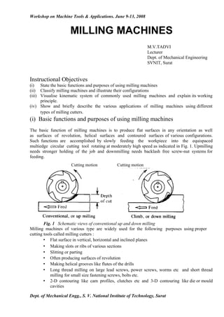
- 1. Workshop on Machine Tools & Applications. June 9-13, 2008 MILLING MACHINES M.V.TADVI Lecturer Dept. of Mechanical Engineering SVNIT, Surat Instructional Objectives (i) State the basic functions and purposes of using milling machines (ii) Classify milling machines and illustrate their configurations (iii) Visualise kinematic system of commonly used milling machines and explain its working principle. (iv) Show and briefly describe the various applications of milling machines using different types of milling cutters. (i) Basic functions and purposes of using milling machines The basic function of milling machines is to produce flat surfaces in any orientation as well as surfaces of revolution, helical surfaces and contoured surfaces of various configurations. Such functions are accomplished by slowly feeding the workpiece into the equispaced multiedge circular cutting tool rotating at moderately high speed as indicated in Fig. 1. Upmilling needs stronger holding of the job and downmilling needs backlash free screw-nut systems for feeding. Cutting motion Cutting motion Fig. 1 Schematic views of conventional up and down milling Milling machines of various type are widely used for the following purposes using proper cutting tools called milling cutters : • Flat surface in vertical, horizontal and inclined planes • Making slots or ribs of various sections • Slitting or parting • Often producing surfaces of revolution • Making helical grooves like flutes of the drills • Long thread milling on large lead screws, power screws, worms etc and short thread milling for small size fastening screws, bolts etc. • 2-D contouring like cam profiles, clutches etc and 3-D contouring like die or mould cavities Dept. of Mechanical Engg., S. V. National Institute of Technology, Surat
- 2. Workshop on Machine Tools & Applications. June 9-13, 2008 • Cutting teeth in piece or batch production of spur gears, straight toothed bevel gears, worm wheels, sprockets, clutches etc. • Producing some salient features like grooves, flutes, gushing and profiles in various cutting tools, e.g., drills, taps, reamers, hobs, gear shaping cutters etc. (ii) Classification of milling machines Milling machines can be broadly classified; (a) According to nature of purposes of use : • general purpose – most versatile commonly used mainly for piece or small lot production • single purpose – e.g., thread milling machines, cam milling machines and slitting machine which are generally used for batch or lot production. • Special purpose – these are used for lot or mass production, e.g., duplicating mills, die sinkers, short thread milling etc. (b) According to configuration and motion of the work-holding table / bed • Knee type : typically shown in Fig. 2. In such small and medium duty machines the table with the job/work travels over the bed (guides) in horizontal (X) and transverse (Y) directions and the bed with the table and job on it moves vertically (Z) up and down. Machine parts : 1. column 2. bed 3. cross slide 4. work table 5. ram 6. ram support 7. arbour support Table feed motions : a. longitudinal feed b. cross feed c. vertical feed Fig. 2 Knee type milling machine • Bed type (Fig. 3) : Usuallyof larger size and capacity; the vertical feed is given to the milling head instead of the knee type bed Dept. of Mechanical Engg., S. V. National Institute of Technology, Surat
- 3. Workshop on Machine Tools & Applications. June 9-13, 2008 Fig. 3 Bed type milling machine • Planer type (Fig. 4) : These heavy duty large machines, called plano-miller, look like planing machine where the single point tools are replaced by one or a number of milling heads; generally used for machining a number of longitudinal flat surfaces simultaneously, viz., lathe beds, table and bed of planning machine etc. • Rotary table type : Such open or closed ended high production milling machines possess one large rotary work-table and one or two vertical spindles as typically shown in Fig. 5; the positions of the job(s) and the milling head are adjusted according to the size and shape of the job. Fig. 4 Planer type milling machine Fig 5. Rotary table type milling machine (c) According to the orientation of the spindle(s). • Plain horizontal knee type (Fig. 6) This non-automatic general purpose milling machine of small to medium size possesses a single horizontal axis milling arbour; the work-table can be linearly fed along three axes (X,Y, Z) only; these milling machines are most widely used for piece or batch production of jobs of relatively simpler configuration and geometry Fig. 6 Plain horizontal knee type milling machine • Horizontal axis (spindle) and swivelling bed type Dept. of Mechanical Engg., S. V. National Institute of Technology, Surat
- 4. Workshop on Machine Tools & Applications. June 9-13, 2008 These are very similar to the plain horizontal arbour knee type machines but possess one additional swivelling motion of the work- table • Vertical spindle type In this machine, typically shown in Fig. 7 the only spindle is vertical and works using end mill type and face milling cutters; the table may or may not have swivelling features • Universal head milling machine These versatile milling machines, typically shown in Fig. 8 not only possess both horizontal milling arbour and the vertical axis spindle, the latter spindle can be further tilted about one (X) or both the horizontal axes (X and Y) enabling machining jobs of complex shape. Fig. 7 Vertical spindle type milling machine Fig 8 Universal head milling (a,b) (d) According to mechanisation / automation and production rate Milling machines are mostly general purpose and used for piece or small lot production. But like other machine tools, some milling machines are also incorporated with certain type and degree of automation or mechanisation to enhance production rate and consistency of product quality. In this respect milling machines can be further classified as follows : Dept. of Mechanical Engg., S. V. National Institute of Technology, Surat
- 5. Workshop on Machine Tools & Applications. June 9-13, 2008 • Hand mill (milling machine) - this is the simplest form of milling machine where even the table feed is also given manually as can be seen in Fig. 9. Fig. 9 Hand mill milling machin Dept. of Mechanical Engg., S. V. National Institute of Technology, Surat
- 6. Workshop on Machine Tools & Applications. June 9-13, 2008 • Planer and rotary table type vertical axis milling machines are not that automated but provide relatively higher production rate • Tracer controlled copy milling machine, typically shown in Fig. 10 are mechanically or hydraulically operated semi-automatic milling machines used for lot production of cams, dies etc by copying the master piece • Milling machines for short thread milling may be considered single purpose and automatic machine being used for mass production of small bolts and screws. Fig.10 Tracer controlled milling machine • Computer Numerical Controlled (CNC) milling machine Replacement of hard or rigid automation by Flexible automation by developing and using CNC has made a great break through since mid seventies in the field of machine tools’ control. The advantageous characteristics of CNC machine tools over conventional ones are : • flexibility in automation • change-over (product) time, effort and cost are much less • less or no jigs and fixtures are needed • complex geometry can be easily machined • high product quality and its consistency • optimum working condition is possible • lesser breakdown and maintenance requirement Fig. 11 typically shows a CNC milling machine. The versatility of CNC milling machine has been further enhanced by developing what is called Machining Centre. Fig. 12 visualises one of such Machining Centres. Dept. of Mechanical Engg., S. V. National Institute of Technology, Surat
- 7. Workshop on Machine Tools & Applications. June 9-13, 2008 Fig. 11 and 12 CNC milling machine and milling centre Dept. of Mechanical Engg., S. V. National Institute of Technology, Surat
- 8. Workshop on Machine Tools & Applications. June 9-13, 2008 (iii) Kinematic system of milling machine The kinematic system comprising of a number of kinematic chains of several mechanisms enables transmission of motions (and power) from the motor to the cutting tool for its rotation at varying speeds and to the work-table for its slow feed motions along X, Y and Z directions. In some milling machines the vertical feed is given to the milling(cutter) head. The more versatile milling machines additionally possess the provisions of rotating the work table and tilting the vertical milling spindle about X and / or Y axes. Fig. 13 typically shows the kinematic diagram of the most common and widely used milling machine having rotation of the single horizontal spindle or arbour and three feed motions of the work- table in X, Y and Z directions. The milling cutter mounted on the horizontal milling arbour, receives its rotary motion at different speeds from the main motor through the speed gear box which with the help of cluster gears splits the single speed into desirably large number(12, 16, 18, 24 etc) of spindle speeds. Power is transmitted to the speed gear box through Vee-belts and a safety clutch as shown in the diagram. For the feed motions of the workpiece (mounted on the work-table) independently, the cutter speed, rotation of the input shaft of the speed gear box is transmitted to the feed gear box through reduction (of speed) by worm and worm wheels as shown. The cluster gears in the feed gear box enables provide a number of feed rates desirably. The feeds of the job can be given both manually by rotating the respective wheels by hand as well as automatically by engaging the respective clutches. The directions of the longitudinal (X), cross (Y) and vertical (Z) feeds are controlled by appropriately shifting the clutches. The system is so designed that the longitudinal feed can be combined with the cross feed or vertical feed but cross feed and vertical feed cannot be obtained simultaneously. This is done for safety purpose. A telescopic shaft with universal joints at its ends is incorporated to transmit feed motion from the fixed position of the feed gear box to the bed (and table) which moves up and down requiring change in length and orientation of the shaft. The diagram also depicts that a separate small motor is provided for quick traverse of the bed and table with the help of an over running clutch. During the slow working feeds the rotation is transmitted from the worm and worm wheel to the inner shaft through three equi-spaced rollers which get jammed into the tapering passage. During quick unworking work-traverse, the shaft is directly rotated by that motor on-line without stopping or slowing down the worm. Longer arbours can also be fitted, if needed, by stretching the over-arm. The base of the milling machine is grouted on the concrete floor or foundation. Dept. of Mechanical Engg., S. V. National Institute of Technology, Surat
- 9. Workshop on Machine Tools & Applications. June 9-13, 2008 Fig. 13 Kinematic diagram of a milling machine (iv) Various applications of milling machines using different types of milling cutters. Milling machines are mostly general purpose and have wide range of applications requiring various types and size of milling cutters. Intermittent cutting nature and usually complex geometry necessitate making the milling Dept. of Mechanical Engg., S. V. National Institute of Technology, Surat
- 10. Workshop on Machine Tools & Applications. June 9-13, 2008 cutters mostly by HSS which is unique for high tensile and transverse rupture strength, fracture toughness and formability almost in al respects i.e. forging, rolling, powdering, welding, heat treatment, machining (in annealed condition) and grinding. Tougher grade cemented carbides are also used without or with coating, where feasible, for high productivity and product quality. Broad classifications of milling cutters Milling cutters are broadly classified as, (a) Profile sharpened cutters – where the geometry of the machined surfaces are not related with the tool shape, viz; i. Slab or plain milling cutter : straight or helical fluted ii. side milling cutters – single side or both sided type iii. slotting cutter iv. slitting or parting tools v. end milling cutters – with straight or taper shank vi. face milling cutters (b) Form relieved cutters – where the job profile becomes the replica of the tool-form, e.g., viz.; i. Form cutters ii. gear (teeth) milling cutters iii. spline shaft cutters iv. tool form cutters v. T-slot cutters vi. Thread milling cutter Various uses of different milling cutters and milling machines Use of profile sharpened cutters The profile sharpened cutters are inherently used for making flat surfaces or surface bounded by a number of flat surfaces only. • Slab or Plain milling cutters : - Plain milling cutters are hollow straight HSS cylinder of 40 to 80 mm outer diameter having 4 to 16 straight or helical equi-spaced flutes or cutting edges and are used in horizontal arbour to machine flat surface as shown in Fig. 14. Fig. 14 Machining flat surface by slab milling. Dept. of Mechanical Engg., S. V. National Institute of Technology, Surat
- 11. Workshop on Machine Tools & Applications. June 9-13, 2008 • Side and slot milling cutters These arbour mounted disc type cutters have a large number of cutting teeth at equal spacing on the periphery. Each tooth has a peripheral cutting edge and another cutting edge on one face in case of single side cutter and two more cutting edges on both the faces leading to double sided cutter. One sided cutters are used to produce one flat surface or steps comprising two flat surfaces at right angle as shown in Fig. 15 Both sided cutters are used for making rectangular slots bounded by three flat surfaces. Slotting is also done by another similar cutter having only one straight peripheral cutting on each tooth. These cutters may be made from a single piece of HSS or its teeth may be of carbide blades brazed on the periphery or clamped type uncoated or coated carbide inserts for high production machining. • Slitting saw or parting tool (Fig. 15) These milling cutters are very similar to the slotting cutters having only one peripheral cutting edge on each tooth. However, the slitting saws are larger in diameter and much thin possess large number of cutting teeth but of small size used only for slitting or parting (a) parallel facing by (b) slotting by side (double sided) two side (single) cutter (c) Parting by slitting saw Fig. 15 Side milling cutters and slitting saw their use • End milling cutters or End mills The shape and the common applications of end milling cutters (profile sharpened type) are shown in Fig.16 The common features and characteristics of such cutters are : mostly made of HSS 4 to 12 straight or helical teeth on the periphery and face diameter ranges from about 1 mm to 40 mm very versatile and widely used in vertical spindle type milling machines Dept. of Mechanical Engg., S. V. National Institute of Technology, Surat
- 12. Workshop on Machine Tools & Applications. June 9-13, 2008 end milling cutters requiring larger diameter are made as a separate cutter body which is fitted in the spindle through a taper shank arbour as shown in the same figure. Dept. of Mechanical Engg., S. V. National Institute of Technology, Surat
- 13. Workshop on Machine Tools & Applications. June 9-13, 2008 • Face milling cutters The shape, geometry and typical use of face milling cutters are shown in fig. 17. The main features are (a) face milling (b) angular milling (c) slotting (d) shell milling Fig. 16 Use of end milling cutters and shell mill • Face milling cutters The shape, geometry and typical use of face milling cutters are shown in Fig. 17 The main features are : • usually large in diameter (80 to 800 mm) and heavy • used only for machining flat surfaces in different orientations • mounted directly in the vertical and / or horizontal spindles • coated or uncoated carbide inserts are clamped at the outer edge of the carbon steel body as shown • generally used for high production machining of large jobs. Dept. of Mechanical Engg., S. V. National Institute of Technology, Surat
- 14. Workshop on Machine Tools & Applications. June 9-13, 2008 Fig 17 Face milling cutter and their working Use of form relieved cutters (milling) The distinguishing characteristics of such cutters, in contrast to profile sharpened cutters, are ; • form of the tool is exactly replica of the job-profile to be made • clearance or flank surfaces of the teeth are of archemedian spiral shaped instead of flat • teeth are sharpened by grinding the rake surface only • used for making 2-D and 3-D contour surfaces The configurations and applications of several form relieved type milling cutters of common use are briefly presented. • Form cutters Such disc type HSS cutters are generally used for making grooves or slots of various profiles as indicated in Fig. 4.3.18. Form cutters may be also end mill type like T-slot cutter as shown in Fig. 4.3.19 Fig. 18 Form cutters and their use Fig 19 cutting Tslots • Gear teeth milling cutters Gear milling cutters are made of HSS and available mostly in disc form like slot milling cutters and also in the form of end mill for producing teeth of large module gears. The form of these tools conform to the shape of the gear tooth-gaps bounded by two involutes as shown in Fig. 20 Such form relieved cutters can Dept. of Mechanical Engg., S. V. National Institute of Technology, Surat
- 15. Workshop on Machine Tools & Applications. June 9-13, 2008 be used for producing teeth of straight and helical toothed external spur gears and worm wheels as well a Straight toothed bevel gears. Fig. 20 Gear milling cutters and their use • Spline shaft cutters These disc type HSS form relieved cutters are used for cutting the slots of external spline shafts having 4 to 8 straight axial teeth. Fig.21 typically shows such application. Fig. 21 Spline shaft cutter • Tool form cutters Form milling type cutters are also used widely for cutting slots or flutes of different cross section e.g. the flutes of twist drills (Fig. 22), milling cutters, reamers etc., and gushing of hobs, taps, short thread milling cutters etc. Dept. of Mechanical Engg., S. V. National Institute of Technology, Surat
- 16. Workshop on Machine Tools & Applications. June 9-13, 2008 Fig. 22 Cutting of drill flutes by form milling cutter • Thread milling cutter Such shank type solid HSS or carbide cutters having thread like annular grooves with equi-spaced gushings are used in automatic single purpose milling machines for cutting the threads in large lot production of screws, bolts etc. Both internal and external threads are cut by the tool as shown in Fig. 23. The milling cutter and its use in long thread milling (e.g. lead screws, power screws, worms etc.) are shown in Fig. 24 Fig. 23 short thread milling Fig. 24 Long thread milling Dept. of Mechanical Engg., S. V. National Institute of Technology, Surat
- 17. Some other applications of milling machines using suitable milling cutters • Straddle milling For faster and accurate machining two parallel vertical surfaces at a definite distance, two separate side milling cutters are mounted at appropriate distance on the horizontal milling arbour as shown in Fig. 25. Fig. 25 Straddle milling • Gang milling In gang milling, being employed, where feasible, for quick production of complex contours comprising a number of parallel flat or curved surfaces a proper combination of several cutters are mounted tightly on the same horizontal milling arbour as indicated in Fig. 4.3.26 Fig. 26 Gang milling • Ball-nose end mill Small HSS end mill with ball like hemispherical end , as shown in Fig. 28, is often used in CNC milling machines for machining free form 3- D or 2-D contoured surfaces. Fig. 27 Ball nose end mills Ball nose end mills may be made of HSS, solid carbide or steel body with
- 18. coated or uncoated carbide inserts clamped at its end as can be seen in the figure. Beside the aforesaid applications, the versatile milling processes using several other types of milling cutters are employed for many other machining work like cam milling, keyway cutting, making hob cutter and so on. For enhancing capability range of milling work a number of attachments are fitted in the milling machines. Such milling attachments include • universal milling and spiral milling attachment • indexing head – simple, compound and differential type • universal milling and spiral milling attachment • copying attachment (mechanical and hydraulic (tracer control)) • slotting attachment • Gear milling Milling is a form-cutting process limited to making single gears for prototype or very small batches of gears as it is a very slow and uneconomical method of production. A involute form-milling cutter, which has the the profile of the space between the gears, is used to remove the material between the teeth from the gear blank on a horizontal milling machine. The depth of cut into the gear blank depends on the cutter strength, set-up rigidity and machineability of the gear blank material.