

Recomendados
Más contenido relacionado
La actualidad más candente
La actualidad más candente (20)
Destacado
Similar a Roland V-8
Similar a Roland V-8 (20)
Más de AV ProfShop
Más de AV ProfShop (20)
Último
Último (20)
Roland V-8
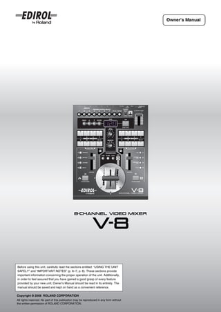
- 1. Owner’s Manual Before using this unit, carefully read the sections entitled: “USING THE UNIT SAFELY” and “IMPORTANT NOTES” (p. 6–7; p. 8). These sections provide important information concerning the proper operation of the unit. Additionally, in order to feel assured that you have gained a good grasp of every feature provided by your new unit, Owner’s Manual should be read in its entirety. The manual should be saved and kept on hand as a convenient reference. Copyright © 2008 ROLAND CORPORATION All rights reserved. No part of this publication may be reproduced in any form without the written permission of ROLAND CORPORATION.
- 2. Confirm the Contents of the Package The V-8 includes the following items. Please take a moment to confirm that all of these items have been included with the V-8. If you find that any item is missing, contact the nearest authorized EDIROL/Roland distributor in your country. V-8 RCA-BNC adaptor plugs (four) Screws for attaching the video fader (four spare screws) Owner’s manual (this document) AC adaptor/Power cord * The shape of the power cord’s plug varies depending on the country. For the U.K. IMPORTANT: THE WIRES IN THIS MAINS LEAD ARE COLOURED IN ACCORDANCE WITH THE FOLLOWING CODE. BLUE: NEUTRAL BROWN: LIVE As the colours of the wires in the mains lead of this apparatus may not correspond with the coloured markings identifying the terminals in your plug, proceed as follows: The wire which is coloured BLUE must be connected to the terminal which is marked with the letter N or coloured BLACK. The wire which is coloured BROWN must be connected to the terminal which is marked with the letter L or coloured RED. Under no circumstances must either of the above wires be connected to the earth terminal of a three pin plug. 2
- 3. Main Features ● Eight channels of video input The V-8 provides video input connectors for eight video (composite) channels and four S-video channels. Of the input channels 1–8, S-video input is available only for channels 5–8. * If S-video and video (composite) are both input to a channel 5–7, the input from the S-video connector will take priority and will be selected automatically. Likewise, if S-video and RGB signals from a computer are both input to channel 8, the S-video will take priority. ● Computer input jacks with built-in scan converters A built-in scan converter supports RGB signals (VGA to UXGA) from a computer. The incoming RGB signal is converted to a video signal. By key-compositing a computer screen with a video image, you can use this as a titler. * There are two computer input connectors. A switch on the operating panel allows one of the two to be selected. ● Two independent frame synchronizers Even if an unstable video signal is input, the internal frame synchronizer can correct the synchronization signal. This allows you to use a variety of video without worrying about noise caused by unstable synchronization signals. ● Monitor out connectors for eight channels An independent monitor out connector is provided for each video input channel 1–8. * If both S-video and video (composite) signals are being input to channels 5–7, or if both an S-video signal and a computer output signal are being input to channel 8, the input from the S-video connector will take priority, and will be sent from monitor out. The input signal from the computer will also be sent from monitor out as a video signal. ● High-quality digital effects Digitally processed effects are built in. You can apply a variety of high-quality effects including Picture In Picture, Mirror, Multi, Feedback, and Afterimage. In addition to the familiar Mix and Wipe transitions, new transitions such as FAM (Full Additive Mix), NAM (Non-Additive Mix), Slide, and Stretch are also provided. ● Simple and customizable operation Switching between video sources and mixing them is easy. The T-bar type video fader can be attached in either a horizontal or vertical orientation according to your preference. Sliders are used for effect controllers, allowing you to operate the V-8 like a DJ mixer. ● Synchronize with music By pressing the TAP button in time with the beat of the music, you can switch images or control effects in synchronization with the tempo (BPM). ● Control via MIDI MIDI connectors (IN, OUT/THRU) are provided, allowing you to switch images or control effects by controlling the V-8 from an external MIDI device. You can also control an external device from the V-8. In addition, the V-8 can be used in conjunction with V-LINK compatible audio/video equipment to easily create video output that is linked with the expressive elements of a performance. 3
- 4. Table of Contents Introduction Confirm the Contents of the Package ......................................................................................................................................2 Main Features .............................................................................................................................................................................3 USING THE UNIT SAFELY .........................................................................................................................................................6 IMPORTANT NOTES ..................................................................................................................................................................8 Video Signal Flow ......................................................................................................................................................................9 Panel Descriptions...................................................................................................................................................................10 Connecting Peripheral Devices 14 Basic Connections...................................................................................................................................................................14 Connecting the AC Adaptor .................................................................................................................................................15 Examples of Using the V-8 ......................................................................................................................................................16 Basic Operation 20 Turning the Power On/Off .......................................................................................................................................................20 Checking the Input and Output...............................................................................................................................................21 Outputting Images ...............................................................................................................................................................21 Outputting a Preview Image ................................................................................................................................................22 Menu Operations......................................................................................................................................................................23 Preparations for Viewing the Menu......................................................................................................................................23 Operating the Menu .............................................................................................................................................................24 About the Current Settings Display .......................................................................................................................................26 Changing the Contents of the Settings Display ...................................................................................................................27 Storing the Operating Panel Settings ([MEMORY] Knob) ....................................................................................................28 Settings Stored at the [MEMORY] Knob..............................................................................................................................28 Recalling a Memory .............................................................................................................................................................29 Copying the Contents of a Memory .....................................................................................................................................29 Exchanging the Contents of Memories................................................................................................................................30 Fading Out the Output Image..................................................................................................................................................31 Fading Out the Bus A / Bus B Image...................................................................................................................................31 Fading Out the Final Output ................................................................................................................................................32 Returning the Menu Settings to the Factory-Set State (Factory Reset)..............................................................................33 Returning All Settings to the Factory-Set State ...................................................................................................................33 Returning the Settings of a Specific Sub-Menu to the Factory-Set State ............................................................................34 Switching Between Images 35 Switching Between Two Images.............................................................................................................................................35 Changing the Transition Assigned to Each TRANSITION Button .......................................................................................36 Combining Multiple Transition Effects (User Transition)......................................................................................................38 Using the [TRANSFORMER] Buttons to Switch Images ......................................................................................................40 Changing the Assignment of the [TRANSFORMER] Buttons..............................................................................................41 Using Effects 42 About Effects............................................................................................................................................................................42 Combining Two Images...........................................................................................................................................................43 Using Picture In Picture (P in P) to Combine Images ..........................................................................................................43 Using Chroma-Key to Combine Images ..............................................................................................................................45 Using Luminance-Key to Combine Images .........................................................................................................................46 Changing the Color of the Image............................................................................................................................................48 Inverting the Image to Form a Negative ..............................................................................................................................48 Adding Color According to the Brightness or Darkness of the Image (Colorize) .................................................................49 Repeatedly Layering an Image onto Itself (Feedback) .........................................................................................................50 Using Multi-Screen...................................................................................................................................................................51 Inverting the Image (Flip) ........................................................................................................................................................52 Assigning Different Effects to the EFFECTS Buttons ..........................................................................................................53 4
- 5. Table of Contents (continued) Editing the Input/Output Settings 54 Introduction Adjusting the Input Image .......................................................................................................................................................54 Adjusting the PC Input Image ..............................................................................................................................................54 Adjusting the Input Image for Bus A and B..........................................................................................................................56 Adjusting the Output Image ....................................................................................................................................................57 Outputting Color Bars .............................................................................................................................................................58 Connections Switching Between NTSC and PAL ........................................................................................................................................59 Switching Images in Synchronization with Music (BPM Sync) 60 Switching Images at a Specified BPM....................................................................................................................................60 Switching Images at the Tempo Specified by the [TAP] Button..........................................................................................61 Basic operation Changing the Settings of the [BPM SYNC] Button ...............................................................................................................62 Using the V-8 with Other Equipment 63 Using MIDI to Control the V-8 from an External Device .......................................................................................................63 About MIDI...........................................................................................................................................................................63 Switching images Buttons and Knobs that Transmit or Receive MIDI Messages ............................................................................................64 MIDI Message Transmission Settings .................................................................................................................................66 MIDI Message Reception Settings ......................................................................................................................................68 Saving V-8 Settings on an External MIDI Device (Bulk Dump) ............................................................................................69 Transmitting Menu Setting Data to an External MIDI Device ..............................................................................................69 Restoring Data Saved on an External MIDI Device Back into the V-8 ................................................................................70 Sending the V-8’s Settings to Another V-8 ..........................................................................................................................71 Controlling via V-LINK .............................................................................................................................................................72 Effects What is V-LINK? ..................................................................................................................................................................72 Controlling the RSS M-400 from the V-8 (V-LINK Master) ..................................................................................................72 Controlling the V-8 from an External V-LINK Compatible Device (V-LINK Slave)...............................................................74 Using the V-8 in Conjunction with the PR Series (PR Control mode).................................................................................75 Adjusting the Video Fader 76 Input/output settings Installing the Video Fader in the Most Convenient Orientation...........................................................................................76 Calibrating the Video Fader ....................................................................................................................................................77 Specifying the Video Fader Operating Curve........................................................................................................................78 Appendices 79 BPM sync Troubleshooting.......................................................................................................................................................................79 Menu List ..................................................................................................................................................................................81 MIDI Implementation ................................................................................................................................................................90 MIDI Implementation Chart......................................................................................................................................................98 External devices Transition Effect List ...............................................................................................................................................................99 Effect List................................................................................................................................................................................105 Effects that Can Be Controlled by the [CONTROL] Fader.................................................................................................106 Effects that Cannot Be Used Simultaneously ....................................................................................................................107 Block Diagram ........................................................................................................................................................................108 Main Specifications................................................................................................................................................................109 Index........................................................................................................................................................................................110 Video fader Information .............................................................................................................................................................................113 Appendices 5
- 6. USING THE UNIT SAFELY Used for instructions intended to alert The symbol alerts the user to important instructions the user to the risk of death or severe or warnings.The specific meaning of the symbol is injury should the unit be used determined by the design contained within the triangle. improperly. In the case of the symbol at left, it is used for general cautions, warnings, or alerts to danger. Used for instructions intended to alert The symbol alerts the user to items that must never the user to the risk of injury or material be carried out (are forbidden). The specific thing that damage should the unit be used must not be done is indicated by the design contained improperly. within the circle. In the case of the symbol at left, it * Material damage refers to damage or means that the unit must never be disassembled. other adverse effects caused with The ● symbol alerts the user to things that must be respect to the home and all its carried out. The specific thing that must be done is furnishings, as well to domestic indicated by the design contained within the circle. In animals or pets. the case of the symbol at left, it means that the power- cord plug must be unplugged from the outlet. 002d 008e ● Do not open or perform any internal modifications on the ● Use only the attached power-supply cord. Also, the unit or its AC adaptor. (The only exception would be supplied power cord must not be used with any other where this manual provides specific instructions; see device. p. 76.) .......................................................................................................... 009 ● Do not excessively twist or bend the power cord, nor .......................................................................................................... place heavy objects on it. Doing so can damage the 003 cord, producing severed elements and short circuits. ● Do not attempt to repair the unit, or replace parts within Damaged cords are fire and shock hazards! it (except when this manual provides specific instructions directing you to do so). Refer all servicing to .......................................................................................................... 011 your retailer, the nearest EDIROL/Roland Service ● Do not allow any objects (e.g., flammable material, Center, or an authorized EDIROL/Roland distributor, as coins, pins); or liquids of any kind (water, soft drinks, listed on the “Information” page. etc.) to penetrate the unit. .......................................................................................................... 004 ● Never use or store the unit in places that are: • Subject to temperature extremes (e.g., direct sunlight .......................................................................................................... in an enclosed vehicle, near a heating duct, on top of 012b heat-generating equipment); or are ● Immediately turn the power off, remove the AC adaptor from the outlet, and request servicing by your retailer, • Damp (e.g., baths, washrooms, on wet floors); or are the nearest EDIROL/Roland Service Center, or an • Humid; or are authorized EDIROL/Roland distributor, as listed on the • Exposed to rain; or are “Information” page when: • Dusty; or are • The AC adaptor, the power-supply cord, or the plug • Subject to high levels of vibration. has been damaged; or .......................................................................................................... • If smoke or unusual odor occurs 007 • Objects have fallen into, or liquid has been spilled ● Make sure you always have the unit placed so it is level onto the unit; or and sure to remain stable. Never place it on stands that could wobble, or on inclined surfaces. • The unit has been exposed to rain (or otherwise has .......................................................................................................... become wet); or 008c • The unit does not appear to operate normally or ● Be sure to use only the AC adaptor supplied with the exhibits a marked change in performance. unit. Also, make sure the line voltage at the installation .......................................................................................................... matches the input voltage specified on the AC adaptor’s 013 body. Other AC adaptors may use a different polarity, or ● In households with small children, an adult should be designed for a different voltage, so their use could provide supervision until the child is capable of following result in damage, malfunction, or electric shock. all the rules essential for the safe operation of the unit. .......................................................................................................... .......................................................................................................... 6
- 7. USING THE UNIT SAFELY (continued) 014 101b ● Protect the unit from strong impact. ● The unit and the AC adaptor should be located so their (Do not drop it!) location or position does not interfere with their proper ventilation. .......................................................................................................... Introduction .......................................................................................................... 015 102c ● Do not force the unit’s power-supply cord to share an ● Always grasp only the plug on the AC adaptor cord outlet with an unreasonable number of other devices. Be when plugging into, or unplugging from, an outlet or this especially careful when using extension cords—the total unit. power used by all devices you have connected to the .......................................................................................................... extension cord’s outlet must never exceed the power 103b rating (watts/amperes) for the extension cord. Excessive ● At regular intervals, you should unplug the AC adaptor Connections loads can cause the insulation on the cord to heat up and clean it by using a dry cloth to wipe all dust and and eventually melt through. other accumulations away from its prongs. Also, .......................................................................................................... disconnect the power plug from the power outlet 016 whenever the unit is to remain unused for an extended ● Before using the unit in a foreign country, consult with period of time. Any accumulation of dust between the your retailer, the nearest EDIROL/Roland Service power plug and the power outlet can result in poor Center, or an authorized EDIROL/Roland distributor, as insulation and lead to fire. Basic operation listed on the “Information” page. .......................................................................................................... .......................................................................................................... 104 022b ● Try to prevent cords and cables from becoming ● Always turn the unit off and unplug the AC adaptor entangled. Also, all cords and cables should be placed before attempting installation of the video fader (p. 76). so they are out of the reach of children. .......................................................................................................... .......................................................................................................... 106 Switching images ● Never climb on top of, nor place heavy objects on the unit. .......................................................................................................... 107c ● Never handle the AC adaptor or its plugs with wet hands when plugging into, or unplugging from, an outlet or this unit. .......................................................................................................... Effects 108b ● Before moving the unit, disconnect the AC adaptor and all cords coming from external devices. .......................................................................................................... 109b ● Before cleaning the unit, turn off the power and unplug Input/output the AC adaptor from the outlet. settings .......................................................................................................... 110b ● Whenever you suspect the possibility of lightning in your area, disconnect the AC adaptor from the outlet. .......................................................................................................... 115a BPM sync ● For installation of the video fader, remove only the specified screws (p. 76). .......................................................................................................... 118c ● Keep any screws for the attaching the video fader and ground terminal you may remove and the included RCA- External devices BNC adaptor plugs and screws for attaching the video fader in a safe place out of children’s reach, so there is no chance of them being swallowed accidentally. .......................................................................................................... Video fader Appendices 7
- 8. IMPORTANT NOTES Power Supply Additional Precautions 301 *** ● Do not connect this unit to same electrical outlet that is being ● This unit allows you to switch images or turn video effects on/off used by an electrical appliance that is controlled by an inverter at high speed. For some people, viewing such images can cause (such as a refrigerator, washing machine, microwave oven, or air headache, nausea, or other discomfort. Do not use this unit to conditioner), or that contains a motor. Depending on the way in create video that might cause these types of health problems. which the electrical appliance is used, power supply noise may Roland Corporation will accept no responsibility for any such cause this unit to malfunction or may produce visible noise. If it is health problems that may occur in yourself or in viewers. not practical to use a separate electrical outlet, connect a power 551 ● Please be aware that the contents stored at the [MEMORY] knob supply noise filter between this unit and the electrical outlet. 302 (p. 28) can be irretrievably lost as a result of a malfunction, or the ● The AC adaptor will begin to generate heat after long hours of improper operation of the unit. To protect yourself against the risk consecutive use. This is normal, and is not a cause for concern. of loosing important data, we recommend that you periodically 307 save a backup copy of important data you have stored in the ● Before connecting this unit to other devices, turn off the power to unit’s memory in another MIDI device (e.g., a sequencer). all units. This will help prevent malfunctions and/or damage to 552 video monitors or other devices. ● Unfortunately, it may be impossible to restore the contents of data that was stored in another MIDI device (e.g., a sequencer) once it has been lost. Roland Corporation assumes no liability Placement concerning such loss of data. 553 352a ● Use a reasonable amount of care when using the unit’s buttons, ● This unit may interfere with radio and television reception. Do not sliders, or other controls; and when using its jacks and use this unit in the vicinity of such receivers. connectors. Rough handling can lead to malfunctions. 352b 556 ● Noise may be produced if wireless communications devices, such ● When connecting / disconnecting all cables, grasp the connector as cell phones, are operated in the vicinity of this unit. Such noise itself—never pull on the cable. This way you will avoid causing could occur when receiving or initiating a call, or while shorts, or damage to the cable’s internal elements. conversing. Should you experience such problems, you should 559c relocate such wireless devices so they are at a greater distance ● When you need to transport the unit, package it in the box from this unit, or switch them off. (including padding) that it came in, if possible. Otherwise, you will 355b need to use equivalent packaging materials. ● When moved from one location to another where the temperature and/or humidity is very different, water droplets (condensation) may form inside the unit. Damage or malfunction may result if you attempt to use the unit in this condition. Therefore, before using Copyright the unit, you must allow it to stand for several hours, until the 851 ● Recording, duplication, distribution, sale, lease, performance, or condensation has completely evaporated. 360 broadcast of copyrighted material (musical works, visual works, ● Depending on the material and temperature of the surface on broadcasts, live performances, etc.) belonging to a third party in which you place the unit, its rubber feet may discolor or mar the part or in whole without the permission of the copyright owner is surface. forbidden by law. You can place a piece of felt or cloth under the rubber feet to 852a ● This product can be used to record or duplicate visual material prevent this from happening. If you do so, please make sure that without being limited by certain technological copy-protection the unit will not slip or move accidentally. measures. This is due to the fact that this product is intended to be used for the purpose of producing original video material, and is therefore designed so that material that does not infringe Maintenance copyrights belonging to others (for example, your own original 401a works) can be recorded or duplicated freely. ● For everyday cleaning wipe the unit with a soft, dry cloth or one 853 that has been slightly dampened with water. To remove stubborn ● Do not use this unit for purposes that could infringe on a copyright dirt, use a cloth impregnated with a mild, non-abrasive detergent. held by a third party. We assume no responsibility whatsoever Afterwards, be sure to wipe the unit thoroughly with a soft, dry with regard to any infringements of third-party copyrights arising cloth. through your use of this unit. 402 ● Never use benzine, thinners, alcohol or solvents of any kind, to avoid the possibility of discoloration and/or deformation. Repairs and Data 452 ● Please be aware that all data contained in the unit’s memory may be lost when the unit is sent for repairs. Important data should always be backed up in another MIDI device (e.g., a sequencer), or written down on paper (when possible). During repairs, due care is taken to avoid the loss of data. However, in certain cases (such as when circuitry related to memory itself is out of order), we regret that it may not be possible to restore the data, and Roland assumes no liability concerning such loss of data. * Microsoft and Windows are registered trademarks of Microsoft Corporation. 207 * Apple and Macintosh are registered trademarks of Apple Inc. 8
- 9. Video Signal Flow You can use the input selector to choose any two of the video signals coming into the eight input jacks. These two video Introduction signals are sent to bus A and bus B of the video mixer section. The video signals sent to bus A and bus B are mixed in the video mixer section. The mixed signal then passes through the output fader and is sent from the output jack. ☞ For details on the structure of the mixer, refer to “Block Diagram” (p. 108). fig.signal-flow-e.eps Connections Video device Computer Basic operation INPUT1 INPUT2 INPUT3 INPUT4 INPUT5 INPUT6 INPUT7 INPUT8 PC1 PC2 PC input selector Scan converter Switching images Effects Input selector Bus A Bus B Effects Effects Fader Fader Input/output settings Video mixer Output fader BPM sync Preview selector Inside of the V-8 OUTPUT PREVIEW OUT External devices Final output Preview output * The preview output will also show the settings menu of the V-8 overlaid with the image (p. 23). * INPUTs 5–7 provide composite connectors and S-video connectors. If an image is being input to both connectors of the Video fader same channel, the input from the S-video connector will take priority. * INPUT 8 provides both an S-video connector and a PC connector. If an image is being input to both of these, the input from the S-video connector will take priority. Appendices 9
- 10. Panel Descriptions Operating Panel fig.top-panel1-e.eps Menu Operation Buttons [BPM/CONTROL] Knob These are used when working with the menu. ● Use this to edit the BPM value. ☞ “Operating the Menu” (p. 24) ● If you’ve used the TRANSITION buttons ( ) to select “003: ● [MENU] Button Fam✽” or “005: Nam✽” as the transition effect, this will adjust This button overlays the menu onto the television monitor the way in which the transition occurs. connected to the PREVIEW OUT connector (p. 13). ☞ “About the FAM and NAM Transition Effects” (p. 37) If you’ve moved to a lower-level menu, this button will return you to the preceding menu (the next higher level). [MEMORY] Knob If the menu is displayed, the [MENU] button will light. This knob stores up to seven settings (memory numbers 2–8) for the operating panel (i.e., the buttons and faders). The factory ● [ ][ ] Buttons preset settings are assigned to memory number 1. These buttons move the cursor that is displayed in the menu. The stored settings will be called up when you turn the Alternatively, they edit a value in the menu. [MEMORY] knob to the desired memory number. ● [ENTER] Button ☞ “Storing the Operating Panel Settings ([MEMORY] Knob)” (p. 28) This button confirms the menu item you’ve selected, and takes you to the next menu (a lower level). Bus A INPUT SELECT Buttons Use these buttons to select the image that will be input to bus A BPM Display of the video mixer. fig.inputsel-indicator-e.eps ● This shows the current BPM (Beats Per Minute). The indicator of the selected INPUT SELECT Indicator ☞ “Switching Images at a Specified BPM” (p. 60) button will light. ● If you’ve chosen “003: Fam✽” or “005: Nam✽” as the transition ☞ “Switching Between Two Images” (p. 35) effect selected by a TRANSITION button, this will blink to * For channels 5–8, input from the S-video connector will take priority. indicate the FAM/NAM cross point level. * Use the [PC INPUT SELECT] button to choose the input from the PC1/ PC2 connectors. ☞ “Changing the cross point of the FAM/NAM” (p. 37) [TAP] Button You can specify the BPM by pressing the [TAP] button at the desired interval. ☞ “Switching Images at the Tempo Specified by the [TAP] Button” (p. 61) 10
- 11. Panel Descriptions (continued) Bus A EFFECTS Buttons TRANSITION Buttons These buttons turn effects on/off for the bus A image of the video Here you can select the way in which you will transition between mixer. If an effect is on, the button will be lit or blinking. the bus A and bus B images. The button you’ve selected will light. You can use up to four effects simultaneously. The settings listed below are for memory number 1 of the ☞ “Using Effects” (p. 42) [MEMORY] knob. By selecting memory numbers 2–8 you can Introduction * The EFFECTS button will blink if you’ve selected an effect that can be assign different transition effects to each TRANSITION button. controlled by the [CONTROL] fader ( ). For details, refer to “Effects that can be controlled by the [CONTROL] [1 MIX] button Dissolve (001: Mix01) faders” (p. 42). [2 WIPE] button Wipe (008: Wipe03) * Depending on the type of effect, there are some combinations that [3 EFX] button Soft edge wipe (192: SWipe88) cannot be used simultaneously. For details, refer to “Effects that Cannot Be Used Simultaneously” (p. 107). ☞ “Switching Between Two Images” (p. 35) Connections The settings listed below are the settings for memory number 1 of the [MEMORY] knob. By selecting memory numbers 2–8 you [BPM SYNC] Button can assign other effects to the EFFECTS buttons. This lets you automatically switch between images or turn effects on/off in synchronization with the BPM (BMP Sync). [1 (FEEDBACK)] button Feedback (022: FEEDBACK✽) ☞ “Switching Images in Synchronization with Music (BPM Sync)” (p. 60) Negative (033: NEGATIVE✽) Basic operation [2 (NEGATIVE)] button [3 (COLORIZE)] button Colorize (042: COLORIZE✽) PREVIEW OUT SELECT Buttons [4 (MULTI)] button Multi (126: MULTI-HV✽) These buttons select the preview image that will be output from ☞ “Assigning Different Effects to the EFFECTS Buttons” (p. 53) the PREVIEW OUT connector (p. 13). ● [1]–[PC/8] Buttons Bus A [CONTROL] Fader Switching images The image being input to the INPUT 1–8/PC1/PC2 connector will ● You can use this fader to control the settings of an effect be sent from the preview output. The channel number or menu assigned to the blinking EFFECTS button. (p. 23) will be shown overlaid on the preview output. ☞ “Effects that can be controlled by the [CONTROL] faders” (p. 42) * The input from the S-video connector will take priority for channels 5–8. ● If the [FADE] button ( ) is blinking, this will fade in/out the * Use the [PC INPUT SELECT] switch to choose between the PC1/PC2 bus A image. connector inputs. The fade color is fixed at black. * The menu will appear if you press the [MENU] button. ☞ “Fading Out the Bus A / Bus B Image” (p. 31) ● [OUTPUT] Button Effects The final output image will be sent from the preview output. Bus A [FADE] Button Information about the settings (p. 26) or the menu (p. 23) will be This button lets you use the bus A [CONTROL] fader to fade the shown overlaid on the preview output. bus A image. * The menu will appear if you press the [MENU] button. While the [FADE] button is blinking, operating the [CONTROL] Input/output [PC INPUT SELECT] Switch settings fader will fade in/out the bus A image. This switches between the PC1 input and PC2 input. [FADE] button Fade function Blinking On [WHITE/BLACK] Switch Lit On This selects either “white” or “black” as the fade color applied Unlit Off when you operate the [OUTPUT FADE] fader. BPM sync ☞ “Fading Out the Bus A / Bus B Image” (p. 31) WHITE Fade to white BLACK Fade to black Bus A [TRANSFORMER] Button This button switches between the bus A and bus B images [OUTPUT FADE] Fader without using the video fader. External devices Lowering the [OUTPUT FADE] fader will fade out the image (final ☞ “Using the [TRANSFORMER] Buttons to Switch Images” (p. 40) output) being sent from the OUTPUT connector. Video Fader Raising the [OUTPUT FADE] fader will fade in the image. ☞ “Fading Out the Final Output” (p. 32) This is a T-bar type video fader. It switches between the bus A and bus B images. ● OUTPUT FADE indicator ☞ “Switching Between Two Images” (p. 35) The indicator located above the [OUTPUT FADE] fader indicates The video fader can be installed in the V-8 in either a vertical or the fade status. Video fader a horizontal orientation, and you are free to change this to suit Blinking Now fading in/out your preference. Lit Normal output ☞ “Installing the Video Fader in the Most Convenient Orientation” (p. 76) Appendices 11
- 12. Panel Descriptions (continued) Operating Panel (continued) fig.top-panel2-e.eps Bus B INPUT SELECT Buttons Bus B [CONTROL] Fader Use these buttons to select the image that will be input to bus B ● You can use this fader to control the settings of an effect of the video mixer. assigned to the blinking EFFECTS button. fig.inputsel-indicator-e.eps The indicator of the selected INPUT SELECT Indicator ☞ “Effects that can be controlled by the [CONTROL] faders” (p. 42) button will light. ● If the [FADE] button ( ) is blinking, this will fade in/out the ☞ “Switching Between Two Images” (p. 35) bus B image. * For channels 5–8, input from the S-video connector will take priority. The fade color is fixed at black. * Use the [PC INPUT SELECT] button to choose the input from the PC1/ ☞ “Fading Out the Bus A / Bus B Image” (p. 31) PC2 connectors. Bus B [FADE] Button Bus B EFFECTS Buttons This button lets you use the bus B [CONTROL] fader to fade the These buttons turn effects on/off for the bus B image of the video bus B image. mixer. If an effect is on, the button will be lit or blinking. While the [FADE] button is blinking, operating the [CONTROL] You can use up to four effects simultaneously. fader will fade in/out the bus B image. ☞ “Using Effects” (p. 42) * The EFFECTS button will blink if you’ve selected an effect that can be [FADE] button Fade function controlled by the [CONTROL] fader ( ). Blinking On For details, refer to “Effects that can be controlled by the [CONTROL] faders” (p. 42). Lit On * Depending on the type of effect, there are some combinations that Unlit Off cannot be used simultaneously. For details, refer to “Effects that Cannot ☞ “Fading Out the Bus A / Bus B Image” (p. 31) Be Used Simultaneously” (p. 107). The settings listed below are the settings for memory number 1 of the [MEMORY] knob. By selecting memory numbers 2–8 you Bus B [TRANSFORMER] Button can assign other effects to the EFFECTS buttons. This button switches between the bus A and bus B images without using the video fader. [1 (FLIP)] button Flip (102: FLIP✽) ☞ “Using the [TRANSFORMER] Buttons to Switch Images” (p. 40) [2 (CHROMA KEY)] button Chroma key (098: CHROMAKEY✽) [3 (LUMINANCE KEY)] button Luminance key (096:B-LUMIKEY✽) [4 (P in P)] button Picture in picture (150: PinP✽) ☞ “Assigning Different Effects to the EFFECTS Buttons” (p. 53) 12
- 13. Panel Descriptions (continued) Rear Panel fig.rear-panel-e.eps Introduction Connections OUTPUT Connectors PREVIEW OUT Connector Basic operation ● Composite output connectors This is a BNC connector that outputs the composite signal for the These are BNC connectors that output the final output image as image selected by the PREVIEW OUT SELECT buttons (p. 11). a composite video signal. If you are previewing an input image from the INPUT 1–8/PC1/ * If the connection cable you’re using has an RCA phono type plug, use PC2 connectors, the channel number or menu (p. 23) will be the included (or commercially available) RCA-BNC adaptors. overlaid on the image. ● S-video output connector If you are previewing the final output image, the menu (p. 23) or Switching images This outputs the final output image as an S-video signal. information about the settings (p. 26) will be overlaid on the image. * If the connection cable you’re using has an RCA phono type plug, use the included (or commercially available) RCA-BNC adaptors. INPUT Connectors (channels 1–8) * The menu is shown when you press the [MENU] button (p. 10). * For channels 5–8, input from the S-video connector will take priority. ● Composite input connectors (channels 1–7) Ground Terminal These are BNC connectors that input a composite video signal. Use this to connect an external earth or ground. Here you can connect video equipment that has composite video ☞ “About the ground terminal” (p. 15) Effects output connectors. * If the connection cable you’re using has an RCA phono type plug, use Cord Hook the included (or commercially available) RCA-BNC adaptors. Fasten the cord of the included AC adaptor to this hook so that ● S-video input connectors (channels 5–8) the cord will not be disconnected accidentally. These connectors can accept S-video signals. ☞ “Connecting the AC Adaptor” (p. 15) Here you can connect video equipment that has an S-video Input/output settings output connector. AC Adaptor Connector Connect the included AC adaptor here. ● PC1/PC2 input connectors (channel 8) These are D-sub 15-pin connectors for inputting RGB signals. ☞ “Connecting the AC Adaptor” (p. 15) Use the [PC INPUT SELECT] switch (p. 11) to choose between the PC1 input or PC2 input. [POWER] Switch This turns the power on/off. ☞ “Adjusting the PC Input Image” (p. 54) BPM sync ☞ “Turning the Power On/Off” (p. 20) MONITOR OUT Connectors (channels 1–7) MIDI OUT/THRU Connector These are BNC connectors that output the composite video You can switch the function of this connector between MIDI OUT signal from the images being input to the composite input and MIDI THRU. connectors or S-video input connectors. ☞ “MIDI OUT/THRU connector setting” (p. 66) External devices You can connect these to television monitors that have composite video inputs, and use them to view the input image for ● MIDI OUT each channel. This connector will transmit MIDI messages to an external device. * The input from the S-video connector will take priority for channels 5–7. ● MIDI THRU * If the connection cable you’re using has an RCA phono type plug, use This connector will retransmit (without change) any MIDI the included (or commercially available) RCA-BNC adaptors. messages arriving at the MIDI IN connector. MONITOR OUT PC/8 Connector (channel 8) MIDI IN Connector Video fader This is a BNC connector that outputs a composite video signal of This connector receives MIDI messages from an external MIDI the image that is being input to the channel 8 S-video connector device. or to the PC1/PC2 input connector. Here you can connect a television monitor that has a composite Security Slot ( ) video input connector, and use it to view the input image. You can attach a commercially available security lock here. For * The input from the S-video connector will take priority for channel 8. details, refer to the following website: * If the connection cable you’re using has an RCA phono type plug, use Appendices the included (or commercially available) RCA-BNC adaptors. http://www.kensington.com/ 13
- 14. Connecting Peripheral Devices Basic Connections * To prevent malfunction and/or damage to video monitors or other devices, always turn off the power on all devices before making any connections. * Be sure to use cables and adapter plugs with the proper connectors matching those of the other devices you are using. DVD player, Video tape recorder, DV camera Computer Video device VGA output S-video output Composite output connector connector connector *1 VGA cable S-video cable Composite cable *1 Composite connectors can be one of two types: RCA phono type and BNC type. Before making connections, be sure to check the type of plug on your connection RCA-BNC cable and the shape of the composite adaptor plugs connector. If you want to connect an RCA phono type cable to a BNC connector, you’ll need to V-8 Rear panel use the included (or commercially available) RCA-BNC adaptor plugs. Ground terminal RCA-BNC RCA-BNC RCA-BNC RCA-BNC adaptor plugs adaptor plugs adaptor adaptor plugs plugs Composite cable S-video Composite cable Composite cable Composite cable cable Composite input S-video Composite input Composite Composite connector *1 input connector *1 input input connector connector *1 connector *1 Final Monitor the Monitor the Preview monitor output device Projector or TV monitor 8/PC1/PC inputs 1–7 inputs 14
- 15. Connecting Peripheral Devices (continued) ● About the composite connectors and MONITOR OUT connectors The V-8’s composite inputs and outputs use BNC connectors. If your connection cables have RCA phono plugs, you’ll need to use the included (or commercially available) RCA-BNC adaptor plugs. ● About cable routing Using an S-video cable will provide a higher-quality image. However, if the cable routing is very long, noise may Introduction appear in the image. If this occurs, use a composite cable. ● About the inputs The S-video connector input will take priority for input channels 5–8. ● About the final output Connections The same image is sent from all of the OUTPUT connectors (composite connectors and S-video connector). ● About the ground terminal Depending on the circumstances of a particular setup, you may experience a discomforting sensation, or perceive that the surface feels gritty to the touch when you touch this device. This is due to an infinitesimal electrical charge, which is absolutely harmless. However, if you are concerned about this, connect the ground terminal with an external ground. When the unit is grounded, a slight hum may occur, depending on the particulars of your installation. If you are unsure Basic operation of the connection method, contact the nearest EDIROL/Roland Service Center, or an authorized EDIROL/Roland distributor, as listed on the “Information” page. Unsuitable places for connection • Water pipes (may result in shock or electrocution) • Gas pipes (may result in fire or explosion) Switching images • Telephone-line ground or lightning rod (may be dangerous in the event of lightning) Connecting the AC Adaptor * Place the AC adaptor so the side with the indicator (see illustration) faces upwards and the side with textual information faces downwards. The indicator will light when you plug the AC adaptor into an AC outlet. Effects Input/output settings Indicator BPM sync Power cord (included) AC Adaptor (included) To power outlet * The shape of the power cord’s plug varies Cord hook depending on the country. External devices To prevent the inadvertent disruption of power to your unit (should the plug be pulled out accidentally), and to avoid applying undue stress to the AC adaptor connector, anchor the power cord using the cord hook, as shown in the illustration. Video fader Appendices 15
- 16. Connecting Peripheral Devices (continued) Examples of Using the V-8 Events In events that involve various types of exhibition or video performance, you can use the V-8 to switch between multiple live video sources and the video from a DVD or computer. Input monitor Preview Output video device Multi monitor Preview monitor Computer Composite Composite Final output device Output video device VGA Composite S-video Large display Composite S-video DV camera DVD player Projector ● Advantages of using the V-8 • You can mix two video images (e.g., two live images, live image + DVD/computer image) • You can use the Picture In Picture effect to display two images simultaneously (p. 43). • Since a scan converter is built in, still images and the like from a computer can be input directly. 16
- 17. Connecting Peripheral Devices (continued) Concerts or VJ Performances Images can be projected on a large screen located at the back of the stage to create a video performance that’s synchronized to the music. You can mix images from a PR-50/80 or computer (VJ software) with multiple live images. Introduction Output video device Input monitor Preview MIDI Multi monitor Preview monitor Computer Connections Output video device Composite Composite Final output device Composite VGA S-video Basic operation Composite DV camera S-video Projector PR-80/50 Switching images DVD player ● Advantages of using the V-8 • You can use the BPM Sync function to switch images in time with the music (p. 60). • You can combine multiple transition effects to create an original transition pattern (User Transition; p. 38). Effects • You can use numerous effects such as Feedback, After-image, and Silhouette. • Since a scan converter is built in, video from a computer (VJ software) can be input directly. You can also use the V-8’s Zoom function to input just a portion of the image. • You can use the V-8’s [CONTROL] faders to dynamically apply an effect or fade to the input signal. • You can set the V-8 to Local Off, and use it to control the VJ software on your computer without affecting the Input/output output image (Panel Mode; p. 67). settings BPM sync External devices Video fader Appendices 17