

Recomendados
Más contenido relacionado
Similar a Lp pyra10
Similar a Lp pyra10 (20)
Más de DELTA OHM
Lp pyra10
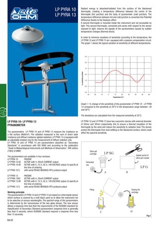
- 1. LP PYRA 10 LP PYRA 13 -3,0 -2,0 -1,0 0,0 1,0 2,0 3,0 -30 -20 -10 0 10 20 30 40 50 60 A B C D LP LP SG G EA-22 The pyranometers LP PYRA 10 and LP PYRA 13 measure the irradiance on a flat surface (Watt/m²). The radiation measured is the sum of direct solar irradiance and diffuse irradiance (global radiation). LP PYRA 13 is equipped with an adjustable shadow ring for the measurement of diffuse radiation only. LP PYRA 10 and LP PYRA 13 are pyranometers classified as “Secondary Standards” in accordance with ISO 9060 and according to the publication “Guide to Meteorological Instruments and Methods of Observation”, fifth edition (1983) of WMO The pyranometers are available in four versions: LP PYRA 10 PASSIVE LP PYRA 10 AC ACTIVE with 4..20mA CURRENT output LP PYRA 10 AV ACTIVE with 0..1V, 0..5V, 0..10V VOLTAGE output, to specify at the time of ordering LP PYRA 10 S with serial RS485 MODBUS-RTU protocol output LP PYRA 13 PASSIVE LP PYRA 13AC ACTIVE with 4..20mA CURRENT output LP PYRA 13 AV ACTIVE with 0..1V, 0..5V, 0..10V VOLTAGE output, to specify at the time of ordering LP PYRA 13 S with serial RS485 MODBUS-RTU protocol output Working principle The pyranometers LP PYRA 10 and LP PYRA 13 are based on a thermopile sensor which surface is covered by a matt black paint so to allow the instrument not to be selective at various wavelengths. The spectral range of the pyranometers is determined by the transmission of the two glass domes. The new sensor allows a response time less than the requirements of the ISO9060 standard for classification of Secondary Standard pyranometers (response time is generally less than 6 seconds, where ISO9060 standard requires a response time less than 15 seconds). Radiant energy is absorbed/radiated from the surface of the blackened thermopile, creating a temperature difference between the centre of the thermopile (hot junction) and the body of pyranometer (cold junction). The temperature difference between hot and cold junction is converted into Potential Difference thanks to the Seebeck effect. A second thermopile is mounted inside the instrument and not accessible by light. This second thermopile, connected anti-series with respect to the sensor exposed to light, reduces the signals of the pyranometers caused by sudden temperature changes (thermal shock). In order to minimize variations of sensitivity according to the temperature, the LP PYRA 10 and LP PYRA 13 are equipped with a passive compensation circuit. The graph 1 shows the typical variation of sensitivity at different temperatures. Graph 1: % change of the sensitivity of the pyranometer LP PYRA 10 - LP PYRA 13 compared to the sensitivity at 20°C in the temperature range between -20 and 50°C. The deviations are calculated from the measured sensitivity at 20°C. LP PYRA 10 and LP PYRA 13 have two concentric domes with external diameter of 50mm and 30mm respectively, this to ensure a thermal insulation of the thermopile by the wind and reduce the sensitivity to radiation heat. The domes protect the thermopile from dust settling on the blackened surface, which could affect the spectral sensitivity. LP PYRA 10- LP PYRA 13 PYRANOMETER Fig.1 Silica-gel cartridge Perforated cap Sealed sachet of silica-gel crystals Closing the cartridge Filling Temperature (C°) %sensitivityvariation
- 2. Environmentalanalysis EA-23 Installation and mounting of the pyranometers to measure global radiation: Before installing the pyranometers you need to load the cartridge containing silica gel crystals.The silica gel has the function of absorbing the humidity in the dome chamber, which can lead to condensation on the inside of the dome walls, thus altering the measure.While loading silica gel crystals, avoid touching it with wet hands. The operations to perform (as much as possible) in a dry place are: 1 unscrew the three screws that fix the white screen 2 unscrew the Silica gel cartridge by using a coin 3 remove cartridge perforated cap 4 open the envelope (included with the pyranometer) containing the silica gel 5 fill the cartridge with silica-gel crystals 6 close the cartridge with his cap,making sure that the O-ring seal is positioned correctly 7 screw the cartridge into the body of the pyranometer with a coin 8 make sure that the cartridge is firmly screwed (if not the duration of the crystals of silica gel is reduced) 9 place the screen and screw it 10 the pyranometer is ready is ready for use Figure 1 briefly describes the operations necessary for loading the cartridge with silica-gel crystals. accessible for periodic cleaning of the silicon window. At the same time you should avoid buildings, trees or obstacles of any kind exceed the horizontal plane on which the pyranometer lies. In case this is not possible it is advisable to choose a location where the obstacles are lower than 5°. N.B. the presence of obstructions on the horizontal line significantly affects the measurements of direct irradiance. project the reflection of the sun (or shadow) on the same pyranometer. so that the cable comes out from the North pole side if you use it in the NORTH hemisphere, and from the SOUTHERN pole side if you use it in the SOUTH hemisphere, according to the ISO TR9901 standard and other WMO recommendations. In any case, it is preferable to comply with WMO/ISO recommendations also when the screen is used. PYRA 13 are equipped with a spirit level, which adjustment is by two screws with lock nut that allows changing the pyranometer inclination. The fixing on a flat base can be performed by using two 6mm diam. holes and 65 mm wheelbase. In order to access the holes, remove the screen and re-place it back after mounting, see figure 2. request a range of accessories illustrated in Figure 3. The installer must take care that the height of the mast does not exceed the floor of the pyranometer, not to introduce measurement errors caused by reflections and shadows caused by the pole. there is a good electrical contact to earth. Fig.2 HD 2003.83 HD 2003.77C HD 2003.77 HD 2003.79 HD 2003.85 HD 2003.84 Fig.3 50.0 mm Fixing/mounting hole 65.0 mm 79.0 mm D 6 mm 165 mm LP PYRA 10 AC LP PYRA 10 AV LP PYRA 10 HD9906.47 HD9906.46 HD9906.46 104mm Bubble level HD9906.47 Pyranometer LP PYRA 10 with LP S1 LP S1
- 3. EA-24 Electrical Connections and Requirements for Electronic reading: LP PYRA 10 and LP PYRA 13 are produced in four versions: LP PYRA 10, LP PYRA 10AC, LP PYRA 10 AV and LP PYRA 10 S LP PYRA 13, LP PYRA 13AC, LP PYRA 13AV, and LP PYRA 13 S power. The voltage required is: 10-30 Vdc for the versions AC and AV with 0..1V and 0..5 V output. 15-30 Vdc for the version AV with 0..10V output. 5-30 Vdc for the version LP PYRA 10 S and LP PYRA 13 S with RS485 output provided with 3 wires plus braid (screen), (4 wires plus braid in the S versions). LP PYRA 10 - LP PYRA 13 Connector Function Color 1 Positive (+) Red 2 Negative (-) Blue 3 Case ( ) White 4 Screen ( ) Black LP PYRA 10 AC- LP PYRA 13AC Connector Function Color 1 Positive (+) Red 2 Negative (-) Blue 3 Case ( ) White 4 Screen ( ) Black LP PYRA 10 AV- LP PYRA 13AV Connector Function Color 1 (+) Vout Red 2 (-) Vout and (-)Vcc Blue 3 (+) Vcc White 4 Screen ( ) Black CONNECTION SCHEME LP PYRA 10 S - LP PYRA 13 S 4 5 3 2 1 6 12 3 4 5 6 7 8 Fixed 8-pole plug M12 Flying 8-pole M12 Connector Function Color 1 (-)Vcc Black 2 (+) Vcc Red 4 RS485 A/- Brown 5 RS485 B/+ White 6 Not connected Blue 8 Not connected Green acquisition system.Typically,the signal from the pyranometer does not exceed 20 mV. In order to take full advantage of the pyranometer, the recommended resolution of the reading instrument is 1 V. An example of connection to a reading system is shown in Figure 6. a multimeter as shown below (Figure 7), resistance load for reading the signal must be ≤ 500 Ω: a multimeter, as shown below (Figure 8), the load resistance for reading the signal must be ≥ 100 kΩ: 2 3 1 4 12 3 4 Fig.4 Red [ ]1 Blue [ ]2 Black [ ]4 White [ ]3 Probe output = µV/(W/m ) 2 12 3 4 (schield) Converter/Amplifier with or outputV mA Datalogger or Fig.6 Red [ ]1 Equipment with 4...20 mA input Blue [ ]2 White [ ]3 Power supply 10...30 Vdc 4...20 mA Probe output = 4...20 mA 12 3 4 Black [ ]4 (schield) Fig.7 Red [ ]1 Blue [ ]2 Black [ ]4 White [ ]3 Probe output = 0...1V, 0...5V, 0...10 V (schield) 12 3 4 Power Supply Equipment with 0...1V/0...5V/0...10V input 10...30 Vdc for other versions 15...30 Vdc for 0÷10V output Fig.8
- 4. CPM 12 AA4... LP PYRA 10 LP SP1 LP PYRA 10 Environmentalanalysis EA-25 LP PYRA ... S has to be connected according to the following scheme: Maintenance: In order to ensure a high measurement accuracy, it is necessary to keep the external dome, so the higher the frequency of cleaning, the best measurement accuracy will be. Cleaning can be done with normal tissue for cleaning photographic objectives and water, if not possible, simply use pure ethyl alcohol. After cleaning with alcohol, it is necessary also to clean the dome again with water only. Due to the high temperature fluctuations between day and night, it is possible that you get some condensation inside the pyranometer dome; in this case the reading done is strongly overestimated. To minimize condensation inside the pyranometer, a cartridge of Silica gel is placed inside the instrument. The efficiency of silica-gel crystals decreases over time with the absorption of moisture. When crystals of silica gel are efficient their colour is yellow, while when they gradually lose efficiency, their colour becomes white/transparent; to replace them, please refer to the instructions at paragraph Installation of pyranometers. Silica gel typically lifetime goes from 4 to 12 months according to the environmental conditions where the pyranometer is installed. Calibration and measures: LP PYRA 10, LP PYRA 13 The sensitivity of the pyranometer S (or calibration factor) allows to determine the global irradiance by measuring a volt signal at the end of the thermopile. The S factor is in μV/(Wm-2 ). Once measured the potential difference (DDP) at the ends of the thermopile, the radiation Ee is obtained by the following formula: Ee= DDP/S where; Ee: is the Radiation expressed in W/m2 , DDP: is the difference of potential expressed in μV measure by a multimeter, LP PYRA 10 AC, LP PYRA13AC The sensitivity of the pyranometer is factory adjusted so that 4..20 mA = 0.. 2000 W/m2 (on request 0…4000 W/m2 ). To get the value of radiation once the current (Iout) absorbed by the instrument is known, following formula has to be applied: Ee = 125∙(Iout-4mA) where; Ee: is the Radiation expressed in W/m2 , Iout: is the current in mA absorbed by the instrument LP PYRA 10 AV, LP PYRA 13AV The sensitivity of the pyranometer is factory adjusted, so as to have, depending on the version that has been chosen: 0..1 V = 0.. 2000 W/m2 (on request 0...4000 W/m²) 0..5 V = 0.. 2000 W/m2 (on request 0...4000 W/m²) 0..10 V = 0.. 2000 W/m2 (on request 0...4000 W/m²) To obtain the value of irradiation, once the output voltage (Vout) of the instrument is known, following formula has to be applied: Ee = 2000 [(W/m2 )/V] x Vout [V] for the version 0…1V (0…2000 W/m2 ) Ee = 400 [(W/m2 )/V] x Vout [V] for the version 0…5V (0…2000 W/m2 ) Ee = 200 [(W/m2 )/V] x Vout [V] for the version 0…10V (0…2000 W/m2 ) where; Ee : is the Radiation expressed in W/m2 , Vout : is the output voltage (in Volts) measured with the voltmeter Each pyranometer is individually factory calibrated and is distinguished by its calibration factor. To take full advantage of the LP PYRA 10 and LP PYRA 13 features, we recommend performing the calibration annually. The instruments present in the metrology laboratory of Photo-Radiometry at Delta Ohm srl allows the calibration of the pyranometer according to the requirements of WMO, and ensures the traceability of measurements to international standards. Specifications: Typical sensitivity: LP PYRA 10 - LP PYRA 13 10 μV/(W/m²) LP PYRA 10AC - LP PYRA 13AC 4..20 mA (0...2000 W/m²) 4...20mA (0...4000W/m²) on request LP PYRA 10AV - LP PYRA 13AV 0..1,5,10V (0...2000 W/m²) 0...1,5,10V (0...4000W/m2 ) on request Impedance: 5 Ω ÷ 50 Ω Measuring range: 0-4000 W/m² Field of view: 2 sr Spectral range: 283 nm ... 2800 nm (50%) Working temperature: -40 °C ... 80 °C Dimensions: figure 1 Weight: 0.90 Kg Shadow ring of LP PYRA 13 Weight 5.90 Kg Diameter of the ring 570mm Height of the ring 54mm Diameter of the base 300mm Specifications according to ISO 9060 1- Response time: <6 sec (95%) 2- Off-set Zero: a) response to a thermal radiation of 200W/m2 : <7 W/m2 b) response to a change of 5K/h in the room temperature: <|±2|W/m2 3a- Long-term instability: <|±0.8| % (1 year) 3b- Nonlinearity: <|±0.5| % 3c- Response according to Cosine law: < |÷10| W/m2 3d- Spectral selectivity: < |±3| % 3e- Temperature response: <2 % 3f- Tilt response: <|0.5| % B/+ A/- GND GND +5Vdc 220Ω 220Ω ShieldShield Lmax = 1200m 390Ω 390Ω B/+ B/+ GND +Vcc A/- A/- +Vdc LP PYRA ... S 5 4 1 2 Terminal end Terminal end Other sensors with RS485 output PLC, data logger and RS485/USB converter for PC Power supply 5...30Vdc
- 5. LP PYRA 10 + HD2003.77C + HD2003.77 HD2003.77C HD2003.71K CPM 12AA4... LP PYRA 10 HD2003.84.1 HD2003.83 HD2003.83.1 HD2003.77 EA-26 PURCHASING CODE LP PYRA 10: Secondary Pyranometer according to ISO 9060. Equipped with protection, silica-gel crystals cartridge, 2 recharges, level, 4-poles M12 connector and Report of Calibration ISO9001. LP PYRA 10 AC: Secondary Pyranometer according to ISO 9060. Equipped with protection, silica-gel crystals cartridge, 2 recharges, level, 4-poles M12 connector and Report of Calibration ISO9001. 4...20mA current output signal (0...2000W/m²). 4...20mA (0...4000W/m² on request). LP PYRA 10 AV: Secondary Pyranometer according to ISO 9060. Equipped with protection, silica-gel crystals cartridge, 2 recharges, level, 4-poles M12 connector and Report of Calibration ISO9001. Voltage 0..1Vdc, 0..5Vdc, 0..10Vdc output signal, to define when ordering (0...2000W/m²). 0..1V, 0...5V, 0...10V (0...4000W/m²) on request. LP PYRA 10 S: Secondary Pyranometer according to ISO 9060. Equipped with protection, silica-gel crystals cartridge, 2 recharges, level, M12 8-pole connector and Report of Calibration. Connection cable CPM12-8P… with M12 connector with 2, 5 or 10m length have to be ordered separately. Serial output RS485 MODBUS-RTU. Power supply: 5…30Vdc. LP PYRA 13: Secondary Pyranometer according to ISO 9060. Equipped with protection, shadow ring for diffuse radiation, silica-gel crystals cartridge, 2 recharges,level,4-poles M12 connector and Report of Calibration ISO9001. LP PYRA 13 AC: Secondary Pyranometer according to ISO 9060. Equipped with protection, shadow ring for diffuse radiation, silica-gel crystals cartridge, 2 recharges,level,4-poles M12 connector and Report of Calibration ISO9001. 4...20mA current output signal (0...2000W/m²). 4...20mA (0...4000W/m²) on request. LP PYRA 13 AV: Secondary Pyranometer according to ISO 9060. Equipped with protection, shadow ring for diffuse radiation, silica-gel crystals cartridge, 2 recharges,level,4-poles M12 connector and Report of Calibration ISO9001. Voltage 0..1Vdc, 0..5Vdc, 0..10Vdc output signal, to define when ordering (0...2000W/m²). 0..1V, 0...5V, 0...10V (0...4000W/m²) on request. LP PYRA 13 S: Secondary Pyranometer according to ISO 9060. Equipped with protection, shadow ring for diffuse radiation, silica-gel crystals cartridge, 2 recharges, level, M12 8-pole connector and Report of Calibration. Connection cable CPM12-8P… with M12 connector with 2, 5 or 10m length have to be ordered separately. Serial output RS485 MODBUS-RTU. Power supply: 5…30Vdc. CPM12 AA4.2: 4-pole cable. Length 2m. 4-pole M12 connector on one end, open wires on the other side CPM12 AA4.5: 4-pole cable. Length 5m. 4-pole M12 connector on one end, open wires on the other side CPM12 AA4.10: 4-pole cable. Length 10m. 4-pole M12 connector on one end, open wires on the other side CPM12-8P.2: 8-pole cable. Length 2m. 8-pole M12 connector on one end, open wires on the other side (only for LP PYRA…S) CPM12-8P.5: 8-pole cable. Length 5m. 8-pole M12 connector on one end, open wires on the other side (only for LP PYRA…S) CPM12-8P.10: 8-pole cable. Length 10m. 8-pole M12 connector on one end, open wires on the other side (only for LP PYRA…S) CP 24: PC connecting cable for the RS485 MODBUS parameters configuration of the LP PYRA…S pyranometers. With built-in RS485/USB converter. 8-pole M12 connector on instrument side and A-type USB connector on PC side. Supplied with a CD-ROM including the USB drivers and a software for the Modbus connection to PC. HD 2003.85: Mounting kit with adjustable height for the installation of the pyranometer on pole with diameter Ø 40 mm (HD2003.84 + HD2003.85 + HD2003.79) HD 2003.79: Mounting kit pyranometer on clamping Ø 40mm (HD2003.77 + HD2003.79) HD 2003.77: Clamping for mast Ø 40mm LP SP1: Protective screen plastic UV resistant. LURAN S777K by BASF® LP S1: Bracket positioning pyranometer LP PYRA 10, suitable for pole with a maximum diameter of 50mm. LP RING 02: Base with levelling device and adjustable holder for mounting the LP PYRA 10 pyranometers in an inclined position. LP S6: Kit for the installation of LP PYRA 10 pyranometers. The kit includes: 1 m mast (LP S6.05), base fitting (LP S6.04), graduated support plate (LP S6.01), bracket for HD9007 or HD32MTT.03.C (HD 9007T29.1), bracket for pyranometers (LP S6.03). LP SG: Cartridge containing silica gel crystals, complete with O-ring and cap. LP G: Pack of 5 cartridges of silica gel crystals. B AC D ++ - - Thermopile Thermopile Case Discharger Blue Red White Shield (Black) LP PYRA 10 - LP PYRA 13 Temperature compesation Fig.5