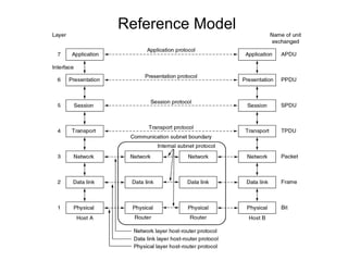
2. Data Link layer
• Data link Layer
– explicit in OSI
– can be synchronous or asynchronous
• Reliable & Efficient Data Transfer
(over a point-to-point link)
– Error Detection, Error Recovery, Flow Control
• Protocol performance governed by
– propagation delay
– bit-rate & frame size
– noise
• Provide service interface to the network layer
• Regulating data flow
– Slow receivers not swamped by fast senders
3.
4.
5. (a) Virt ual c o m m u n ic atio n.
(b) Act u al c o m m u n icatio n.
6.
7. Services offered to Network Layer
• Unacknowledged connectionless service
– Sender has no way of knowing if a frame has been successfully
delivered
– No logical connection is established
– Appropriate for low error rate and real-time traffic
– Losses are taken care at higher levels
– Used on reliable medium like coax cables or optical fiber, where
the error rate is low.
– Appropriate for voice, where delay is worse than bad data.
– Most LANs use it
8. Acknowledged Connectionless
service
• Useful on unreliable medium like wireless.
• Acknowledgements add delays.
• Adding ack in the DLL rather than in the NL is just an
optimization and not a requirement. Leaving it for the NL
is inefficient as a large message (packet) has to be
resent in that case in contrast to small frames here.
• On reliable channels, like fiber, the overhead associated
with the ack is not justified.
• No logical connection still, but each individual frame is
acknowledged
• Appropriate for WLANs
9. Acknowledged Connection-oriented
service
• Most reliable,
• Guaranteed service
– Each frame sent is indeed received
– Each frame is received exactly once
– Frames are received in order
• Special care has to be taken to ensure
this in connectionless services
10. End to End
ACK/NAK
1 2 3 4 5
Data Data Data Data
Hop by Hop
Data Data Data Data
1 2 3 4 5
ACK/ ACK/ ACK/ ACK/
NAK NAK NAK NAK
12. Data Link Frames
• Start and End of frames need to be
identified at the destination, so they
should be marked
– Character counts
– Start and ending flags with bit stuffing
– Flag bytes with byte stuffing
– Physical layer coding violation
13. Framing with Character Count
A character stream. (a) Without errors. (b) With
one error.
14. Problem with Framing with CC
• What if the count is garbled
• Even if with checksum, the receiver knows
that the frame is bad there is no way to tell
where the next frame starts.
• Asking for retransmission doesn’t help
either because the start of the
retransmitted frame is not known
• No longer used
15. Framing with bit stuffing
Bit stuffing
(a) The original data.
(b) The data as they appear on the line.
(c) The data as they are stored in receiver’s memory after
destuffing.
17. Framing with byte stuffing
• Problem : fixed character size : assumes
character size to be 8 bits : can’t handle
heterogeneous environment.
18. Physical Layer coding
violations
• Some LANs encode 1 bit of data by using 2
physical bits
– Normally, a 1 bit is a high-low pair and a 0 bit is a
low-high pair
– The start/end of a frame could be represented by
the signal low-low or high-high
• The advantage is that no extra bandwidth is
required as in byte stuffing
• The IEEE 802.4 standard uses this approach
19. Types of Errors
• Single-Bit Error
– only one bit in the data unit has changed
• Burst Error
– 2 or more bits in the data unit have changed
• Error Correcting Codes
– Include enough redundancy to detect and correct
errors
– appropriate for unreliable channels
• Error Detecting Codes
– Include enough redundancy bits to detect errors and
use
– ACKs and retransmissions to recover from the
errors
– Appropriate for reliable channels
20.
21. Error Detection and Correction
• In some cases it is sufficient to detect an
error and in some, it requires the errors to
be corrected also. For eg.
– On a reliable medium : ED is sufficient where
the error rate is low and asking for
retransmission after ED would work efficiently
– In contrast, on an unreliable medium :
Retransmission after ED may result in another
error and still another and so on. Hence EC is
desirable.
22. Redundancy
• Error detection uses the concept of
redundancy, which means adding extra
bits for detecting errors at the
destination
26. Note:
• In parity check, a parity bit is added to every
data unit so that the total number of 1s is
even (or odd for odd-parity).
• This method is called Vertical Redundancy
Check
27. Example 1
• Suppose the sender wants to send the word world. In ASCII
the five characters are coded as
1110111 1101111 1110010 1101100 1100100
• The following shows the actual bits sent
11101110 11011110 11100100 11011000 11001001
• Now suppose the word world in Example 1 is received by
the receiver without being corrupted in transmission.
11101110 11011110 11100100 11011000 11001001
•The receiver counts the 1s in each character and comes up
with even numbers (6, 6, 4, 4, 4). The data are accepted.
28. • Now suppose the word world in Example 1
is corrupted during transmission.
• 11111110 11011110 11101100
11011000 11001001
• The receiver counts the 1s in each character
and comes up with even and odd numbers
(7, 6, 5, 4, 4). The receiver knows that the
data are corrupted, discards them, and
asks for retransmission.
29. Note:
• Simple parity check can detect all
single-bit errors. It can detect burst
errors only if the total number of errors
in each data unit is odd.
30. LRC
• In two-dimensional parity check, a
block of bits is divided into rows and a
redundant row of bits is added to the
whole block.
32. Example 2
• Suppose the following block is sent:
10101001 00111001 11011101 11100111
10101010
• However, it is hit by a burst noise of length 8,
and some bits are corrupted.
10100011 10001001 11011101 11100111
10101010
• When the receiver checks the parity bits, some
of the bits do not follow the even-parity rule and
the whole block is discarded.
10100011 10001001 11011101 11100111
10101010
39. Checksum
• The sender follows these steps:
– The unit is divided into k sections, each of n
bits.
– All sections are added using one’s
complement to get the sum.
– The sum is complemented and becomes the
checksum.
– The checksum is sent with the data.
40. Checksum
• The receiver follows these steps:
– The unit is divided into k sections, each of n
bits.
– All sections are added using one’s
complement to get the sum.
– The sum is complemented.
– If the result is zero, the data are accepted:
otherwise, rejected.
41. Checksum
• Suppose the following block of 16 bits is to be
sent using a checksum of 8 bits.
10101001 00111001
• The numbers are added using one’s
complement
10101001
00111001
------------
Sum 11100010
• Checksum 00011101
• The pattern sent is 10101001 00111001
00011101
42. Checksum
• Now suppose the receiver receives the pattern
sent in Example and there is no error.
10101001 00111001 00011101
• When the receiver adds the three sections, it will
get all 1s, which, after complementing, is all 0s
and shows that there is no error.
• 10101001
• 00111001
• 00011101
• Sum 11111111
• Complement 00000000 means that the
pattern is OK.
43. Checksum
• Now suppose there is a burst error of length 5 that
affects 4 bits.
10101111 11111001 00011101
• When the receiver adds the three sections, it gets
10101111
11111001
00011101
• Partial Sum 1 11000101
• Carry 1
• Sum 11000110
• Complement 00111001 the pattern is corrupted.
44. Correction
• Backword Error Control
– Retransmission
• Forward Error Control
– Single bit Error Correction
– Burst Error Correction
45. Hamming Codes : for ED n EC
• m data bits together with r error check bits form
an n = (m + r) bit codeword
• The number of bits two codeword differ in is
called the hamming distance between the two
codeword
• Significance : If two codeword are at HD d then it
requires d single bit errors to convert one into
the other
46. HD of a coding scheme
• For m bit data .. All the 2^m possible combinations are
legal
• But not all the 2^m codewords are used
-- in a coding scheme (algorithm to compute the check
bits) some of these codewords are legal and others are
illegal
For eq .. Consider parity : 1(r = 1) parity bit is appended
with value so that the total number of 1’s in the codeword
is even ..
Then 11011 is a legal codeword in this scheme but 11010
is not
47. Use of HD for error detection
• To detect d single bit errors , we need (an
algorithm that creates) a code list with HD at
least d + 1
For eg . For the parity scheme .. HD is 2 ..hence it
can be used to detect single bit errors (d=1)
• If the recvd codeword is legal .. We accept it ,
• And if it is illegal we report (detect) an error
Remember : Each algorithm to compute the check
bits create a different list of legal codewords
48. Data and redundancy bits
Hamming Code
Number of Number of Total
data bits redundancy bits bits
m r m+r
1 2 3
2 3 5
3 3 6
4 3 7
5 4 9
6 4 10
7 4 11
54. Flow and Error Control
• Flow Control
Flow control refers to a set of procedures used to
restrict the amount of data that the sender can
send before waiting for acknowledgment.
• Error Control
Error control in the data link layer is based on
automatic repeat request, which is the
retransmission of data (Backward Error Control).
55. Flow Control
• Ensure sending entity does not overwhelm
receiving entity
– By preventing buffer overflow
• Influenced by:
– Transmission time
• time taken to emit all bits into medium
– Propagation time
• time for a bit to traverse the link
• Assume here no errors but varying delays
56. Stop and Wait Flow Control
• Source transmits frame
• Destination receives frame and replies
with acknowledgement (ACK)
• Source waits for ACK before sending next
• Destination can stop flow by not send ACK
• Works well for a few large frames
• Stop and wait becomes inadequate if large
block of data is split into small frames
57. Sliding Windows Flow Control
• Allows multiple numbered frames to be in transit
• Receiver has buffer W long
• Transmitter sends up to W frames without ACK
• ACK includes number of next frame expected
• Receiver can ack frames without permitting
further transmission (Receive Not Ready)
• Must send a normal acknowledge to resume
• If have full-duplex link, can piggyback ACks
58.
59.
60. Error Control
• Detection and correction of errors such as:
– Lost frames
– Damaged frames
• Common techniques use:
– Error detection
– Positive acknowledgment
– Retransmission after timeout
– Negative acknowledgement & retransmission
61. Elementary Data Link Protocols
• An Unrestricted Simplex Protocol
• A Simplex Stop-and-Wait Protocol
• A Simplex Protocol for a Noisy
Channel
62. An Unrestricted Simplex Protocol
• Transmitting and receiving NW layers are
always ready
• Simplex transmission
• Processing time ignored
• Infinite buffer space
• Error free channel
• No sequence numbers and ACKs used
• Sender
– Fetch a packet, construct a frame, send the
frame
• Receiver
– Receives the undamaged frame from the
physical layer.
63. A Simplex Stop-and-Wait Protocol
• Communication in one direction
• Channel is assumed to be error free
• Deals with
– preventing the sender from flooding the receiver with
data faster than later is able to process them
• ACK is used
– Sender sends data frame
– Receiver sends ACK (dummy frame)
– Sender sends the next frame
65. Stop and Wait
• Source transmits single frame
• Wait for ACK
• If received frame damaged, discard it
– Transmitter has timeout
– If no ACK within timeout, retransmit
• If ACK damaged,transmitter will not
recognize it
– Transmitter will retransmit
– Use alternate numbering and ACK0 / ACK1
68. Stop-and-Wait ARQ, delayed ACK
• In Stop-and-Wait ARQ, numbering frames prevents the
retaining of duplicate frames
• Numbered acknowledgments are needed if an
acknowledgment is delayed and the next frame is lost
69. Sliding Windows Flow Control
• Allows multiple numbered frames to be in transit
• Receiver has buffer W long
• Transmitter sends up to W frames without ACK
• ACK includes number of next frame expected
• Receiver can ack frames without permitting
further transmission (Receive Not Ready)
• Must send a normal acknowledge to resume
• If have full-duplex link, can piggyback ACks
70. Piggybacking
• To increase the utilization of the link
• Frames in reverse direction carry the
Ack for received frames
– No separate frames for Ack
72. Go-Back-N ARQ
• Based on sliding window
• If no error, ACK as usual
• Use window to control number of
outstanding frames
• If error, reply with rejection
– Discard that frame and all future frames until
error frame received correctly
– Transmitter must go back and retransmit that
frame and all subsequent frames
73. Go Back N - Handling
• Damaged Frame
– Error in frame i so receiver rejects frame i
– Transmitter retransmits frames from i
• Lost Frame
– Frame i lost and either
• Transmitter sends i+1 and receiver gets frame i+1
out of seq and rejects frame i
• Or transmitter times out and send ACK with P bit
set which receiver responds to with ACK i
– Transmitter then retransmits frames from i
74. Go Back N - Handling
• Damaged Acknowledgement
– Receiver gets frame i, sends ack (i+1) which is lost
– Acks are cumulative, so next ack (i+n) may arrive
before transmitter times out on frame i
– If transmitter times out, it sends ack with P bit set
– Can be repeated a number of times before a reset
procedure is initiated
• Damaged Rejection
– Reject for damaged frame is lost
– Handled as for lost frame when transmitter times out
75. Go-Back-N ARQ
In Go-Back-N ARQ, the size of the sender
window must be less than 2m; the size
of the receiver window is always 1.
82. Selective-Repeat ARQ
• Also called selective reject ARQ
• Only rejected frames are retransmitted
• Subsequent frames are accepted by the receiver
and buffered
• Minimizes retransmission
• Receiver must maintain large enough buffer
• More complex logic in transmitter
• Hence less widely used
• Useful for satellite links with long propagation
delays