SlideShare una empresa de Scribd logo
1 de 11
Descargar para leer sin conexión
SE30A-AC Series 
SE30A40AC SERIES BRUSHLESS SERVO AMPLIFIERS 
Models: SE10A40AC, SE30A40AC 
Sold & Serviced By: 
ELECTROMATE 
Toll Free Phone (877) SERVO98 
Toll Free Fax (877) SERV099 
www.electromate.com 
sales@electromate.com 
FEATURES: 
• Surface-mount technology 
• Small size, low cost, ease of use 
• Optical isolation, see block diagram 
• DIP switch selectable modes: 
current or encoder velocity 
• Four quadrant regenerative operation 
• Encoder interface for sinusoidal commutation 
• AC Supply Operation 
• Agency Approvals: 
BLOCK DIAGRAM:
Sold & Serviced By: 
ELECTROMATE 
SE30A-AC Series 
Toll Free Phone (877) SERVO98 
Toll Free Fax (877) SERV099 
DESCRIPTION: The SE30A40AC Series PWM servo amplifiers are designed to drive brushless motors with 3 phase sine 
wave current. An on board digital controller generates the 3 phase sine wave signals from an optical "incremental 
encoder". Although encoders are used for the sinusoidal commutation, Hall sensors are required for the start up routine. 
This model is fully protected against over-voltage, under-voltage, over-current, over-heating and short-circuits. This 
model interfaces with digital controllers or can be used as a stand-alone drive. The SE30A40AC series requires a single 
or three-phase AC power supply. A red/green LED and two digital outputs indicate operating status. Loop gain, current 
limit, input gain and offset can be adjusted using 14-turn potentiometers. The offset adjusting potentiometer can also be 
used as an on-board input signal for testing purposes when SW1 (DIP switch) is ON. 
SPECIFICATIONS: 
All SE10A40AC and SE30A40AC specifications are respectively identical to the SE10A40 and SE30A40 specifications 
(see SE30A40 series data sheets) except for: 
www.electromate.com 
sales@electromate.com 
D-58 
MODEL 
POWER STAGE SPECIFICATIONS SE10A40AC* SE30A40AC 
AC SUPPLY VOLTAGE 45-270 VAC, 1 or 3 phase, 50-60 Hz 
CONTINUOUS DC CURRENT AVAILABLE FROM 
INTERNAL SUPPLY ** 
30 A for three phase AC input 
15 A for single phase AC input 
PEAK DC CURRENT AVAILABLE FROM INTERNAL 
SUPPLY (MAXIMUM 2 SECONDS) ** 
60 A for three phase AC input 
30 A for single phase AC input 
INTERNAL SHUNT RESISTOR 30 Ω @ 50 W 
SHUNT SWITCH-ON VOLTAGE ** 390 V 
BUS CAPACITANCE 1980 μF 
SHUNT FUSE (d=.25 inches, L=1.25 inches) 3 A Motor Delay rated @ 250 VAC 
AC LINE FUSES (d=.25 inches, L=1.25 inches) 15 A slow blow rated @ 250 VAC 
MECHANICAL SPECIFICATIONS 
AC CONNECTOR: C1 Screw terminals 
DC OUT AND EXTERNAL SHUNT CONNECTOR: C2* Screw terminals 
MOTOR CONNECTOR: P3 Screw terminals 
SIGNAL CONNECTORS: P1, P2 
AMP 748390-6, AMP 748481-6 
P1 is a 26 pin high density female D-sub connector and 
P2 is a 15 pin high density female D-sub connector. 
SIZE 
8.00 x 6.52 x 4.06 inches 
203.2 x 165.7 x 103.1 mm 
WEIGHT 
4.94 Lb. 
2.23 Kg 
* The internal bus voltage is available on C2 to power DC supply units. 
** If the shunt regulator is disabled the shut down voltage is 420 VDC.
SE30A-AC Series 
Sold & Serviced By: 
ELECTROMATE 
Toll Free Phone (877) SERVO98 
Toll Free Fax (877) SERV099 
www.electromate.com 
sales@electromate.com 
These amplifiers contain a rectifier bridge and filter capacitors to generate the DC bus internally from the AC input power. 
The DC bus voltage is 1.4 times AC voltage (RMS), e.g. 310 VDC from 220 VAC. During braking much of the stored 
mechanical energy is fed back into the power supply and charges the bus capacitor to a higher voltage. If this voltage 
reaches the amplifier’s over-voltage shutdown point, output current and braking will cease. To ensure smooth braking of 
large inertial loads, a built-in “shunt regulator” is provided in the SE30A40AC. The shunt regulator will switch on the 
internal power resistor when the bus voltage reaches 390 VDC. This allows the bus capacitor to discharge and thus 
lower the bus voltage. During regeneration, the regeneration LED will blink (solid green is non-regeneration mode). An 
external shunt resistor can be added in parallel to the internal resistor (between C2-3 and C2-4). Recommended value is 
20 ohms with a minimum 100 W rating. Removing the jumper between C2-4 and C2-5 will disable the internal shunt 
resistor. If the shunt regulator becomes inoperative the over voltage protection on the amplifier will disable the drive if the 
regeneration energy causes the bus voltage to exceed 425 VDC. 
D-59 
ORDERING INFORMATION: 
Models: SE10A40AC and SE30A40ACX 
*Divide by 4 option 
Models: SE10A40AC-4 and SE30A40ACX-4 
*Divide by 8 option 
Models: SE10A40AC-8 and SE30A40ACX-8 
*Divide by 16 option 
Models: SE10A40AC-16 and SE30A40ACX-16 
*For use with high-resolution encoders, contact the factory to determine which option is best for your application 
X indicates current revision letter. 
MATING CONNECTORS: 
Manufacturer: AMP (Tel: 1-800-522-6752) 
Part numbers: 
15 Pin plug 748364-1 
26 Pin plug 748365-1 
Pins 748333-2 
Shell Kit (plastic with metal coating) 
15 Pin 748677-1 
26 Pin 748677-2 
TYPICAL SYSTEM WIRING: See section “G”. 
MOUNTING DIMENSIONS: See page F-14.
SE30A Series 
D-45 
SE30A SERIES BRUSHLESS SERVO AMPLIFIERS 
Models: SE10A8, SE10A20, SE10A40, SE30A8, SE30A20, SE30A40 
Sold & Serviced By: 
ELECTROMATE 
Toll Free Phone (877) SERVO98 
Toll Free Fax (877) SERV099 
www.electromate.com 
sales@electromate.com 
FEATURES: 
• Surface-mount technology 
• Small size, low cost, ease of use 
• Optical isolation, see block diagram 
• DIP switch selectable modes: 
current, encoder velocity, external 
velocity, tachometer 
• Four quadrant regenerative operation 
• Encoder interface for sinusoidal commutation 
• Agency Approvals: 
BLOCK DIAGRAM: 
ADVANCED MOTION CONTROLS 
3805 Calle Tecate, Camarillo, CA 93012 Tel: (805) 389-1935, Fax: (805) 389-1165
Sold & Serviced By: 
ELECTROMATE 
SE30A Series 
Toll Free Phone (877) SERVO98 
Toll Free Fax (877) SERV099 
DESCRIPTION: The SE30A20 Series PWM servo amplifiers are designed to drive brushless motors with 3 phase sine 
wave current. An on board digital controller generates the 3 phase sine wave signals from an optical "incremental 
encoder". Although encoders are used for the sinusoidal commutation, Hall sensors are required for the start up routine. 
This model is fully protected against over-voltage, under-voltage, over-current, over-heating and short-circuits. This model 
interfaces with digital controllers or can be used as a stand-alone drive. The SE30A20 series amplifiers require only a 
single unregulated DC power supply. A red/green LED and two digital outputs indicate operating status. Loop gain, 
current limit, input gain and offset can be adjusted using 14-turn potentiometers. The offset adjusting potentiometer can 
also be used as an on-board input signal for testing purposes when SW1 (DIP switch) is ON. 
SPECIFICATIONS: 
www.electromate.com 
sales@electromate.com 
D-46 
MODEL 
POWER STAGE 
SPECIFICATIONS SE10A8* SE10A20* SE10A40 SE30A8* SE30A20* SE30A40 
DC SUPPLY VOLTAGE 20-80 V 60-190 V 60-400 V 20-80 V 60-190 V 60-400 V 
PEAK CURRENT (2 sec. Max., 
internally limited) 
±10 A 
(7.1 Arms) 
±10 A 
(7.1 Arms) 
±10 A 
(7.1 Arms) 
±30 A 
(21.2 Arms) 
±30 A 
(21.2 Arms) 
±30 A 
(21.2 Arms) 
MAXIMUM CONTINUOUS 
CURRENT (internally limited) 
±5 A 
(3.5 Arms) 
±5 A 
(3.5 Arms) 
±5 A 
(3.5 Arms) 
±15 A 
(10.6 Arms) 
±15 A 
(10.6 Arms) 
±15 A 
(10.6 Arms) 
MINIMUM LOAD INDUCTANCE 
* 200 μH 250 μH 600 μH 200 μH 250 μH 600 μH 
SWITCHING FREQUENCY 20 kHz nominal 
HEATSINK (BASE) 
TEMPERATURE RANGE 0o to +65o C, disables if > 65o C 
POWER DISSIPATION AT 
CONT. CURRENT 20 W 50 W 100 W 60 W 145 W 300 W 
OVER-VOLTAGE SHUT-DOWN 
(self reset) 84 V 195 V 425 V 84 V 195 V 425 V 
BANDWIDTH (load dependent) 2.5 kHz 
MECHANICAL SPECIFICATIONS 
POWER CONNECTOR: P3 Screw terminals 
SIGNAL CONNECTORS: P1, P2 P1 is a 26 pin high density female D-sub connector and 
P2 is a 15 pin high density female D-sub connector. 
SIZE 
8.00 x 5.62 x 1.60 inches 
203.2 x 142.9 x 40.7 mm 
WEIGHT 
2.12 lb. 
0.99 Kg 
* Low inductance motors require external inductors.
SE30A Series 
Sold & Serviced By: 
ELECTROMATE 
Toll Free Phone (877) SERVO98 
Toll Free Fax (877) SERV099 
PIN FUNCTIONS: 
CONNECTOR PIN NAME DESCRIPTION / NOTES I/O 
1 +10V @ 3 mA For customer use O 
2 SIGNAL GND Reference ground SGND 
3 -10V @ 3 mA For customer use O 
4 +REF 
5 -REF 
D-47 
Differential reference input, maximum ±15V, 20K input resistance I 
6 Velocity Input 
Single ended reference input, external velocity signal, maximum ±15V, 10K 
input resistance 
I 
7 Velocity Monitor SW2-3=OFF; 1 V = 25 kHz Encoder frequency, maximum 250 KHz 
SW2-3=ON; 1 V = 175 kHz Encoder frequency, maximum 1.75 MHz 
O 
8 Current Monitor 
This signal is proportional to the RMS current in the motor leads. Models 
SE10A: 1V = 1.33 A Models SE30A: 1V = 4 A O 
9 Current Reference 
This is the command signal to the internal current-loop. The maximum peak 
current rating of the amplifier always equals 7.25 V at this pin. 
Models SE10A: SW1-3=ON, 7.25V=10A; SW1-3=OFF, 7.25V=5A. 
Models SE30A: SW1-3=ON, 7.25V=30A; SW1-3=OFF, 7.25V=15A. 
O 
10 Phase TTL level output: Output is low when commutating in trapezoidal mode and 
will be high when the amplifier is commutating sinusoidally. O 
11 Inhibit/Enable 
This TTL level input signal turns off all power devices of the “H” bridge 
when pulled to ground with SW1-6=ON. If SW1-6 = OFF pulling this pin 
to ground will enable the amplifier. This inhibit will cause a fault condition 
and a red LED. For inverted inhibit inputs, see section "G". 
I 
12 +Inhibit/Enable I 
13 -Inhibit/Enable 
If SW1-6=ON, pull P1-12 to ground to inhibit (+) amplifier output and P1- 
13 to inhibit (-) amplifier output. 
If SW1-6=OFF, pull P1-12 to ground to enable (+) amplifier output and P1- 
13 to enable (-) amplifier output. 
These inputs will NOT cause a fault condition or a red LED. I 
14 Fault (LED red) 
TTL level output. Becomes high during output short circuit, over-voltage, 
inhibit, over-temperature and during power-on reset. Fault condition 
indicated by red LED. 
O 
15 +5V @ 250mA For customer use. Note: the total current on P1-15 and P2-13 combined 
should not exceed 250 mA. 
O 
16 SIGNAL GND Reference ground SGND 
17 Controller Power* Connected to P2-15. For customer use I 
18 Controller Line 1* Connected to P2-10. For customer use I 
19 Controller Line 2* Connected to P2-11. For customer use I 
20 Encoder Channel A+ 
Encoder Output (from connector P2) O 
21 Encoder Channel A-Differential 
22 Encoder Channel B+ 
23 Encoder Channel B-Differential 
Encoder Output (from connector P2) O 
24 Index+ 
25 Index- 
Differential Encoder Output (from connector P2) O 
www.electromate.com 
sales@electromate.com 
P1 
26 Reserved 
NOTE: All circuits on connectors P1 and P2 are optically isolated fromall circuits on connector P3. 
* No connection internal to the amplifier. See block diagram.
Sold & Serviced By: 
ELECTROMATE 
SE30A Series 
Toll Free Phone (877) SERVO98 
Toll Free Fax (877) SERV099 
www.electromate.com 
sales@electromate.com 
PIN FUNCTIONS: 
CONNECTOR PIN NAME DESCRIPTION / NOTES I/O 
D-48 
1 HALL 1 
2 HALL 2 
3 HALL 3 
Hall sensor inputs, internal 2K pull-up, logic levels: 
maximum low level input is 1.5VDC, minimum high 
level input is 3.5VDC 
I 
4 Encoder Channel A+ 
5 Encoder Channel A-Differential 
Encoder Input I 
6 Encoder Channel B+ 
7 Encoder Channel B- Differential Encoder Input I 
8 Encoder Channel I+ 
Encoder Input (Not Required) I 
9 Encoder Channel I-Differential 
10 Controller Line 1* Connected to P1-18. For customer use. O 
11 Controller Line 2* Connected to P1-19. For customer use. O 
12 Signal GND Reference ground SGND 
13 +5V @ 250mA For customer use. Note: the total current on P1-15 
and P2-13 combined should not exceed 250 mA. O 
14 TACH 
Tachometer Input, 60 KΩ input resistance, ± 60 V 
max. I 
P2 
15 Controller power* Connected to P1-17. For customer use. O 
1 MOTOR A Motor phase A connection O 
2 MOTOR B Motor phase B connection O 
3 MOTOR C Motor phase C connection O 
4 POWER GND Power ground PGND 
P3 
5 HIGH VOLTAGE DC power input I 
NOTE: All circuits on connectors P1 and P2 are optically isolated from all circuits on connector P3. 
* No connection internal to the amplifier. See block diagram.
SE30A Series 
D-49 
Sold & Serviced By: 
SWITCH FUNCTIONS: 
BANK 1 
SETTING 
SWITCH FUNCTION DESCRIPTION 
ON OFF 
1-1 
Test / Offset controls the sensitivity of the 
"offset" pot. This is used as an on-board 
reference signal in test mode. 
Test Offset 
1-2 Current loop gain* Decrease Increase 
1-3 
Current scaling. 
When OFF, this increases the sensitivity of 
the current sense thus reducing both peak 
and continuous current limit by 50%. 
100% 
50% 
1-4 Continuous current reduction Continuous / peak current 
limit ratio is 50% 
Continuous / peak current 
limit ratio is 25% 
1-5 60/120 degree commutation phasing 120 degree phasing 60 degree phasing 
1-6 INHIBIT/ENABLE P1-11, 12, 13 : INHIBIT P1-11, 12, 13 : ENABLE 
* See item “6.3 Current Loop Adjustments” in section G for more information. 
Units are shipped set for ½ current output via SW1-3=off and in the disabled state via SW1-6=off. 
BANK 2 
SETTING 
SWITCH FUNCTION DESCRIPTION 
ON OFF 
2-1 
Encoder Velocity feedback. This connects 
the internally generated velocity signal from 
the encoder. 
Encoder velocity feedback 
enabled. 
Encoder velocity feedback 
disabled. 
2-2 Reserved Must be OFF. 
2-3 Velocity Monitor Scaling 1V=175 KHz 1V=25 KHz 
2-4 Velocity Feedback Polarity Toggles the polarity of the encoder velocity feedback. 
2-5 
Loop integrator. This capacitor normally 
ensures "error-free" operation in velocity 
mode by reducing the error signal 
(output of summing amplifier) to zero. 
Disables velocity / voltage 
loop integrator capacitor 
Enables velocity / voltage 
loop integrator capacitor 
2-6 
Integrator capacitor. This adjusts the value 
of the integrator capacitor in the velocity 
mode. 
Increase Decrease 
ELECTROMATE 
Toll Free Phone (877) SERVO98 
Toll Free Fax (877) SERV099 
www.electromate.com 
sales@electromate.com
Sold & Serviced By: 
ELECTROMATE 
SE30A Series 
Toll Free Phone (877) SERVO98 
Toll Free Fax (877) SERV099 
POTENTIOMETER FUNCTIONS: 
www.electromate.com 
sales@electromate.com 
POTENTIOMETER DESCRIPTION TURNING CW 
D-50 
Pot 1 
This potentiometer is the loop gain adjustment in the velocity 
mode. Turn this pot fully CCW in current mode. Increases loop gain 
Pot 2 
Current limit. This potentiometer adjusts both the continuous 
and peak current limit while maintaining a selected ratio. Increases current limit 
Pot 3 
Reference in gain. This potentiometer adjusts the ratio 
between input signal and output variables (current, velocity). 
Increases reference input 
gain 
Pot 4 
Test / Offset. Used to adjust any imbalance in the input 
signal or in the amplifier. When SW1-1 (DIP switch) is ON, 
the sensitivity of this pot is greatly increased allowing it to be 
used as an on-board signal source for testing purposes. 
N/A 
TEST POINTS FOR POTENTIOMETERS: See section "G". 
OPERATING MODE SELECTION: 
FEEDBACK MODE 
The following operating modes can be selected by setting the DIP switches according to the following chart: 
• Current mode 
• Encoder velocity mode 
• External velocity mode 
• Tachometer mode 
MODE SW1-1 SW1-2 SW1-3 SW1-4 SW1-5 SW1-6 SW2-1 SW2-2 SW2-3 SW2-4 SW2-5 SW2-6 
Current Mode X X X X X X OFF OFF OFF X ON OFF 
Encoder 
Velocity Mode X X X X X X ON OFF OFF X OFF X 
External 
velocity mode X X X X X X OFF OFF OFF X OFF X 
Tachometer 
mode X X X X X X OFF OFF OFF X OFF X 
X does not affect mode. 
120°/60° PHASE SENSOR START UP: 
In sinusoidal mode, the motor will be commutated using the Hall sensors for a minimum of one torque cycle and a 
maximum of two torque cycles to synchronize the motor phases with the encoder. Once the phases are synchronized the 
amplifier will commutate the motor sinusoidally. The In-phase indicator will indicate when the amplifier is commutating 
sinusoidally. If the encoder signals are lost the amplifier will commutate the motor using the Hall sensors and then attempt 
to re-synchronize the motor phase with the encoder. The In-phase output will deactivate when the amplifier is 
commutating using Hall sensors.
SE30A Series 
Sold & Serviced By: 
ELECTROMATE 
Toll Free Phone (877) SERVO98 
Toll Free Fax (877) SERV099 
APPLICATION NOTE: For proper operation, P1-6, and P2-14 must be connected to the signal ground if they are not 
being used. 
D-51 
www.electromate.com 
sales@electromate.com 
SET-UP: See section "G" for engineering and installation notes. 
CURRENT LIMIT ADJUSTMENTS: 
These amplifiers feature separate peak and continuous current limit adjustments. The current limit adjustment Pot 2 
adjusts both peak and continuous current limit at the same time. It has 12 active turns and one inactive turn at each end. 
This pot is approximately linear. Thus, to adjust the current limit turn the potentiometer counter-clockwise to zero, then 
turn clockwise to the appropriate value. In many applications it is sufficient to use only the DIP-switches for current limit 
adjustments. SW1-3 reduces both peak and continuous current limit by 50% when OFF. SW1-4 reduces only the 
continuous current limit by 50% when OFF: 
SW1-4 CONTINUOUS / PEAK CURRENT LIMIT RATIO 
ON 50% 
OFF 25% 
P1-9 is the input to the internal current amplifier power stage. Since the output current is proportional to P1-9, the 
adjusted current limit can easily be observed at this pin without connecting the motor. Note that a command signal 
must be applied to the reference inputs to obtain a reading on P1-9. The maximum peak current value equals 7.25 V at 
this pin and the maximum continuous current value equals 3.63 V at this pin. If SW1-3=ON, peak rated amplifier 
current = 7.25 V. If SW1-3=OFF, ½ peak rated amplifier current =7.25 V. Example: using the SE30A20 with SW1- 
3=ON, 30A=7.25V and with SW1-3=OFF, 15A=7.25V. 
The actual output current can be monitored at pin P1-8. 
TYPICAL SYSTEM WIRING: See section "G". 
MATING CONNECTORS: 
Manufacturer: AMP (Tel: 1-800-522-6752) 
Part numbers: 
15 Pin plug 748364-1 
26 Pin plug 748365-1 
Pins 748333-2 
Shell Kit (plastic with metal coating) 
15 Pin 748677-1 
26 Pin 748677-2
Sold & Serviced By: 
ELECTROMATE 
SE30A Series 
Toll Free Phone (877) SERVO98 
Toll Free Fax (877) SERV099 
ORDERING INFORMATION: 
Models: SE10A8X, SE10A20X, SE10A40X, SE30A8X, SE30A20X and SE30A40X 
*Divide by 4 option 
Models: SE10A8X-4, SE10A20X-4, SE10A40X-4, SE30A8X-4, SE30A20X-4 and SE30A40X-4 
*Divide by 8 option 
Models: SE10A8X-8, SE10A20X-8, SE10A40X-8, SE30A8X-8, SE30A20X-8 and SE30A40X-8 
*Divide by 16 option 
Models: SE10A8X-16, SE10A20X-16, SE10A40X-16, SE30A8X-16, SE30A20X-16 and SE30A40X-16 
*For use with high-resolution encoders, contact the factory to determine which option is best for your application 
X indicates the current revision letter. 
MOUNTING DIMENSIONS: See page F-13. 
www.electromate.com 
sales@electromate.com 
D-52

Más contenido relacionado

La actualidad más candente

Advanced motion controls ab250a060
Advanced motion controls ab250a060Advanced motion controls ab250a060
Advanced motion controls ab250a060Electromate
 
Advanced motion controls s30a40
Advanced motion controls s30a40Advanced motion controls s30a40
Advanced motion controls s30a40Electromate
 
Advanced motion controls se10a40
Advanced motion controls se10a40Advanced motion controls se10a40
Advanced motion controls se10a40Electromate
 
Advanced motion controls b100a400ac
Advanced motion controls b100a400acAdvanced motion controls b100a400ac
Advanced motion controls b100a400acElectromate
 
Advanced motion controls ab200a100
Advanced motion controls ab200a100Advanced motion controls ab200a100
Advanced motion controls ab200a100Electromate
 
Advanced motion controls 10a8
Advanced motion controls 10a8Advanced motion controls 10a8
Advanced motion controls 10a8Electromate
 
Advanced motion controls azbh25a20
Advanced motion controls azbh25a20Advanced motion controls azbh25a20
Advanced motion controls azbh25a20Electromate
 
Advanced motion controls sr10a40
Advanced motion controls sr10a40Advanced motion controls sr10a40
Advanced motion controls sr10a40Electromate
 
Advanced motion controls sr30a40
Advanced motion controls sr30a40Advanced motion controls sr30a40
Advanced motion controls sr30a40Electromate
 
Advanced motion controls ab100c200
Advanced motion controls ab100c200Advanced motion controls ab100c200
Advanced motion controls ab100c200Electromate
 
Advanced motion controls azb20a8
Advanced motion controls azb20a8Advanced motion controls azb20a8
Advanced motion controls azb20a8Electromate
 
Advanced motion controls avb250a060
Advanced motion controls avb250a060Advanced motion controls avb250a060
Advanced motion controls avb250a060Electromate
 
Advanced motion controls avb200a100
Advanced motion controls avb200a100Advanced motion controls avb200a100
Advanced motion controls avb200a100Electromate
 
Advanced motion controls azxb15a8
Advanced motion controls azxb15a8Advanced motion controls azxb15a8
Advanced motion controls azxb15a8Electromate
 
Advanced motion controls azxb8a8
Advanced motion controls azxb8a8Advanced motion controls azxb8a8
Advanced motion controls azxb8a8Electromate
 
Advanced motion controls az25a20
Advanced motion controls az25a20Advanced motion controls az25a20
Advanced motion controls az25a20Electromate
 
Advanced motion controls ab125a200
Advanced motion controls ab125a200Advanced motion controls ab125a200
Advanced motion controls ab125a200Electromate
 
Advanced motion controls azb60a8
Advanced motion controls azb60a8Advanced motion controls azb60a8
Advanced motion controls azb60a8Electromate
 
Advanced motion controls az20a20
Advanced motion controls az20a20Advanced motion controls az20a20
Advanced motion controls az20a20Electromate
 
Advanced motion controls az60a8
Advanced motion controls az60a8Advanced motion controls az60a8
Advanced motion controls az60a8Electromate
 

La actualidad más candente (20)

Advanced motion controls ab250a060
Advanced motion controls ab250a060Advanced motion controls ab250a060
Advanced motion controls ab250a060
 
Advanced motion controls s30a40
Advanced motion controls s30a40Advanced motion controls s30a40
Advanced motion controls s30a40
 
Advanced motion controls se10a40
Advanced motion controls se10a40Advanced motion controls se10a40
Advanced motion controls se10a40
 
Advanced motion controls b100a400ac
Advanced motion controls b100a400acAdvanced motion controls b100a400ac
Advanced motion controls b100a400ac
 
Advanced motion controls ab200a100
Advanced motion controls ab200a100Advanced motion controls ab200a100
Advanced motion controls ab200a100
 
Advanced motion controls 10a8
Advanced motion controls 10a8Advanced motion controls 10a8
Advanced motion controls 10a8
 
Advanced motion controls azbh25a20
Advanced motion controls azbh25a20Advanced motion controls azbh25a20
Advanced motion controls azbh25a20
 
Advanced motion controls sr10a40
Advanced motion controls sr10a40Advanced motion controls sr10a40
Advanced motion controls sr10a40
 
Advanced motion controls sr30a40
Advanced motion controls sr30a40Advanced motion controls sr30a40
Advanced motion controls sr30a40
 
Advanced motion controls ab100c200
Advanced motion controls ab100c200Advanced motion controls ab100c200
Advanced motion controls ab100c200
 
Advanced motion controls azb20a8
Advanced motion controls azb20a8Advanced motion controls azb20a8
Advanced motion controls azb20a8
 
Advanced motion controls avb250a060
Advanced motion controls avb250a060Advanced motion controls avb250a060
Advanced motion controls avb250a060
 
Advanced motion controls avb200a100
Advanced motion controls avb200a100Advanced motion controls avb200a100
Advanced motion controls avb200a100
 
Advanced motion controls azxb15a8
Advanced motion controls azxb15a8Advanced motion controls azxb15a8
Advanced motion controls azxb15a8
 
Advanced motion controls azxb8a8
Advanced motion controls azxb8a8Advanced motion controls azxb8a8
Advanced motion controls azxb8a8
 
Advanced motion controls az25a20
Advanced motion controls az25a20Advanced motion controls az25a20
Advanced motion controls az25a20
 
Advanced motion controls ab125a200
Advanced motion controls ab125a200Advanced motion controls ab125a200
Advanced motion controls ab125a200
 
Advanced motion controls azb60a8
Advanced motion controls azb60a8Advanced motion controls azb60a8
Advanced motion controls azb60a8
 
Advanced motion controls az20a20
Advanced motion controls az20a20Advanced motion controls az20a20
Advanced motion controls az20a20
 
Advanced motion controls az60a8
Advanced motion controls az60a8Advanced motion controls az60a8
Advanced motion controls az60a8
 

Destacado

Speed of Light
Speed of LightSpeed of Light
Speed of LightMarc King
 
Clase 2 concepto basicos cmi curso control gestion y cmi mineduc
Clase 2 concepto basicos cmi curso control gestion y cmi mineducClase 2 concepto basicos cmi curso control gestion y cmi mineduc
Clase 2 concepto basicos cmi curso control gestion y cmi mineducCarlos Echeverria Muñoz
 
Clase 3 construccion indicadores de gestion serviu 2015
Clase 3 construccion indicadores de gestion serviu 2015Clase 3 construccion indicadores de gestion serviu 2015
Clase 3 construccion indicadores de gestion serviu 2015Carlos Echeverria Muñoz
 
Envisioning.io futurekit
Envisioning.io futurekitEnvisioning.io futurekit
Envisioning.io futurekitRaquel Félix
 
Clase 3 planificacion estrategica curso control gestion y cuadro mando ine
Clase 3 planificacion estrategica curso control gestion  y cuadro mando ine Clase 3 planificacion estrategica curso control gestion  y cuadro mando ine
Clase 3 planificacion estrategica curso control gestion y cuadro mando ine Carlos Echeverria Muñoz
 
Charla planificacion
Charla planificacionCharla planificacion
Charla planificacionOlgajumbo
 
Clase 2 curso control de gestion y cuadro de mando ine
Clase 2 curso control de gestion  y cuadro de mando ine Clase 2 curso control de gestion  y cuadro de mando ine
Clase 2 curso control de gestion y cuadro de mando ine Carlos Echeverria Muñoz
 
Cuadro De Mando Integral
Cuadro De Mando IntegralCuadro De Mando Integral
Cuadro De Mando IntegralRené Ruano
 
Clase 1 introduccion a la planificacion curso control de gestion y cuadro de...
Clase 1 introduccion a la planificacion curso control de gestion  y cuadro de...Clase 1 introduccion a la planificacion curso control de gestion  y cuadro de...
Clase 1 introduccion a la planificacion curso control de gestion y cuadro de...Carlos Echeverria Muñoz
 
Clase 7 técnicas no reconocidas de planificacion del curso control gestion y...
Clase 7 técnicas no reconocidas de planificacion del curso control gestion  y...Clase 7 técnicas no reconocidas de planificacion del curso control gestion  y...
Clase 7 técnicas no reconocidas de planificacion del curso control gestion y...Carlos Echeverria Muñoz
 
Clase 6 medicion del desempeño del curso control gestion y cuadro mando ine
Clase 6 medicion del desempeño del curso control gestion  y cuadro mando ine Clase 6 medicion del desempeño del curso control gestion  y cuadro mando ine
Clase 6 medicion del desempeño del curso control gestion y cuadro mando ine Carlos Echeverria Muñoz
 
Clase 1 planificacion estrategica serviu 2015
Clase 1 planificacion estrategica serviu 2015Clase 1 planificacion estrategica serviu 2015
Clase 1 planificacion estrategica serviu 2015Carlos Echeverria Muñoz
 
Clase 5 marco metodologico para construccion indicadores de desempeño del cur...
Clase 5 marco metodologico para construccion indicadores de desempeño del cur...Clase 5 marco metodologico para construccion indicadores de desempeño del cur...
Clase 5 marco metodologico para construccion indicadores de desempeño del cur...Carlos Echeverria Muñoz
 
Clase 6 indicadores para el control curso control gestion y cmi mineduc
Clase 6 indicadores para el control curso control gestion y cmi mineducClase 6 indicadores para el control curso control gestion y cmi mineduc
Clase 6 indicadores para el control curso control gestion y cmi mineducCarlos Echeverria Muñoz
 
El factoring en chile curso para gendarmeria 4° region
El factoring en chile curso para gendarmeria 4° regionEl factoring en chile curso para gendarmeria 4° region
El factoring en chile curso para gendarmeria 4° regionCarlos Echeverria Muñoz
 

Destacado (20)

Curso control de gestion
Curso control de gestionCurso control de gestion
Curso control de gestion
 
Speed of Light
Speed of LightSpeed of Light
Speed of Light
 
Clase 2 concepto basicos cmi curso control gestion y cmi mineduc
Clase 2 concepto basicos cmi curso control gestion y cmi mineducClase 2 concepto basicos cmi curso control gestion y cmi mineduc
Clase 2 concepto basicos cmi curso control gestion y cmi mineduc
 
Clase 3 construccion indicadores de gestion serviu 2015
Clase 3 construccion indicadores de gestion serviu 2015Clase 3 construccion indicadores de gestion serviu 2015
Clase 3 construccion indicadores de gestion serviu 2015
 
Envisioning.io futurekit
Envisioning.io futurekitEnvisioning.io futurekit
Envisioning.io futurekit
 
Clase 3 planificacion estrategica curso control gestion y cuadro mando ine
Clase 3 planificacion estrategica curso control gestion  y cuadro mando ine Clase 3 planificacion estrategica curso control gestion  y cuadro mando ine
Clase 3 planificacion estrategica curso control gestion y cuadro mando ine
 
Charla planificacion
Charla planificacionCharla planificacion
Charla planificacion
 
B1 el ciego_en_la_teoria_de_vygotsky
B1 el ciego_en_la_teoria_de_vygotskyB1 el ciego_en_la_teoria_de_vygotsky
B1 el ciego_en_la_teoria_de_vygotsky
 
Clase 2 el control de gestion serviu 2015
Clase 2 el control de gestion serviu 2015Clase 2 el control de gestion serviu 2015
Clase 2 el control de gestion serviu 2015
 
LPT Award
LPT AwardLPT Award
LPT Award
 
Clase 2 curso control de gestion y cuadro de mando ine
Clase 2 curso control de gestion  y cuadro de mando ine Clase 2 curso control de gestion  y cuadro de mando ine
Clase 2 curso control de gestion y cuadro de mando ine
 
Cuadro De Mando Integral
Cuadro De Mando IntegralCuadro De Mando Integral
Cuadro De Mando Integral
 
Clase 1 introduccion a la planificacion curso control de gestion y cuadro de...
Clase 1 introduccion a la planificacion curso control de gestion  y cuadro de...Clase 1 introduccion a la planificacion curso control de gestion  y cuadro de...
Clase 1 introduccion a la planificacion curso control de gestion y cuadro de...
 
Clase 7 técnicas no reconocidas de planificacion del curso control gestion y...
Clase 7 técnicas no reconocidas de planificacion del curso control gestion  y...Clase 7 técnicas no reconocidas de planificacion del curso control gestion  y...
Clase 7 técnicas no reconocidas de planificacion del curso control gestion y...
 
Innovación en procesos
Innovación en procesosInnovación en procesos
Innovación en procesos
 
Clase 6 medicion del desempeño del curso control gestion y cuadro mando ine
Clase 6 medicion del desempeño del curso control gestion  y cuadro mando ine Clase 6 medicion del desempeño del curso control gestion  y cuadro mando ine
Clase 6 medicion del desempeño del curso control gestion y cuadro mando ine
 
Clase 1 planificacion estrategica serviu 2015
Clase 1 planificacion estrategica serviu 2015Clase 1 planificacion estrategica serviu 2015
Clase 1 planificacion estrategica serviu 2015
 
Clase 5 marco metodologico para construccion indicadores de desempeño del cur...
Clase 5 marco metodologico para construccion indicadores de desempeño del cur...Clase 5 marco metodologico para construccion indicadores de desempeño del cur...
Clase 5 marco metodologico para construccion indicadores de desempeño del cur...
 
Clase 6 indicadores para el control curso control gestion y cmi mineduc
Clase 6 indicadores para el control curso control gestion y cmi mineducClase 6 indicadores para el control curso control gestion y cmi mineduc
Clase 6 indicadores para el control curso control gestion y cmi mineduc
 
El factoring en chile curso para gendarmeria 4° region
El factoring en chile curso para gendarmeria 4° regionEl factoring en chile curso para gendarmeria 4° region
El factoring en chile curso para gendarmeria 4° region
 

Similar a SE30A-AC Series Brushless Amplifier Guide

Advanced motion controls b25a40ac
Advanced motion controls b25a40acAdvanced motion controls b25a40ac
Advanced motion controls b25a40acElectromate
 
Advanced motion controls s100a40ac
Advanced motion controls s100a40acAdvanced motion controls s100a40ac
Advanced motion controls s100a40acElectromate
 
Advanced motion controls s60a40ac
Advanced motion controls s60a40acAdvanced motion controls s60a40ac
Advanced motion controls s60a40acElectromate
 
Advanced motion controls s30a8
Advanced motion controls s30a8Advanced motion controls s30a8
Advanced motion controls s30a8Electromate
 
Advanced motion controls s25a20
Advanced motion controls s25a20Advanced motion controls s25a20
Advanced motion controls s25a20Electromate
 
Advanced motion controls se30a40
Advanced motion controls se30a40Advanced motion controls se30a40
Advanced motion controls se30a40Electromate
 
Advanced motion controls se30a20
Advanced motion controls se30a20Advanced motion controls se30a20
Advanced motion controls se30a20Electromate
 
Advanced motion controls s30a40ac
Advanced motion controls s30a40acAdvanced motion controls s30a40ac
Advanced motion controls s30a40acElectromate
 
Advanced motion controls se30a8
Advanced motion controls se30a8Advanced motion controls se30a8
Advanced motion controls se30a8Electromate
 
Advanced motion controls se10a20
Advanced motion controls se10a20Advanced motion controls se10a20
Advanced motion controls se10a20Electromate
 
Advanced motion controls s100a40
Advanced motion controls s100a40Advanced motion controls s100a40
Advanced motion controls s100a40Electromate
 
Advanced motion controls sx30a8
Advanced motion controls sx30a8Advanced motion controls sx30a8
Advanced motion controls sx30a8Electromate
 
Advanced motion controls sx25a20
Advanced motion controls sx25a20Advanced motion controls sx25a20
Advanced motion controls sx25a20Electromate
 
Advanced motion controls s100a8
Advanced motion controls s100a8Advanced motion controls s100a8
Advanced motion controls s100a8Electromate
 
Advanced motion controls 5a5
Advanced motion controls 5a5Advanced motion controls 5a5
Advanced motion controls 5a5Electromate
 
Advanced motion controls s60a8
Advanced motion controls s60a8Advanced motion controls s60a8
Advanced motion controls s60a8Electromate
 
Advanced motion controls bd40a20
Advanced motion controls bd40a20Advanced motion controls bd40a20
Advanced motion controls bd40a20Electromate
 
Advanced motion controls bd40a8
Advanced motion controls bd40a8Advanced motion controls bd40a8
Advanced motion controls bd40a8Electromate
 
Advanced motion controls 20a20
Advanced motion controls 20a20Advanced motion controls 20a20
Advanced motion controls 20a20Electromate
 
Advanced motion controls s16a8
Advanced motion controls s16a8Advanced motion controls s16a8
Advanced motion controls s16a8Electromate
 

Similar a SE30A-AC Series Brushless Amplifier Guide (20)

Advanced motion controls b25a40ac
Advanced motion controls b25a40acAdvanced motion controls b25a40ac
Advanced motion controls b25a40ac
 
Advanced motion controls s100a40ac
Advanced motion controls s100a40acAdvanced motion controls s100a40ac
Advanced motion controls s100a40ac
 
Advanced motion controls s60a40ac
Advanced motion controls s60a40acAdvanced motion controls s60a40ac
Advanced motion controls s60a40ac
 
Advanced motion controls s30a8
Advanced motion controls s30a8Advanced motion controls s30a8
Advanced motion controls s30a8
 
Advanced motion controls s25a20
Advanced motion controls s25a20Advanced motion controls s25a20
Advanced motion controls s25a20
 
Advanced motion controls se30a40
Advanced motion controls se30a40Advanced motion controls se30a40
Advanced motion controls se30a40
 
Advanced motion controls se30a20
Advanced motion controls se30a20Advanced motion controls se30a20
Advanced motion controls se30a20
 
Advanced motion controls s30a40ac
Advanced motion controls s30a40acAdvanced motion controls s30a40ac
Advanced motion controls s30a40ac
 
Advanced motion controls se30a8
Advanced motion controls se30a8Advanced motion controls se30a8
Advanced motion controls se30a8
 
Advanced motion controls se10a20
Advanced motion controls se10a20Advanced motion controls se10a20
Advanced motion controls se10a20
 
Advanced motion controls s100a40
Advanced motion controls s100a40Advanced motion controls s100a40
Advanced motion controls s100a40
 
Advanced motion controls sx30a8
Advanced motion controls sx30a8Advanced motion controls sx30a8
Advanced motion controls sx30a8
 
Advanced motion controls sx25a20
Advanced motion controls sx25a20Advanced motion controls sx25a20
Advanced motion controls sx25a20
 
Advanced motion controls s100a8
Advanced motion controls s100a8Advanced motion controls s100a8
Advanced motion controls s100a8
 
Advanced motion controls 5a5
Advanced motion controls 5a5Advanced motion controls 5a5
Advanced motion controls 5a5
 
Advanced motion controls s60a8
Advanced motion controls s60a8Advanced motion controls s60a8
Advanced motion controls s60a8
 
Advanced motion controls bd40a20
Advanced motion controls bd40a20Advanced motion controls bd40a20
Advanced motion controls bd40a20
 
Advanced motion controls bd40a8
Advanced motion controls bd40a8Advanced motion controls bd40a8
Advanced motion controls bd40a8
 
Advanced motion controls 20a20
Advanced motion controls 20a20Advanced motion controls 20a20
Advanced motion controls 20a20
 
Advanced motion controls s16a8
Advanced motion controls s16a8Advanced motion controls s16a8
Advanced motion controls s16a8
 

Más de Electromate

Automated screw thread quality checking using SMAC LAR55 actuator new produc...
Automated screw thread quality checking using SMAC LAR55 actuator  new produc...Automated screw thread quality checking using SMAC LAR55 actuator  new produc...
Automated screw thread quality checking using SMAC LAR55 actuator new produc...Electromate
 
An overview of the various kinematic models in both parallel and serial robot...
An overview of the various kinematic models in both parallel and serial robot...An overview of the various kinematic models in both parallel and serial robot...
An overview of the various kinematic models in both parallel and serial robot...Electromate
 
Galil motion control robotic symposium presentation-linear motion from non-li...
Galil motion control robotic symposium presentation-linear motion from non-li...Galil motion control robotic symposium presentation-linear motion from non-li...
Galil motion control robotic symposium presentation-linear motion from non-li...Electromate
 
Advanced motion controls robotics symposium presentation-open standard tools ...
Advanced motion controls robotics symposium presentation-open standard tools ...Advanced motion controls robotics symposium presentation-open standard tools ...
Advanced motion controls robotics symposium presentation-open standard tools ...Electromate
 
Maxon motor ag robotic symposium presentation-impedance control overview and ...
Maxon motor ag robotic symposium presentation-impedance control overview and ...Maxon motor ag robotic symposium presentation-impedance control overview and ...
Maxon motor ag robotic symposium presentation-impedance control overview and ...Electromate
 
Kollmorgen robotic symposium presentation-motor design impacts on the optimiz...
Kollmorgen robotic symposium presentation-motor design impacts on the optimiz...Kollmorgen robotic symposium presentation-motor design impacts on the optimiz...
Kollmorgen robotic symposium presentation-motor design impacts on the optimiz...Electromate
 
Harmonic drive llc robotics symposium presentation-designing from the inside ...
Harmonic drive llc robotics symposium presentation-designing from the inside ...Harmonic drive llc robotics symposium presentation-designing from the inside ...
Harmonic drive llc robotics symposium presentation-designing from the inside ...Electromate
 
Thomson Linear Dual Shaft Rail 2DA Modular Specs
Thomson Linear Dual Shaft Rail 2DA Modular SpecsThomson Linear Dual Shaft Rail 2DA Modular Specs
Thomson Linear Dual Shaft Rail 2DA Modular SpecsElectromate
 
Thomson Linear 2DA QuickSlide System with Brake
Thomson Linear 2DA QuickSlide System with BrakeThomson Linear 2DA QuickSlide System with Brake
Thomson Linear 2DA QuickSlide System with BrakeElectromate
 
Thomson Linear RoundRail 2CA Web Universal Carriage Specs
Thomson Linear RoundRail 2CA Web Universal Carriage SpecsThomson Linear RoundRail 2CA Web Universal Carriage Specs
Thomson Linear RoundRail 2CA Web Universal Carriage SpecsElectromate
 
Thomson Linear RoundRail 1VC Double End Supported Specs
Thomson Linear RoundRail 1VC Double End Supported SpecsThomson Linear RoundRail 1VC Double End Supported Specs
Thomson Linear RoundRail 1VC Double End Supported SpecsElectromate
 
Thomson Linear RoundRail 2CA Web Flanged Carriage Specs
Thomson Linear RoundRail 2CA Web Flanged Carriage SpecsThomson Linear RoundRail 2CA Web Flanged Carriage Specs
Thomson Linear RoundRail 2CA Web Flanged Carriage SpecsElectromate
 
Thomson Linear RoundRail Twin Shaft Web 2CA
Thomson Linear RoundRail Twin Shaft Web 2CAThomson Linear RoundRail Twin Shaft Web 2CA
Thomson Linear RoundRail Twin Shaft Web 2CAElectromate
 
Thomson Linear RoundRail 1VC Double Unsupported Specs
Thomson Linear RoundRail 1VC Double Unsupported SpecsThomson Linear RoundRail 1VC Double Unsupported Specs
Thomson Linear RoundRail 1VC Double Unsupported SpecsElectromate
 
Thomson Linear WhisperTrak Actuators
Thomson Linear WhisperTrak ActuatorsThomson Linear WhisperTrak Actuators
Thomson Linear WhisperTrak ActuatorsElectromate
 
Thomson T-Series Profile Rail
Thomson T-Series Profile RailThomson T-Series Profile Rail
Thomson T-Series Profile RailElectromate
 
Thomson Linear RoundRail Accessories Collapsable Bellows Specs
Thomson Linear RoundRail Accessories Collapsable Bellows SpecsThomson Linear RoundRail Accessories Collapsable Bellows Specs
Thomson Linear RoundRail Accessories Collapsable Bellows SpecsElectromate
 
Thomson Linear Roundrail Dual Shaft Rail 2DA Specs
Thomson Linear Roundrail Dual Shaft Rail 2DA SpecsThomson Linear Roundrail Dual Shaft Rail 2DA Specs
Thomson Linear Roundrail Dual Shaft Rail 2DA SpecsElectromate
 
Thomson Linear RoundRail Continuous Support 1PC Specs
Thomson Linear RoundRail Continuous Support 1PC SpecsThomson Linear RoundRail Continuous Support 1PC Specs
Thomson Linear RoundRail Continuous Support 1PC SpecsElectromate
 
Thomson Linear RoundRail Continuous Support 1PB Specs
Thomson Linear RoundRail Continuous Support 1PB SpecsThomson Linear RoundRail Continuous Support 1PB Specs
Thomson Linear RoundRail Continuous Support 1PB SpecsElectromate
 

Más de Electromate (20)

Automated screw thread quality checking using SMAC LAR55 actuator new produc...
Automated screw thread quality checking using SMAC LAR55 actuator  new produc...Automated screw thread quality checking using SMAC LAR55 actuator  new produc...
Automated screw thread quality checking using SMAC LAR55 actuator new produc...
 
An overview of the various kinematic models in both parallel and serial robot...
An overview of the various kinematic models in both parallel and serial robot...An overview of the various kinematic models in both parallel and serial robot...
An overview of the various kinematic models in both parallel and serial robot...
 
Galil motion control robotic symposium presentation-linear motion from non-li...
Galil motion control robotic symposium presentation-linear motion from non-li...Galil motion control robotic symposium presentation-linear motion from non-li...
Galil motion control robotic symposium presentation-linear motion from non-li...
 
Advanced motion controls robotics symposium presentation-open standard tools ...
Advanced motion controls robotics symposium presentation-open standard tools ...Advanced motion controls robotics symposium presentation-open standard tools ...
Advanced motion controls robotics symposium presentation-open standard tools ...
 
Maxon motor ag robotic symposium presentation-impedance control overview and ...
Maxon motor ag robotic symposium presentation-impedance control overview and ...Maxon motor ag robotic symposium presentation-impedance control overview and ...
Maxon motor ag robotic symposium presentation-impedance control overview and ...
 
Kollmorgen robotic symposium presentation-motor design impacts on the optimiz...
Kollmorgen robotic symposium presentation-motor design impacts on the optimiz...Kollmorgen robotic symposium presentation-motor design impacts on the optimiz...
Kollmorgen robotic symposium presentation-motor design impacts on the optimiz...
 
Harmonic drive llc robotics symposium presentation-designing from the inside ...
Harmonic drive llc robotics symposium presentation-designing from the inside ...Harmonic drive llc robotics symposium presentation-designing from the inside ...
Harmonic drive llc robotics symposium presentation-designing from the inside ...
 
Thomson Linear Dual Shaft Rail 2DA Modular Specs
Thomson Linear Dual Shaft Rail 2DA Modular SpecsThomson Linear Dual Shaft Rail 2DA Modular Specs
Thomson Linear Dual Shaft Rail 2DA Modular Specs
 
Thomson Linear 2DA QuickSlide System with Brake
Thomson Linear 2DA QuickSlide System with BrakeThomson Linear 2DA QuickSlide System with Brake
Thomson Linear 2DA QuickSlide System with Brake
 
Thomson Linear RoundRail 2CA Web Universal Carriage Specs
Thomson Linear RoundRail 2CA Web Universal Carriage SpecsThomson Linear RoundRail 2CA Web Universal Carriage Specs
Thomson Linear RoundRail 2CA Web Universal Carriage Specs
 
Thomson Linear RoundRail 1VC Double End Supported Specs
Thomson Linear RoundRail 1VC Double End Supported SpecsThomson Linear RoundRail 1VC Double End Supported Specs
Thomson Linear RoundRail 1VC Double End Supported Specs
 
Thomson Linear RoundRail 2CA Web Flanged Carriage Specs
Thomson Linear RoundRail 2CA Web Flanged Carriage SpecsThomson Linear RoundRail 2CA Web Flanged Carriage Specs
Thomson Linear RoundRail 2CA Web Flanged Carriage Specs
 
Thomson Linear RoundRail Twin Shaft Web 2CA
Thomson Linear RoundRail Twin Shaft Web 2CAThomson Linear RoundRail Twin Shaft Web 2CA
Thomson Linear RoundRail Twin Shaft Web 2CA
 
Thomson Linear RoundRail 1VC Double Unsupported Specs
Thomson Linear RoundRail 1VC Double Unsupported SpecsThomson Linear RoundRail 1VC Double Unsupported Specs
Thomson Linear RoundRail 1VC Double Unsupported Specs
 
Thomson Linear WhisperTrak Actuators
Thomson Linear WhisperTrak ActuatorsThomson Linear WhisperTrak Actuators
Thomson Linear WhisperTrak Actuators
 
Thomson T-Series Profile Rail
Thomson T-Series Profile RailThomson T-Series Profile Rail
Thomson T-Series Profile Rail
 
Thomson Linear RoundRail Accessories Collapsable Bellows Specs
Thomson Linear RoundRail Accessories Collapsable Bellows SpecsThomson Linear RoundRail Accessories Collapsable Bellows Specs
Thomson Linear RoundRail Accessories Collapsable Bellows Specs
 
Thomson Linear Roundrail Dual Shaft Rail 2DA Specs
Thomson Linear Roundrail Dual Shaft Rail 2DA SpecsThomson Linear Roundrail Dual Shaft Rail 2DA Specs
Thomson Linear Roundrail Dual Shaft Rail 2DA Specs
 
Thomson Linear RoundRail Continuous Support 1PC Specs
Thomson Linear RoundRail Continuous Support 1PC SpecsThomson Linear RoundRail Continuous Support 1PC Specs
Thomson Linear RoundRail Continuous Support 1PC Specs
 
Thomson Linear RoundRail Continuous Support 1PB Specs
Thomson Linear RoundRail Continuous Support 1PB SpecsThomson Linear RoundRail Continuous Support 1PB Specs
Thomson Linear RoundRail Continuous Support 1PB Specs
 

Último

Hyperautomation and AI/ML: A Strategy for Digital Transformation Success.pdf
Hyperautomation and AI/ML: A Strategy for Digital Transformation Success.pdfHyperautomation and AI/ML: A Strategy for Digital Transformation Success.pdf
Hyperautomation and AI/ML: A Strategy for Digital Transformation Success.pdfPrecisely
 
unit 4 immunoblotting technique complete.pptx
unit 4 immunoblotting technique complete.pptxunit 4 immunoblotting technique complete.pptx
unit 4 immunoblotting technique complete.pptxBkGupta21
 
Unleash Your Potential - Namagunga Girls Coding Club
Unleash Your Potential - Namagunga Girls Coding ClubUnleash Your Potential - Namagunga Girls Coding Club
Unleash Your Potential - Namagunga Girls Coding ClubKalema Edgar
 
Scanning the Internet for External Cloud Exposures via SSL Certs
Scanning the Internet for External Cloud Exposures via SSL CertsScanning the Internet for External Cloud Exposures via SSL Certs
Scanning the Internet for External Cloud Exposures via SSL CertsRizwan Syed
 
Connect Wave/ connectwave Pitch Deck Presentation
Connect Wave/ connectwave Pitch Deck PresentationConnect Wave/ connectwave Pitch Deck Presentation
Connect Wave/ connectwave Pitch Deck PresentationSlibray Presentation
 
"ML in Production",Oleksandr Bagan
"ML in Production",Oleksandr Bagan"ML in Production",Oleksandr Bagan
"ML in Production",Oleksandr BaganFwdays
 
SAP Build Work Zone - Overview L2-L3.pptx
SAP Build Work Zone - Overview L2-L3.pptxSAP Build Work Zone - Overview L2-L3.pptx
SAP Build Work Zone - Overview L2-L3.pptxNavinnSomaal
 
DevoxxFR 2024 Reproducible Builds with Apache Maven
DevoxxFR 2024 Reproducible Builds with Apache MavenDevoxxFR 2024 Reproducible Builds with Apache Maven
DevoxxFR 2024 Reproducible Builds with Apache MavenHervé Boutemy
 
Advanced Computer Architecture – An Introduction
Advanced Computer Architecture – An IntroductionAdvanced Computer Architecture – An Introduction
Advanced Computer Architecture – An IntroductionDilum Bandara
 
Streamlining Python Development: A Guide to a Modern Project Setup
Streamlining Python Development: A Guide to a Modern Project SetupStreamlining Python Development: A Guide to a Modern Project Setup
Streamlining Python Development: A Guide to a Modern Project SetupFlorian Wilhelm
 
Take control of your SAP testing with UiPath Test Suite
Take control of your SAP testing with UiPath Test SuiteTake control of your SAP testing with UiPath Test Suite
Take control of your SAP testing with UiPath Test SuiteDianaGray10
 
The Role of FIDO in a Cyber Secure Netherlands: FIDO Paris Seminar.pptx
The Role of FIDO in a Cyber Secure Netherlands: FIDO Paris Seminar.pptxThe Role of FIDO in a Cyber Secure Netherlands: FIDO Paris Seminar.pptx
The Role of FIDO in a Cyber Secure Netherlands: FIDO Paris Seminar.pptxLoriGlavin3
 
Moving Beyond Passwords: FIDO Paris Seminar.pdf
Moving Beyond Passwords: FIDO Paris Seminar.pdfMoving Beyond Passwords: FIDO Paris Seminar.pdf
Moving Beyond Passwords: FIDO Paris Seminar.pdfLoriGlavin3
 
What is DBT - The Ultimate Data Build Tool.pdf
What is DBT - The Ultimate Data Build Tool.pdfWhat is DBT - The Ultimate Data Build Tool.pdf
What is DBT - The Ultimate Data Build Tool.pdfMounikaPolabathina
 
From Family Reminiscence to Scholarly Archive .
From Family Reminiscence to Scholarly Archive .From Family Reminiscence to Scholarly Archive .
From Family Reminiscence to Scholarly Archive .Alan Dix
 
The State of Passkeys with FIDO Alliance.pptx
The State of Passkeys with FIDO Alliance.pptxThe State of Passkeys with FIDO Alliance.pptx
The State of Passkeys with FIDO Alliance.pptxLoriGlavin3
 
Use of FIDO in the Payments and Identity Landscape: FIDO Paris Seminar.pptx
Use of FIDO in the Payments and Identity Landscape: FIDO Paris Seminar.pptxUse of FIDO in the Payments and Identity Landscape: FIDO Paris Seminar.pptx
Use of FIDO in the Payments and Identity Landscape: FIDO Paris Seminar.pptxLoriGlavin3
 
The Fit for Passkeys for Employee and Consumer Sign-ins: FIDO Paris Seminar.pptx
The Fit for Passkeys for Employee and Consumer Sign-ins: FIDO Paris Seminar.pptxThe Fit for Passkeys for Employee and Consumer Sign-ins: FIDO Paris Seminar.pptx
The Fit for Passkeys for Employee and Consumer Sign-ins: FIDO Paris Seminar.pptxLoriGlavin3
 
Ensuring Technical Readiness For Copilot in Microsoft 365
Ensuring Technical Readiness For Copilot in Microsoft 365Ensuring Technical Readiness For Copilot in Microsoft 365
Ensuring Technical Readiness For Copilot in Microsoft 3652toLead Limited
 

Último (20)

Hyperautomation and AI/ML: A Strategy for Digital Transformation Success.pdf
Hyperautomation and AI/ML: A Strategy for Digital Transformation Success.pdfHyperautomation and AI/ML: A Strategy for Digital Transformation Success.pdf
Hyperautomation and AI/ML: A Strategy for Digital Transformation Success.pdf
 
unit 4 immunoblotting technique complete.pptx
unit 4 immunoblotting technique complete.pptxunit 4 immunoblotting technique complete.pptx
unit 4 immunoblotting technique complete.pptx
 
Unleash Your Potential - Namagunga Girls Coding Club
Unleash Your Potential - Namagunga Girls Coding ClubUnleash Your Potential - Namagunga Girls Coding Club
Unleash Your Potential - Namagunga Girls Coding Club
 
Scanning the Internet for External Cloud Exposures via SSL Certs
Scanning the Internet for External Cloud Exposures via SSL CertsScanning the Internet for External Cloud Exposures via SSL Certs
Scanning the Internet for External Cloud Exposures via SSL Certs
 
Connect Wave/ connectwave Pitch Deck Presentation
Connect Wave/ connectwave Pitch Deck PresentationConnect Wave/ connectwave Pitch Deck Presentation
Connect Wave/ connectwave Pitch Deck Presentation
 
"ML in Production",Oleksandr Bagan
"ML in Production",Oleksandr Bagan"ML in Production",Oleksandr Bagan
"ML in Production",Oleksandr Bagan
 
SAP Build Work Zone - Overview L2-L3.pptx
SAP Build Work Zone - Overview L2-L3.pptxSAP Build Work Zone - Overview L2-L3.pptx
SAP Build Work Zone - Overview L2-L3.pptx
 
DevoxxFR 2024 Reproducible Builds with Apache Maven
DevoxxFR 2024 Reproducible Builds with Apache MavenDevoxxFR 2024 Reproducible Builds with Apache Maven
DevoxxFR 2024 Reproducible Builds with Apache Maven
 
Advanced Computer Architecture – An Introduction
Advanced Computer Architecture – An IntroductionAdvanced Computer Architecture – An Introduction
Advanced Computer Architecture – An Introduction
 
Streamlining Python Development: A Guide to a Modern Project Setup
Streamlining Python Development: A Guide to a Modern Project SetupStreamlining Python Development: A Guide to a Modern Project Setup
Streamlining Python Development: A Guide to a Modern Project Setup
 
Take control of your SAP testing with UiPath Test Suite
Take control of your SAP testing with UiPath Test SuiteTake control of your SAP testing with UiPath Test Suite
Take control of your SAP testing with UiPath Test Suite
 
The Role of FIDO in a Cyber Secure Netherlands: FIDO Paris Seminar.pptx
The Role of FIDO in a Cyber Secure Netherlands: FIDO Paris Seminar.pptxThe Role of FIDO in a Cyber Secure Netherlands: FIDO Paris Seminar.pptx
The Role of FIDO in a Cyber Secure Netherlands: FIDO Paris Seminar.pptx
 
Moving Beyond Passwords: FIDO Paris Seminar.pdf
Moving Beyond Passwords: FIDO Paris Seminar.pdfMoving Beyond Passwords: FIDO Paris Seminar.pdf
Moving Beyond Passwords: FIDO Paris Seminar.pdf
 
What is DBT - The Ultimate Data Build Tool.pdf
What is DBT - The Ultimate Data Build Tool.pdfWhat is DBT - The Ultimate Data Build Tool.pdf
What is DBT - The Ultimate Data Build Tool.pdf
 
DMCC Future of Trade Web3 - Special Edition
DMCC Future of Trade Web3 - Special EditionDMCC Future of Trade Web3 - Special Edition
DMCC Future of Trade Web3 - Special Edition
 
From Family Reminiscence to Scholarly Archive .
From Family Reminiscence to Scholarly Archive .From Family Reminiscence to Scholarly Archive .
From Family Reminiscence to Scholarly Archive .
 
The State of Passkeys with FIDO Alliance.pptx
The State of Passkeys with FIDO Alliance.pptxThe State of Passkeys with FIDO Alliance.pptx
The State of Passkeys with FIDO Alliance.pptx
 
Use of FIDO in the Payments and Identity Landscape: FIDO Paris Seminar.pptx
Use of FIDO in the Payments and Identity Landscape: FIDO Paris Seminar.pptxUse of FIDO in the Payments and Identity Landscape: FIDO Paris Seminar.pptx
Use of FIDO in the Payments and Identity Landscape: FIDO Paris Seminar.pptx
 
The Fit for Passkeys for Employee and Consumer Sign-ins: FIDO Paris Seminar.pptx
The Fit for Passkeys for Employee and Consumer Sign-ins: FIDO Paris Seminar.pptxThe Fit for Passkeys for Employee and Consumer Sign-ins: FIDO Paris Seminar.pptx
The Fit for Passkeys for Employee and Consumer Sign-ins: FIDO Paris Seminar.pptx
 
Ensuring Technical Readiness For Copilot in Microsoft 365
Ensuring Technical Readiness For Copilot in Microsoft 365Ensuring Technical Readiness For Copilot in Microsoft 365
Ensuring Technical Readiness For Copilot in Microsoft 365
 

SE30A-AC Series Brushless Amplifier Guide

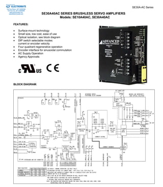
  • 1. SE30A-AC Series SE30A40AC SERIES BRUSHLESS SERVO AMPLIFIERS Models: SE10A40AC, SE30A40AC Sold & Serviced By: ELECTROMATE Toll Free Phone (877) SERVO98 Toll Free Fax (877) SERV099 www.electromate.com sales@electromate.com FEATURES: • Surface-mount technology • Small size, low cost, ease of use • Optical isolation, see block diagram • DIP switch selectable modes: current or encoder velocity • Four quadrant regenerative operation • Encoder interface for sinusoidal commutation • AC Supply Operation • Agency Approvals: BLOCK DIAGRAM:
  • 2. Sold & Serviced By: ELECTROMATE SE30A-AC Series Toll Free Phone (877) SERVO98 Toll Free Fax (877) SERV099 DESCRIPTION: The SE30A40AC Series PWM servo amplifiers are designed to drive brushless motors with 3 phase sine wave current. An on board digital controller generates the 3 phase sine wave signals from an optical "incremental encoder". Although encoders are used for the sinusoidal commutation, Hall sensors are required for the start up routine. This model is fully protected against over-voltage, under-voltage, over-current, over-heating and short-circuits. This model interfaces with digital controllers or can be used as a stand-alone drive. The SE30A40AC series requires a single or three-phase AC power supply. A red/green LED and two digital outputs indicate operating status. Loop gain, current limit, input gain and offset can be adjusted using 14-turn potentiometers. The offset adjusting potentiometer can also be used as an on-board input signal for testing purposes when SW1 (DIP switch) is ON. SPECIFICATIONS: All SE10A40AC and SE30A40AC specifications are respectively identical to the SE10A40 and SE30A40 specifications (see SE30A40 series data sheets) except for: www.electromate.com sales@electromate.com D-58 MODEL POWER STAGE SPECIFICATIONS SE10A40AC* SE30A40AC AC SUPPLY VOLTAGE 45-270 VAC, 1 or 3 phase, 50-60 Hz CONTINUOUS DC CURRENT AVAILABLE FROM INTERNAL SUPPLY ** 30 A for three phase AC input 15 A for single phase AC input PEAK DC CURRENT AVAILABLE FROM INTERNAL SUPPLY (MAXIMUM 2 SECONDS) ** 60 A for three phase AC input 30 A for single phase AC input INTERNAL SHUNT RESISTOR 30 Ω @ 50 W SHUNT SWITCH-ON VOLTAGE ** 390 V BUS CAPACITANCE 1980 μF SHUNT FUSE (d=.25 inches, L=1.25 inches) 3 A Motor Delay rated @ 250 VAC AC LINE FUSES (d=.25 inches, L=1.25 inches) 15 A slow blow rated @ 250 VAC MECHANICAL SPECIFICATIONS AC CONNECTOR: C1 Screw terminals DC OUT AND EXTERNAL SHUNT CONNECTOR: C2* Screw terminals MOTOR CONNECTOR: P3 Screw terminals SIGNAL CONNECTORS: P1, P2 AMP 748390-6, AMP 748481-6 P1 is a 26 pin high density female D-sub connector and P2 is a 15 pin high density female D-sub connector. SIZE 8.00 x 6.52 x 4.06 inches 203.2 x 165.7 x 103.1 mm WEIGHT 4.94 Lb. 2.23 Kg * The internal bus voltage is available on C2 to power DC supply units. ** If the shunt regulator is disabled the shut down voltage is 420 VDC.
  • 3. SE30A-AC Series Sold & Serviced By: ELECTROMATE Toll Free Phone (877) SERVO98 Toll Free Fax (877) SERV099 www.electromate.com sales@electromate.com These amplifiers contain a rectifier bridge and filter capacitors to generate the DC bus internally from the AC input power. The DC bus voltage is 1.4 times AC voltage (RMS), e.g. 310 VDC from 220 VAC. During braking much of the stored mechanical energy is fed back into the power supply and charges the bus capacitor to a higher voltage. If this voltage reaches the amplifier’s over-voltage shutdown point, output current and braking will cease. To ensure smooth braking of large inertial loads, a built-in “shunt regulator” is provided in the SE30A40AC. The shunt regulator will switch on the internal power resistor when the bus voltage reaches 390 VDC. This allows the bus capacitor to discharge and thus lower the bus voltage. During regeneration, the regeneration LED will blink (solid green is non-regeneration mode). An external shunt resistor can be added in parallel to the internal resistor (between C2-3 and C2-4). Recommended value is 20 ohms with a minimum 100 W rating. Removing the jumper between C2-4 and C2-5 will disable the internal shunt resistor. If the shunt regulator becomes inoperative the over voltage protection on the amplifier will disable the drive if the regeneration energy causes the bus voltage to exceed 425 VDC. D-59 ORDERING INFORMATION: Models: SE10A40AC and SE30A40ACX *Divide by 4 option Models: SE10A40AC-4 and SE30A40ACX-4 *Divide by 8 option Models: SE10A40AC-8 and SE30A40ACX-8 *Divide by 16 option Models: SE10A40AC-16 and SE30A40ACX-16 *For use with high-resolution encoders, contact the factory to determine which option is best for your application X indicates current revision letter. MATING CONNECTORS: Manufacturer: AMP (Tel: 1-800-522-6752) Part numbers: 15 Pin plug 748364-1 26 Pin plug 748365-1 Pins 748333-2 Shell Kit (plastic with metal coating) 15 Pin 748677-1 26 Pin 748677-2 TYPICAL SYSTEM WIRING: See section “G”. MOUNTING DIMENSIONS: See page F-14.
  • 4. SE30A Series D-45 SE30A SERIES BRUSHLESS SERVO AMPLIFIERS Models: SE10A8, SE10A20, SE10A40, SE30A8, SE30A20, SE30A40 Sold & Serviced By: ELECTROMATE Toll Free Phone (877) SERVO98 Toll Free Fax (877) SERV099 www.electromate.com sales@electromate.com FEATURES: • Surface-mount technology • Small size, low cost, ease of use • Optical isolation, see block diagram • DIP switch selectable modes: current, encoder velocity, external velocity, tachometer • Four quadrant regenerative operation • Encoder interface for sinusoidal commutation • Agency Approvals: BLOCK DIAGRAM: ADVANCED MOTION CONTROLS 3805 Calle Tecate, Camarillo, CA 93012 Tel: (805) 389-1935, Fax: (805) 389-1165
  • 5. Sold & Serviced By: ELECTROMATE SE30A Series Toll Free Phone (877) SERVO98 Toll Free Fax (877) SERV099 DESCRIPTION: The SE30A20 Series PWM servo amplifiers are designed to drive brushless motors with 3 phase sine wave current. An on board digital controller generates the 3 phase sine wave signals from an optical "incremental encoder". Although encoders are used for the sinusoidal commutation, Hall sensors are required for the start up routine. This model is fully protected against over-voltage, under-voltage, over-current, over-heating and short-circuits. This model interfaces with digital controllers or can be used as a stand-alone drive. The SE30A20 series amplifiers require only a single unregulated DC power supply. A red/green LED and two digital outputs indicate operating status. Loop gain, current limit, input gain and offset can be adjusted using 14-turn potentiometers. The offset adjusting potentiometer can also be used as an on-board input signal for testing purposes when SW1 (DIP switch) is ON. SPECIFICATIONS: www.electromate.com sales@electromate.com D-46 MODEL POWER STAGE SPECIFICATIONS SE10A8* SE10A20* SE10A40 SE30A8* SE30A20* SE30A40 DC SUPPLY VOLTAGE 20-80 V 60-190 V 60-400 V 20-80 V 60-190 V 60-400 V PEAK CURRENT (2 sec. Max., internally limited) ±10 A (7.1 Arms) ±10 A (7.1 Arms) ±10 A (7.1 Arms) ±30 A (21.2 Arms) ±30 A (21.2 Arms) ±30 A (21.2 Arms) MAXIMUM CONTINUOUS CURRENT (internally limited) ±5 A (3.5 Arms) ±5 A (3.5 Arms) ±5 A (3.5 Arms) ±15 A (10.6 Arms) ±15 A (10.6 Arms) ±15 A (10.6 Arms) MINIMUM LOAD INDUCTANCE * 200 μH 250 μH 600 μH 200 μH 250 μH 600 μH SWITCHING FREQUENCY 20 kHz nominal HEATSINK (BASE) TEMPERATURE RANGE 0o to +65o C, disables if > 65o C POWER DISSIPATION AT CONT. CURRENT 20 W 50 W 100 W 60 W 145 W 300 W OVER-VOLTAGE SHUT-DOWN (self reset) 84 V 195 V 425 V 84 V 195 V 425 V BANDWIDTH (load dependent) 2.5 kHz MECHANICAL SPECIFICATIONS POWER CONNECTOR: P3 Screw terminals SIGNAL CONNECTORS: P1, P2 P1 is a 26 pin high density female D-sub connector and P2 is a 15 pin high density female D-sub connector. SIZE 8.00 x 5.62 x 1.60 inches 203.2 x 142.9 x 40.7 mm WEIGHT 2.12 lb. 0.99 Kg * Low inductance motors require external inductors.
  • 6. SE30A Series Sold & Serviced By: ELECTROMATE Toll Free Phone (877) SERVO98 Toll Free Fax (877) SERV099 PIN FUNCTIONS: CONNECTOR PIN NAME DESCRIPTION / NOTES I/O 1 +10V @ 3 mA For customer use O 2 SIGNAL GND Reference ground SGND 3 -10V @ 3 mA For customer use O 4 +REF 5 -REF D-47 Differential reference input, maximum ±15V, 20K input resistance I 6 Velocity Input Single ended reference input, external velocity signal, maximum ±15V, 10K input resistance I 7 Velocity Monitor SW2-3=OFF; 1 V = 25 kHz Encoder frequency, maximum 250 KHz SW2-3=ON; 1 V = 175 kHz Encoder frequency, maximum 1.75 MHz O 8 Current Monitor This signal is proportional to the RMS current in the motor leads. Models SE10A: 1V = 1.33 A Models SE30A: 1V = 4 A O 9 Current Reference This is the command signal to the internal current-loop. The maximum peak current rating of the amplifier always equals 7.25 V at this pin. Models SE10A: SW1-3=ON, 7.25V=10A; SW1-3=OFF, 7.25V=5A. Models SE30A: SW1-3=ON, 7.25V=30A; SW1-3=OFF, 7.25V=15A. O 10 Phase TTL level output: Output is low when commutating in trapezoidal mode and will be high when the amplifier is commutating sinusoidally. O 11 Inhibit/Enable This TTL level input signal turns off all power devices of the “H” bridge when pulled to ground with SW1-6=ON. If SW1-6 = OFF pulling this pin to ground will enable the amplifier. This inhibit will cause a fault condition and a red LED. For inverted inhibit inputs, see section "G". I 12 +Inhibit/Enable I 13 -Inhibit/Enable If SW1-6=ON, pull P1-12 to ground to inhibit (+) amplifier output and P1- 13 to inhibit (-) amplifier output. If SW1-6=OFF, pull P1-12 to ground to enable (+) amplifier output and P1- 13 to enable (-) amplifier output. These inputs will NOT cause a fault condition or a red LED. I 14 Fault (LED red) TTL level output. Becomes high during output short circuit, over-voltage, inhibit, over-temperature and during power-on reset. Fault condition indicated by red LED. O 15 +5V @ 250mA For customer use. Note: the total current on P1-15 and P2-13 combined should not exceed 250 mA. O 16 SIGNAL GND Reference ground SGND 17 Controller Power* Connected to P2-15. For customer use I 18 Controller Line 1* Connected to P2-10. For customer use I 19 Controller Line 2* Connected to P2-11. For customer use I 20 Encoder Channel A+ Encoder Output (from connector P2) O 21 Encoder Channel A-Differential 22 Encoder Channel B+ 23 Encoder Channel B-Differential Encoder Output (from connector P2) O 24 Index+ 25 Index- Differential Encoder Output (from connector P2) O www.electromate.com sales@electromate.com P1 26 Reserved NOTE: All circuits on connectors P1 and P2 are optically isolated fromall circuits on connector P3. * No connection internal to the amplifier. See block diagram.
  • 7. Sold & Serviced By: ELECTROMATE SE30A Series Toll Free Phone (877) SERVO98 Toll Free Fax (877) SERV099 www.electromate.com sales@electromate.com PIN FUNCTIONS: CONNECTOR PIN NAME DESCRIPTION / NOTES I/O D-48 1 HALL 1 2 HALL 2 3 HALL 3 Hall sensor inputs, internal 2K pull-up, logic levels: maximum low level input is 1.5VDC, minimum high level input is 3.5VDC I 4 Encoder Channel A+ 5 Encoder Channel A-Differential Encoder Input I 6 Encoder Channel B+ 7 Encoder Channel B- Differential Encoder Input I 8 Encoder Channel I+ Encoder Input (Not Required) I 9 Encoder Channel I-Differential 10 Controller Line 1* Connected to P1-18. For customer use. O 11 Controller Line 2* Connected to P1-19. For customer use. O 12 Signal GND Reference ground SGND 13 +5V @ 250mA For customer use. Note: the total current on P1-15 and P2-13 combined should not exceed 250 mA. O 14 TACH Tachometer Input, 60 KΩ input resistance, ± 60 V max. I P2 15 Controller power* Connected to P1-17. For customer use. O 1 MOTOR A Motor phase A connection O 2 MOTOR B Motor phase B connection O 3 MOTOR C Motor phase C connection O 4 POWER GND Power ground PGND P3 5 HIGH VOLTAGE DC power input I NOTE: All circuits on connectors P1 and P2 are optically isolated from all circuits on connector P3. * No connection internal to the amplifier. See block diagram.
  • 8. SE30A Series D-49 Sold & Serviced By: SWITCH FUNCTIONS: BANK 1 SETTING SWITCH FUNCTION DESCRIPTION ON OFF 1-1 Test / Offset controls the sensitivity of the "offset" pot. This is used as an on-board reference signal in test mode. Test Offset 1-2 Current loop gain* Decrease Increase 1-3 Current scaling. When OFF, this increases the sensitivity of the current sense thus reducing both peak and continuous current limit by 50%. 100% 50% 1-4 Continuous current reduction Continuous / peak current limit ratio is 50% Continuous / peak current limit ratio is 25% 1-5 60/120 degree commutation phasing 120 degree phasing 60 degree phasing 1-6 INHIBIT/ENABLE P1-11, 12, 13 : INHIBIT P1-11, 12, 13 : ENABLE * See item “6.3 Current Loop Adjustments” in section G for more information. Units are shipped set for ½ current output via SW1-3=off and in the disabled state via SW1-6=off. BANK 2 SETTING SWITCH FUNCTION DESCRIPTION ON OFF 2-1 Encoder Velocity feedback. This connects the internally generated velocity signal from the encoder. Encoder velocity feedback enabled. Encoder velocity feedback disabled. 2-2 Reserved Must be OFF. 2-3 Velocity Monitor Scaling 1V=175 KHz 1V=25 KHz 2-4 Velocity Feedback Polarity Toggles the polarity of the encoder velocity feedback. 2-5 Loop integrator. This capacitor normally ensures "error-free" operation in velocity mode by reducing the error signal (output of summing amplifier) to zero. Disables velocity / voltage loop integrator capacitor Enables velocity / voltage loop integrator capacitor 2-6 Integrator capacitor. This adjusts the value of the integrator capacitor in the velocity mode. Increase Decrease ELECTROMATE Toll Free Phone (877) SERVO98 Toll Free Fax (877) SERV099 www.electromate.com sales@electromate.com
  • 9. Sold & Serviced By: ELECTROMATE SE30A Series Toll Free Phone (877) SERVO98 Toll Free Fax (877) SERV099 POTENTIOMETER FUNCTIONS: www.electromate.com sales@electromate.com POTENTIOMETER DESCRIPTION TURNING CW D-50 Pot 1 This potentiometer is the loop gain adjustment in the velocity mode. Turn this pot fully CCW in current mode. Increases loop gain Pot 2 Current limit. This potentiometer adjusts both the continuous and peak current limit while maintaining a selected ratio. Increases current limit Pot 3 Reference in gain. This potentiometer adjusts the ratio between input signal and output variables (current, velocity). Increases reference input gain Pot 4 Test / Offset. Used to adjust any imbalance in the input signal or in the amplifier. When SW1-1 (DIP switch) is ON, the sensitivity of this pot is greatly increased allowing it to be used as an on-board signal source for testing purposes. N/A TEST POINTS FOR POTENTIOMETERS: See section "G". OPERATING MODE SELECTION: FEEDBACK MODE The following operating modes can be selected by setting the DIP switches according to the following chart: • Current mode • Encoder velocity mode • External velocity mode • Tachometer mode MODE SW1-1 SW1-2 SW1-3 SW1-4 SW1-5 SW1-6 SW2-1 SW2-2 SW2-3 SW2-4 SW2-5 SW2-6 Current Mode X X X X X X OFF OFF OFF X ON OFF Encoder Velocity Mode X X X X X X ON OFF OFF X OFF X External velocity mode X X X X X X OFF OFF OFF X OFF X Tachometer mode X X X X X X OFF OFF OFF X OFF X X does not affect mode. 120°/60° PHASE SENSOR START UP: In sinusoidal mode, the motor will be commutated using the Hall sensors for a minimum of one torque cycle and a maximum of two torque cycles to synchronize the motor phases with the encoder. Once the phases are synchronized the amplifier will commutate the motor sinusoidally. The In-phase indicator will indicate when the amplifier is commutating sinusoidally. If the encoder signals are lost the amplifier will commutate the motor using the Hall sensors and then attempt to re-synchronize the motor phase with the encoder. The In-phase output will deactivate when the amplifier is commutating using Hall sensors.
  • 10. SE30A Series Sold & Serviced By: ELECTROMATE Toll Free Phone (877) SERVO98 Toll Free Fax (877) SERV099 APPLICATION NOTE: For proper operation, P1-6, and P2-14 must be connected to the signal ground if they are not being used. D-51 www.electromate.com sales@electromate.com SET-UP: See section "G" for engineering and installation notes. CURRENT LIMIT ADJUSTMENTS: These amplifiers feature separate peak and continuous current limit adjustments. The current limit adjustment Pot 2 adjusts both peak and continuous current limit at the same time. It has 12 active turns and one inactive turn at each end. This pot is approximately linear. Thus, to adjust the current limit turn the potentiometer counter-clockwise to zero, then turn clockwise to the appropriate value. In many applications it is sufficient to use only the DIP-switches for current limit adjustments. SW1-3 reduces both peak and continuous current limit by 50% when OFF. SW1-4 reduces only the continuous current limit by 50% when OFF: SW1-4 CONTINUOUS / PEAK CURRENT LIMIT RATIO ON 50% OFF 25% P1-9 is the input to the internal current amplifier power stage. Since the output current is proportional to P1-9, the adjusted current limit can easily be observed at this pin without connecting the motor. Note that a command signal must be applied to the reference inputs to obtain a reading on P1-9. The maximum peak current value equals 7.25 V at this pin and the maximum continuous current value equals 3.63 V at this pin. If SW1-3=ON, peak rated amplifier current = 7.25 V. If SW1-3=OFF, ½ peak rated amplifier current =7.25 V. Example: using the SE30A20 with SW1- 3=ON, 30A=7.25V and with SW1-3=OFF, 15A=7.25V. The actual output current can be monitored at pin P1-8. TYPICAL SYSTEM WIRING: See section "G". MATING CONNECTORS: Manufacturer: AMP (Tel: 1-800-522-6752) Part numbers: 15 Pin plug 748364-1 26 Pin plug 748365-1 Pins 748333-2 Shell Kit (plastic with metal coating) 15 Pin 748677-1 26 Pin 748677-2
  • 11. Sold & Serviced By: ELECTROMATE SE30A Series Toll Free Phone (877) SERVO98 Toll Free Fax (877) SERV099 ORDERING INFORMATION: Models: SE10A8X, SE10A20X, SE10A40X, SE30A8X, SE30A20X and SE30A40X *Divide by 4 option Models: SE10A8X-4, SE10A20X-4, SE10A40X-4, SE30A8X-4, SE30A20X-4 and SE30A40X-4 *Divide by 8 option Models: SE10A8X-8, SE10A20X-8, SE10A40X-8, SE30A8X-8, SE30A20X-8 and SE30A40X-8 *Divide by 16 option Models: SE10A8X-16, SE10A20X-16, SE10A40X-16, SE30A8X-16, SE30A20X-16 and SE30A40X-16 *For use with high-resolution encoders, contact the factory to determine which option is best for your application X indicates the current revision letter. MOUNTING DIMENSIONS: See page F-13. www.electromate.com sales@electromate.com D-52