

Recomendados
Recomendados
Más contenido relacionado
La actualidad más candente
La actualidad más candente (20)
Similar a Inertia dynamics pcbc825f_specsheet
Similar a Inertia dynamics pcbc825f_specsheet (17)
Más de Electromate
Más de Electromate (20)
Último
Último (20)
Inertia dynamics pcbc825f_specsheet
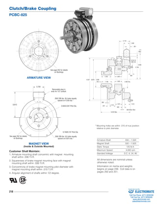
- 1. Clutch/Brake Coupling PCBC-825 218 5/16-18 UNC-3A .562 1.437 * Mounting holes are within .010 of true position relative to pilot diameter. Armature Shaft .500 – 1.500 Magnet Shaft .500 – 1.625 Static Torque 125 lb.ft. Maximum Speed 4,000 rpm Standard Voltage D.C. 6, 24, 90 See page 252 for details Removable plug in ends for 1/2" conduit. Customer Shall Maintain: 1. Armature mounting shaft concentric with magnet mounting shaft within .006 T.I.R. 2. Squareness of brake magnet mounting face with magnet mounting shaft within .006 T.I.R. 3. Concentricity of brake magnet mounting pilot diameter with magnet mounting shaft within .010 T.I.R. 4. Angular alignment of shafts within 1/2 degree. .062 .531 1.312 9.437 8.625 2.500 1.312 .562 2.562 Dia. 5.656 1.546 .171 Max. .921 5.750 .093 When New 2.718 1.250 1.500 .156 1.765 1.593 6.250 Max. ARMATURE VIEW on Bushings. MAGNET VIEW (Inside & Outside Mounted) .358/.338 dia. (6) holes equally spaced on 4.250 dia.* 3.503/3.501 Pilot Dia. 9.749/9.747 Pilot Dia. .358/.338 dia. (4) holes equally spaced on 8.875 dia.* 6.812 See page 252 for details on Bushings. 3.750 All dimensions are nominal unless otherwise noted. Information on inertia and weights begins on page 239. Coil data is on pages 250 and 251. Sold & Serviced By: ELECTROMATE Toll Free Phone (877) SERVO98 Toll Free Fax (877) SERV099 www.electromate.com sales@electromate.com
- 2. Clutch/Brake Coupling PCBC-825 219 Drawing I-25570 How to Order: 1. Specify Bore Size for Items 1 and 9. 2. Specify Voltage for Items 6 and 13. 3. Specify left hand or right hand hub for Item 7. Bushing enters from magnet side for L.H. hub and from hub side for R.H. 4. Specify Inside Mounted for Items 12A and 13A or Outside Mounted for Items 12B and 13B. 5. See Controls Section. Example: PCBC-825 Clutch Brake Coupling per I-25570 - 90 Volt, Inside Mounted, Left Hand hub, 1" Bore, ( Items 1 and 9) These units meet the standards of UL508 and are listed under guide card #NMTR2, file #59164. These units are CSA certified under file #LR11543. 1 2 3 4-1 4 5 4-2 4-3 4-5 6 6-1 9 4-4 7-1 7-2 7 (Shipped Assembled) 11 8-1 8 10 12A 13A 13A-1 14 14 13B 13B-1 12B Item Description Part Number Qty. 1 Bushing* - 1/2" to 1-1/2" Bore 180-0002 to 180-0018 1 2 Retainer Ring 748-0006 1 3 Splined Hub 540-0057 1 4 Armature & Splined Adapter 5321-111-001 1 4-1 Locknut 661-0004 3 4-2 Armature 5321-111-022 1 4-3 Splined Adapter 104-0008 1 4-4 Autogap Accessory 5321-101-006 1 4-5 Screw 797-0272 3 5 Mounting Accessory 5321-101-001 1 6 Magnet 1 6 Volt 5301-631-002 24 Volt 5301-631-004 90 Volt 5301-631-005 6-1 Terminal Accessory 5311-101-001 1 7 Magnet Hub 1 Left Hand (shown) 5301-541-001 Right Hand 5301-541-002 7-1 Collector Ring 5301-749-001 1 7-2 Collector Ring Accessory 5301-101-002 1 8 Brushholder 5300-178-001 1 8-1 Brush 176-0001 4 9 Bushing* - 1/2" to 1-5/8" Bore 180-0131 to 180-0149 1 10 Armature 5301-111-018 1 11 Autogap Accessory 5201-101-008 3 12A Mounting Accessory - I.M. 5321-101-001 1 12B Mounting Accessory - O.M. 5321-101-002 1 Item Description Part Number Qty. 13A Magnet - Inside Mounted 1 6 Volt 5311-631-002 24 Volt 5311-631-003 90 Volt 5311-631-004 13A-1 Terminal Accessory 5311-101-001 1 13B Magnet - Outside Mounted 1 6 Volt 5311-631-007 24 Volt 5311-631-009 90 Volt 5311-631-008 13B-1 Terminal Accessory 5311-101-001 1 14 Conduit Box 5200-101-011 1 *See page 252 for specific part numbers. Refer to Service Manual P-205. Sold & Serviced By: ELECTROMATE Toll Free Phone (877) SERVO98 Toll Free Fax (877) SERV099 www.electromate.com sales@electromate.com