
Recomendados
Más contenido relacionado
La actualidad más candente
La actualidad más candente (20)
Destacado
Destacado (15)
Similar a Solar Chimneys
Similar a Solar Chimneys (20)
Más de Fayina19z
Más de Fayina19z (20)
Último
Último (20)
Solar Chimneys
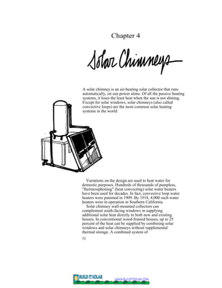
- 1. Chapter 4 A solar chimney is an air-heating solar collector that runs automatically, on sun power alone. Of all the passive heating systems, it loses the least heat when the sun is not shining. Except for solar windows, solar chimneys (also called convective loops) are the most common solar heating systems in the world. Variations on the design are used to heat water for domestic purposes. Hundreds of thousands of pumpless, "thermosiphoning" (heat convecting) solar water heaters have been used for decades. In fact, convective loop water heaters were patented in 1909. By 1918, 4,000 such water heaters were in operation in Southern California. Solar chimney wall-mounted collectors can complement south-facing windows in supplying additional solar heat directly to both new and existing houses. In conventional wood-framed houses, up to 25 percent of the heat can be supplied by combining solar windows and solar chimneys without supplemental thermal storage. A combined system of 52
- 2. Solar Chimneys 53 roughly 200 square feet can achieve the 25 percent figure for a well-insulated 1500-square-foot house in a cold climate. Half as much area is needed in a mild climate. Basic System Design A solar chimney wall collector is similar to a flat-plate collector used for active systems. A layer or two of glass or plastic covers a black absorber. Air may flow in a channel either in front of or behind the absorber, depending on the design. The air may also flow through the absorber if it is perforated. The collector is backed by insulation. In the figure on the next page, the collector is mounted on, or made a part of, the insulated wall. Openings at the bottom and top of the wall permit cooler air from the house to enter the hot collector at the base of the wall, to rise as the sun heats it, and to vent back into the building near the ceiling. The slow-moving collector air must be able to come in contact with as much of the absorber's surface area as possible without being slowed down too much. In fact, the amount of heat transferred from the absorber to the flowing air is in direct proportion to the heat-transfer capabilities of the absorber and the speed of the air flow by or through it. Up to six layers of expanded metal lath is used in some absorbers. In these, the air rises in front of the lath, passes through it, and leaves the collector through a channel behind the lath. Flat or corrugated metal is also used, but it does not transfer heat as well. However, the air flow channel in this case need not be as deep. The metal should
- 4. Solar Chimneys 55 be placed in the center of the channel, if possible, so that air flows on both sides. This is more difficult to do and requires two glazing layers instead of one. Construct the collectors carefully and insulate them well} particularly the upper areas that are likely to be hottest. Avoid insulations or glazings that will melt. If the collector’s flow should be blocked for some reason on a sunny day, its temperature can reach over 300°F. Wood construction is usually satisfactory, but be sure to provide for wood shrinkage and for the expansion and contraction of materials as their temperatures fluctuates. Systems with Heat Storage Collectors that are large enough to supply more than 25 percent of the desired heat require heat storage. The storage in an air system is usually a large bin of rocks. It must be designed to maximize heat transfer from the air stream to the rocks without noticeably slowing the air flow. Rocks with small diameters (3 to 6 inches) have large amounts of surface area for absorbing heat} and yet allow passages for air flow. The rocks should be roughly the same size (that is} don}t mix 1 inch with 4 inch) or most of the airways will be clogged. Storage should contain at least 200 pounds of rock (1 1/2 cubic feet) per square foot of collector. As shown in the diagram} storage should be located
- 5. 56 Passive Solar Heating The cross-sectional area of the rock bed above the collector but below the house. This permits receiving air from the collector should range from one-half to three-quarters the surface solar heated air to rise into the house and cooler air to area of the collector. The warm air from the settle in the collector. collector should flow down through the rocks, and the supply air from storage to the house should flow in the reverse direction. Optimum rock size depends on rock bed depth. Steve Air Flow Baer recommends gravel as small as 1 inch for rockbeds 2 feet deep and up to 6 inches for Designing a convective air loop system is a somewhat tricky and depths of 4 feet. * For best heat transfer in difficult task. If you aren't very respectful of the will of the air, the active systems, bed depths are normally at system won't work. least 20 rock diameters. That is, if the rock is 4 inches in diameter, the bed should be at least Steve Baer 6 1/2 feet deep in order to remove most of the As with active collectors, the slower the air flow, the hotter heat from the air before it returns to the collector. This should be considered a the absorber and the greater the heat loss through the glazing. maximum depth for convective loop rockbeds. This results in a lower collector efficiency. Good air flow * See Sunspots by Steve Baer, Zomeworks keeps the absorber cool and transports the maximum possible Corporation, Albuquerque, NM. amount of heat into the house flow.
- 6. Solar Chimneys 57 channels should be as large as possible, and bends and turns in the ducts should be minimized to prevent restriction of air flow. Conventional air heating collectors use fans and have air channels only 1 ½ to 1 inch deep. Without fans, air channels in convective loop collectors range from 2 to 6 inches deep. Convective flow of air is created by a difference in temperature between the two sides of the convective loops, for example, between the average temperature in the collector and the average temperature of the adjacent room. It is also affected by the height of the loop. The best air flow occurs when the collector is hottest, the room is coolest, and the height of the collector is as tall as possible. The vertical distance to the top of the collector from the ground (this is not necessarily the collector length, since the collector is tilted) should be at least 6 feet to obtain the necessary effect. It should be tilted at a pitch of not less than a 45° angle to the ground, to allow for a good angle of reception to the sun and for the air to flow upward. Reverse air convection In an improperly designed system, reverse air convection can occur when the collector is cool. A cool collector can draw heat from the house or from storage. Up to 20 percent of the heat gained during a sunny day can be lost through this process by the following day. There are three primary methods of automatically preventing reverse convection. One is to build the collector in a location below the heat storage and below the house. A second is to install backdraft dampers that automatically close when air flows in the wrong direction. One such damper is made of lightweight, thin plastic film. A lightweight "frisket" paper used in the photography industry has also been used successfully. Warm air flow gently pushes it open. Reverse cool air flow causes the plastic to fall back against the screened opening, stopping air flow. Ideally, both top and bottom vents should be equipped with such dampers. This is discussed in more detail in two excellent magazine articles by W. Scott Morris (Solar Age, September 1978 and January 1979, Harrisville, N.H. 034501.
- 7. 58 Passive Solar Heating
- 8. Solar Chimneys 59 The third method of reducing reverse convection is to place the intake vent slightly lower than the outlet vent near the top of the wall. The back of the absorber is insulated and centered Collector Area between the glazing and the wall. Inlet cool air from the Only a small collector area is needed ceiling drops into the channel behind the absorber. The solar to heat a house in the spring and fall heated air rises in the front channel, drawing cooler air in when the heating demand is low. behind it. The warmed air enters the room at the top of the Additional collector area provides heat wall. When the Sun is not shining, the air in both channels over a fewer number of months, only cools and settles to the bottom of the "U -tube." Only minor during the middle of the heating reverse convection occurs. Because of the longer air-travel season. Therefore, each additional distances involved, the U-tube collector will not be as square foot of collector supplies efficient, aerodynamically, as the straight convective loop. It slightly less energy to the house than will also be more expensive to build. the previous square foot. The useful amount of heat supplied from a solar collector ranges from 30, 000 to 120,000 Btus per square foot per winter. The high numbers in this range are for undersized systems in cold, sunny climates. The low numbers are for oversized systems or Costs and Performance for very cloudy climates. In cold climates of average sunshine such as Materials costs of solar chimney collectors can be as little as a Boston, Massachusetts, 80,000 Btus per square foot per heating season is few dollars per square foot. Materials are usually available typical, when the solar system is sized locally. Contractor-built collectors can cost $7 to $15 per to contribute 50 percent of the heat. square foot. Operating costs are nonexistent, and maintenance The output of the collectors drops to costs should be very low. 50,000 Btus when sized to provide 65 Performance depends largely on delicate, natural to 70 percent of the heat. (For convection currents in the system. Therefore, proper design, comparison, roughly 80,000 Btus are materials, and construction are important. In a well-built obtainable from a gallon of oil.) collector, air flow can be low to nonexistent at times of little or no Sun, but will increase rapidly during sunny periods. Average collection efficiency is similar to that of low temperature, flat-plate collectors used in standard active system designs.