Methanol Synthesis Loop Troubleshooting Guide
•
10 recomendaciones•9,988 vistas

Methanol Synthesis Loop Troubleshooting INTRODUCTION TROUBLESHOOTING CONVERTER PROBLEMS OPERATING PROBLEMS CATALYST PROBLEMS TROUBLESHOOTING Common Problems APPENDIX Design Case Study #6752014GB/H

Recomendados
Recomendados
Más contenido relacionado
La actualidad más candente
La actualidad más candente (20)
Destacado
Similar a Methanol Synthesis Loop Troubleshooting Guide
Similar a Methanol Synthesis Loop Troubleshooting Guide (20)
Más de Gerard B. Hawkins
Más de Gerard B. Hawkins (20)
Último
Último (20)
Methanol Synthesis Loop Troubleshooting Guide
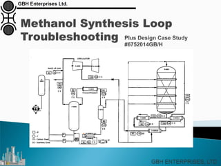
- 1. Plus Design Case Study #6752014GB/H
- 2. CONTENTS INTRODUCTION TROUBLESHOOTING CONVERTER PROBLEMS OPERATING PROBLEMS CATALYST PROBLEMS TROUBLESHOOTING Common Problems APPENDIX Design Case Study #6752014GB/H
- 3. Introduction This presentation details some common problems that can occur in a methanol synthesis loop. Examples of Converter Problems Example Operating Problems Example Catalyst Problems Some typical examples include, but are not limited to, Rapid catalyst deactivation due to poisoning, Failure of vessel components, High by-products levels, Temperature excursions.
- 5. Quench Converter: “Cold Core” Problem The term “Cold Core” usually refers to a problem observed with the old Quench-style converter. This traditional converter design (as shown on the right), in which the synthesis reaction is quenched by the addition of shots of cold gas between catalyst beds. The quench is added to the gas reacting within the converter by means of banks of transverse sparge pipes which have a regular pattern of holes. These spargers are in void space within a horizontal mesh covered structure whose vertical shape is that of a lozenge
- 6. Quench Converter: “Cold Core” Problem However, there have been problems due to the phenomenon known as 'Cold Cores'. This originates from portions of the catalyst that have a high voidage and therefore a high gas flow whilst other portions had a low voidage and therefore a low flow. This causes a zone that is hot (due to low flow) and a zone that is cold (due to high flow). When shot is added to these hot and cold zones at an equal rate through out the converter this causes a wide variation in the temperature inlet the next bed. As there is essentially no cross mixing within the converter, the effect passes down through the whole converter leading to severe operational difficulties.
- 7. Quench Converter: Dust in Lozenges Some quench converters suffered from blockage of the lozenge mesh, see figure below which illustrates the design of the lozenge. This can lead to problems of gas distribution between the hot bed exit gas and cool shot gas. This causes some problems in terms of operation since such blockages prevented good mixing between the effluent from the previous bed and the shot gas.
- 8. (TCC) Tube Cooled Converter Issue A similar problem was also evident in early TCC (Tube Cooled Converters), due to the spread of temperatures exit the tubes / inlet the catalyst bed. The problem here was that if the bed side temperature was low due to high gas flowrates, then there would be a localized reduction in the total heat transferred. This causes a smaller than expected temperature rise up the tubes, thereby reducing the inlet bed (turn) temperature. This causes the catalyst local to that tube to have a low inlet temperature and therefore the bed temperatures will be low.
- 9. (TCC) Tube Cooled Converter Issue This problem was resolved through design of a gas collection / mixing device as shown to the right. This then caused low tubeside temperatures and a feedback loop was developed. The same effect occurred for zones of low flow which led to high temperatures etc.
- 10. (TCC) Tube Cooled Converter Design Issue Generic Design Tubesheet installed in the bottom of the converter Modified Design
- 11. (TCC) Tube Cooled Converter: Exit Collector During the discharge of an Asia Pacific Methanol Plant converter, it was found that the mesh that should have been installed over the exit collected had never been installed. The collector consists (as illustrated to the right) of a truncated cone which has 1 cm wide holes in it side to allow for gas flow out of the converter. During the loading and normal operation, this cone was surrounded by inert balls and therefore there was no catalyst ingress into the cone and downstream outlet pipe.
- 12. (TCC) Tube Cooled Converter: Exit Collector To rectify this situation, the outlet pipe had to be cut and the catalyst emptied out; this spool piece has been fitted with flanges. Due to the problems associated with the Manways (only 10” diameter), it has been impossible to place a mesh over the outlet collector and therefore at every catalyst discharge the spool piece will have to be removed.
- 13. OPERATING PROBLEMS E1113E1112 E1110 V1107 Shot Gas Converter Inlet Gas 180 °C 0 0 0 0 Shot Flows kNm3/hr From C1102 210 °C E1111 Loop start Up Heater 100 bar steam TIC 060 HIC 007 240 °C ShutOpen 180 °C 210 190 230 100 220 210 240 150 25 % 50 %
- 14. Operational Problems: Temperature Excursions On a loop trip that affects the circulator, there will be complete loss of circulation around the loop. Since there is still hydrogen and carbon oxides in the converter at high temperature, there will be some methanol synthesis. These reactions cause a volume decrease as outlined below, and there will be a pressure reduction which will in turn lead to further reactants being sucked into the converter. CO2 + 3H2 CH3OH + H2O ΔH = +49 kJ/kmol 4 volumes 2 volumes CO + 2H2 CH3OH ΔH = +90 kJ/kmol 3 volume 1 volume
- 15. Operational Problems: Temperature Excursions At an Americas Methanol plant, during a plant trip, there was a temperature excursion. This plant had a separate circulator and synthesis gas machine, but in this case, the minimum stop on the valve downstream of the saturator water heater (see figure) failed and closed shut.
- 16. Operational Problems: Failure of Mesh on Exit of Quench Converters The outlet collector of the Quench Converter is covered in a mesh to prevent catalyst passing through the collector during discharge. During normal operation, the collector is surrounded by inert balls. However, if the mesh fails, inert balls and catalyst will be passed into the outlet pipe of the reactor. This will lead to very high pressure drop, which will cause the plant to be shut down and then synthesis catalyst to be changed out.
- 17. Operational Problems: Leakage of Balls from ARC Bottom Beds In ARC converters, there is a sealing ring at the bottom of the converter which is aimed at preventing inerts balls and subsequently catalyst passing into the outlet pipe work and then on to downstream equipment. This ring is not welded to the shell (an important feature of the ARC converter which makes it simple to install). Catalyst Support Plates Individual / Separate Catalyst Beds Gas Mixing System
- 18. Operational Problems: Oil Leaks Many circulators use oil on the seals to prevent damage to the shaft of the machine. This oil can and does leak into the synthesis gas and is passed to the converter where it is converted into longer chained alkanes commonly known on methanol plants as waxes.
- 19. Operational Problems: Impingement Corrosion Severe corrosion can result from the high velocity impingement of liquid droplets entrained in a gaseous stream on a metal surface, even though the environment would not be considered corrosive under still conditions. Mild and low alloy steels are among the metals which are particularly susceptible to this form of attack. Problems can often be solved simply by upgrading to a higher alloy. Conditions which could lead to impingement attack occur in those parts of the loop where condensation takes place, or condensate is present.
- 20. Operational Problems: Impingement Corrosion The actions which must be taken to eliminate this problem are: Reduction of gas velocity by increasing of the inlet pressure to the compressor. Adjusting the level within the MUG separator to maximize efficiency. Balancing the heat load in the cooler and condenser prior to the MUG separator.
- 21. Operational Problems: Fouling of Crude Cooler There are two ways of fouling the crude cooler. The first is from wax formation which will foul the tube side. The second is from shell side fouling – normally due to excessively high (50-60°C) return cooling water temperatures leading to the hardness in the cooling water plating out on the outside of the tubes
- 22. Operational Problems: Make Up Gas Compositions There is theoretical evidence that shows that synthesis gases with high CO2 levels can lead to surface oxidation of the methanol synthesis catalyst. This in turn leads to an apparent loss of activity. Comp Mole Frac (Methane) 0.111% Comp Mole Frac (Nitrogen) 0.490% Comp Mole Frac (Hydrogen) 69.028% Comp Mole Frac (CO2) 6.054% Comp Mole Frac (H2O) 0.094% Comp Mole Frac (CO) 24.222%
- 23. Operational Problems: Boiler Feed Water Quality At a small South American methanol plant there was a serious failure of the tubes within their Steam Raising Converter. It was found that the cause was poor boiler feed water quality which lead to stress corrosion cracking of the tube sheet to tube weld.
- 24. Operational Problems: Deposits on the Synthesis Gas Machine and Circulator At a South American methanol plant it was found that the synthesis gas machine capacity was dropping; that is for a fixed power usage, the flowrate through the machine dropped. On inspection, it was found that there was a thick deposit on the blades of the machine. This was analysed and found to be a mixture of iron of nickel. A similar effect was seen on the circulator.
- 25. Operational Problems: Methanol carryover from catchpot Some plants have suffered from liquid carry over from the loop catchpot which can lead to damage to the circulator. This also increases the methanol content of the gas entering the converter, thereby giving a less favorable equilibrium position.
- 27. Low Activity There are a number of reasons for apparent low methanol synthesis catalyst activity including: Poisoning Poor catalyst loading Excessive localized breakage leading to flow mal- distribution. Catalyst Problems
- 28. Catalyst Problems Sintering Sintering is caused by operation at high temperatures which causes the migration of copper between crystallites which causes a loss of copper surface area as illustrated below;
- 29. Catalyst Problems Sintering The activity of the catalyst is proportional to copper surface area, and therefore with time, activity is lost. 0.175 0.275 0.375 0.475 0.575 0 12 24 36 48 Time Months Activity The figure illustrates the typical effect of temperature on activity
- 30. Catalyst Problems Catalyst Breakage Catalyst breakage does occurring during loading and operation, however it is rare that the breakage is so bad that it affects production. There are of course some instances were catalyst breakage does cause a problem.
- 31. Catalyst Problems Byproducts In the synthesis loop there are a number of by-products formed, including, Ethanol and higher alcohol’s such as propanol, butanol etc, Dimethyl ether, Acetone, Ketones including Methyl Ethyl Ketone and Methyl Iso Propanyl Ketone, Methyl Formate, Alkanes from heptane through to C40’s, Methane.
- 32. Catalyst Problems Byproducts TMA TMA or Tri Methyl Amine is a problem in the product methanol since is gives the methanol a fishy smell – methanol has a limit in all product specification that it “shall be free from odour”. TMA is formed by the reaction of ammonia produced in the primary reformer with methanol formed in the loop.
- 33. Methanol Synthesis Catalyst: Poisoning In order to avoid poisoning of the methanol synthesis catalyst, the following limits MUST NOT be exceeded: COMPONENT. LIMIT. Effect Sulfur (as H2S). Such that the maximum accumulated S on the catalyst charge be less than 0.20% of the total mass of catalyst. Poison Chlorine (as HCl). Such that the maximum accumulated Cl on the catalyst charge be less than 0.02% of the total mass of catalyst. Poison Iron. Such that the maximum accumulated Fe on the catalyst charge be less than 0.15% of the total mass of catalyst. Poison and wax formation Carbon (elemental). Absent. ∆P increase Metals e.g. V, K, Na. Absent. Poisons Nickel. Such that the maximum accumulated Ni on the catalyst charge be less than 0.04% of the total mass of catalyst. Poison Ammonia. 10 ppmv in the MUG. TMA formation Ethene. 20 ppmv in the MUG. Ethyne. 5 ppmv in the MUG. Particulate matter. Absent. ∆P increase Hydrogen cyanide. Absent. Poison
- 34. Methanol Synthesis Catalyst: Poisoning Oxygen Oxygen is not normally expected to be present in the synthesis gas. Although oxygen is not a catalyst poison, it is advised that the level does not exceed 0.1% (molar) in the MUG, due to the associated temperature rise and hydrogen consumption. If the oxygen is present at a high enough level, it will lead to bulk oxidation of the catalyst which will be seen as a loss of apparent activity.
- 35. Methanol Synthesis Catalyst: Poisoning Sulfur There have been a number of instances of sulfur poisoning of methanol synthesis catalyst. The mechanism of sulfur poisoning is highlighted
- 36. Methanol Synthesis Catalyst: Poisoning DMS Formation DMS or Dimethyl Sulfide can be formed by the reaction of methanol with hydrogen sulfide. This is normally a problem on methanol plants for the reformer since there is methanol in the purge gas added to the HDS section. The DMS is formed over the HDS catalyst and ZnO but is not removed in the ZnO bed. Therefore is passes straight on to the primary reformer where it causes hot banding.
- 37. Methanol Synthesis Catalyst: Poisoning Ni/Fe Carbonyl Iron and nickel react with carbon monoxide, under certain conditions, to form metal carbonyls. As the reaction is exothermic and involves a reduction of volume in forming Fe(C0)5 or Ni(CO)4, the equilibrium concentration of carbonyl falls with rising temperature and increases rapidly with pressure. Against this, the rate of reaction increases with temperature.
- 38. Methanol Synthesis Catalyst: Poisoning Ni/Fe Carbonyl At 1 bar partial pressure of CO the rate of formation of carbonyl is at a maximum in the range 60-100°C, and decomposition occurs at temperatures over 150° C. At 10 bars partial pressure of CO the rate of formation reaches a maximum at 180-190° C. The maximum rate is also higher, but there should be no significant nickel carbonyl formation above 250° C at low pressures.
- 39. Methanol Synthesis Catalyst: Poisoning Chloride Poisoning Chlorides are a very severe poison for methanol synthesis catalyst, however, it is rare that they are a problem. The figure illustrates the mechanism,
- 40. Methanol Synthesis Catalyst: Poisoning HDS Catalyst of Choice Some methanol plants have experienced methanation of the CO from the hydrogen recycle gas in the HDS vessel. The recommended catalyst to be used is CoMO but some plants have removed the HDS catalyst completely, thereby leaving themselves vulnerable to poisoning by organic sulfur compounds.
- 41. Methanol Synthesis Catalyst: Poisoning Catalyst Discharge Methanol synthesis catalyst in its reduced form is pyrophoric and as such will heat up very rapidly to 600°C or more in the presence of air. There have been numerous instances of such incidents during catalyst discharge. With the advent of discrete catalyst bed converters such as the ARC and CMD converter, a requirement for a safer method of catalyst discharge has developed.
- 42. Methanol Synthesis Loop: Common Problems Problem Effect Solution Low Circulation Rate High Converter Pressure Drop. Check valve position. Check converter DPI meter Mesh damage and catalyst passing into outlet pipe. Catalyst breakage. Low Heat Recovery Fouling of Exchanger. Chemically clean exchanger. Low exit converter temperature. Too little gas through heat recovery exchanger. High Converter Temperature Spreads Cold Core. Raise converter temperature. Change catalyst and ensure good catalyst loading. Instability ARC Low temperatures in converter – large ATE’s exit bed 1. Drop circulation rate. If this fails then raise converter inlet temperature by 0.5°C. Instability TCC Operating below minimum stability point. Raise turn temperature. High Turn Temperature in TCC and loss of Production Too high a recycle rate. Too high a UA. Gag in circulator. Modify converter internals. High Temperature on Trip Methanation. De-pressure on loop trip. Valve failure. Increasing Crude Cooler Exit Temperature Wax deposition. Shell side fouling. Reduce CW flow and raise exit temperature. Chemically clean shellside. Maximise CW flow to keep return CW temperature down. Low Catalyst Activity Catalyst poisoning Temperature excursions. Check for sulphur/chlorides etc. De-pressure loop on trip.
- 43. Conclusions To conclude, a number of potential issues have been highlighted that can affect both the hardware (equipment) and the catalyst in the methanol loop
- 44. APPENDIX: Design Case Study #6752014GB/H
- 45. Design Case Study #6752014GB/H
- 46. Stream Component: Material Balances Table 1
- 47. Stream Component: Material Balances Table 2
- 48. Stream Component: Material Balances Table 3
- 49. Stream Component: Material Balances Table 4