

Recomendados
Más contenido relacionado
La actualidad más candente
La actualidad más candente (20)
Similar a Experiment no
Similar a Experiment no (20)
Último
Último (20)
Experiment no
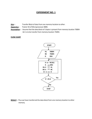
- 1. EXPERIMENT NO. 1 Aim: Transfer Block of data from one memory location to other. Apparatus: - Trainer Kit of Microprocessor 8085. Assumption: - Assume that the data block of 5 bytes is present from memory location 7000H & it is to be transfer from memory location 7500H. FLOW CHART START HL BC D 7000H 7500H 05H A A HL+1 BC+1 D–1 M (HL) (BC) HL BC D IF ZF=0 Yes Z=0 No STOP RESULT: - Thus we have transferred the data block from one memory location to other memory.
- 2. EXPERIMENT NO. 1 Aim: Transfer Block of data from one memory location to other. Apparatus: - Trainer Kit of Microprocessor 8085. Assumption: - Assume that the data block of 5 bytes is present from memory location 7000H & it is to be transfer from memory location 7500H. PROGRAME (MNEMONICS) LXI H,7000H LXI B,7500H MVI D, 05H BACK: MOV A,M STAX B INX H INX B DCR D JNZ BACK(6008H) HLT HEX CODE 21,00,70 01,00,75 16,05 7E 02 23 03 15 C2,08,60 76 MEMORY LOCATION 6000,6001,6002 6003,6004,6005 6006,6007 6008 6009 600A 600B 600C 600D,600E,600F 6010 COMMENT Initialization of memory pointer, I.e. load HL pair with 7000H Initialization of memory pointer, I.e. load BC pair with 7500H Initialization of counter to count 5 bytes to be transfer Move content of memory pointed by HL pair to accumulator Store content of accumulator to memory pointed by BC pair Increment HL pair to point next memory location Increment BC pair to point next memory location Decrement counter D to count NO. of bytes transferred Jump to location specified in the instruction if result is not zero Halt state RESULT: - Thus we have transferred the data block from one memory location to other memory.
- 3. EXPERIMENT NO. 02 Aim: Apparatus: - Find the greatest and smallest No. Trainer Kit of Microprocessor 8085. Part A: - A data block of 10 bytes is present from memory location 7000H write a program to find greatest No. from given block of data and store the result in register B as well as in Memory location 7500H. FLOW CHART START HL C A 7000H 0AH 00H A - M (HL) NO IF CF=1 YES Z=0 A M HL C HL+1 C-1 IF ZF=1 Z=0 A A YES 7500H B STOP NO
- 4. EXPERIMENT NO. 02 Aim: Apparatus: - Find the greatest and smallest No. Trainer Kit of Microprocessor 8085. Part A: - A data block of 10 bytes is present from memory location 7000H write a program to find greatest No. from given block of data and store the result in register B as well as in Memory location 7500H. PROGRAME (MNEMONICS) LXI H,7000H MVI C,0AH MVI A,00H BACK: CMP M JNC 600A MOV A,M INX H DCR C JNZ BACK(6007H) STA 7500H MOV B,A HLT HEX CODE 21,00,70 MEMORY LOCATION 6000,6001,6002 6003,6004 6005,6006 6007 6008,6009,600A 600B 600C 600D 600E,600F,600G 600F.6010.6011 6012 6010 COMMENT Initialization of memory pointer, I.e. load HL pair with 7000H Initialization of counter to count 10 bytes Store lowest No. to compare to find largest No. Compare data of Memory with accumulator to find largest No. Jump to location specified in the instruction if carry is not generated Move data of memory into a accumulator if it is greater Increment HL pair to point next memory location Decrement counter C Jump to location specified in the instruction if result is not zero Store accumulator content i.e. greatest No. into memory 7500H Move data of register A i.e. greatest No. into register B Halt state RESULT: - Thus we have transferred the data block from one memory location to other memory.
- 5. Part B: - A data block of 10 bytes is present from memory location 7000H write a program to find smallest No. from given block of data and store the result in register B as well as in Memory location 7501H. FLOW CHART START HL C A 7000H 0AH FFH A - M (HL) NO IF CF=0 YES Z=0 A M HL C HL+1 C-1 IF ZF=1 NO Z=0 YES A A 7501H D STOP RESULT: - Thus we have found greatest and smallest No. from the given data block.
- 6. Part B: - PROGRAME (MNEMONICS) LXI H,7000H MVI C,0AH MVI A,FFH BACK: CMP M JC 600A MOV A,M INX H DCR C JNZ BACK(6007H) STA 7500H MOV B,A HLT A data block of 10 bytes is present from memory location 7000H write a program to find smallest No. from given block of data and store the result in register B as well as in Memory location 7501H. HEX CODE 21,00,70 MEMORY LOCATION 6000,6001,6002 6003,6004 6005,6006 6007 6008,6009,600A 600B 600C 600D 600E,600F,600G 600F.6010.6011 6012 6010 COMMENT Initialization of memory pointer, I.e. load HL pair with 7000H Initialization of counter to count 10 bytes Store largest No. to compare to find smallest No. Compare data of Memory with accumulator to find largest No. Jump to location specified in the instruction if carry is generated Move data of memory into a accumulator Increment HL pair to point next memory location Decrement counter C Jump to location specified in the instruction if result is not zero Store accumulator content i.e. smallest No. into memory 7500H Move data of register A i.e. smallest No. into register B Halt state RESULT: - Thus we have found greatest and smallest No. from the given data block.
- 7. EXPERIMENT NO. 03 Aim: Apparatus: - Arrange the data block in the ascending & descending order. Trainer Kit of Microprocessor 8085. Part A: - A data block of 10 bytes is present from memory location 7000H write a program to arrange the Nos. in ascending order from memory location 7500H. FLOW CHART START SP HL B A SMALLEST 7FFFH 7500H 0AH FFH PUSH H HL 7000H C 0AH A-M CALL SMALLEST NO (HL) M A (DE) M HL B A FFH A HL+1 B-1 IF CF=0 Z=0 A DE YES M HL YES IF ZF=0 Z=0 NO STOP HL C HL+1 C-1 IF ZF=1 Z=0 YES POP H RET NO
- 8. EXPERIMENT NO. 03 Aim: - Arrange the data block in the ascending & descending order. Apparatus: - Trainer Kit of Microprocessor 8085. Part A: - A data block of 10 bytes is present from memory location 7000H write a program to arrange the No. in ascending order from memory location 7500H. MAIN PROGRAME (MNEMONICS) LXI SP,7FFFH LXI H,7500H MVI B,0AH MVI A,FFH BACK:CALL Smallest(6500H) MOV M,A MVI A,FF STAX D INX H DCR B JNZ BACK(600AH) RST 1 SUB PROGRAME (MNEMONICS) SMALLEST NO. PUSH H LXI H,7000H MVI C,0AH AGAIN:CMP M JC SKIP(650D) MOV A,M HEX CODE 31.FF,7F 21,00,75 06.0A 3E,FF CD,00.65 77 3E,FF 12 23 4E C2, 0A,60 CF HEX CODE E5 21,00,70 0E.0A BE DA,0D,65 7E MEMORY LOCATION 6000,6001,6002 6003,6004,6005 6006,6007 6008,6009 600A,600B,600C 600D, 600E,600F 6010 6011 6012 6013,6014,6015 6016 MEMORY LOCATION 6500 6501,6502,6503 6504,6505 6506 6507,6508,6509 650A COMMENT Initialization of stack pointer. Initialization of memory pointer, I.e. load HL pair with 7500H Initialization of counter to count 10 bytes Store largest No. to compare to find smallest No. Call subroutine to find smallest No. Jump to location specified in the instruction if carry isn’t generated Store greatest No. in Accumulator. Store greatest No. in place of smallest No. pointed by DE pair. Increment HL pair to point next memory location Decrement counter B Jump to location specified in the instruction if result is not zero Transfer the control to ISR of RST 1 COMMENT Save the content of HL pair in to stack memory. Initialization of memory pointer, I.e. load HL pair with 7000H Initialization of counter to count 10 bytes Compare data of Memory with accumulator to find smallest No Jump to location specified in the instruction if carry is generated Move data of memory into a accumulator
- 9. MOV D,H MOV E,L SKIP:INX H DCR C JNZ AGAIN(6506H) POP H RET 54 5D 23 0D C2,06,65 E1 C9 650B 650C 650D 650E 650F,6510,6512 6013 6014 Save higher 8 bit address of memory to register D Save lower 8 bit address of memory to register E Increment HL pair to point next memory location Decrement counter C Jump to location specified in the instruction if result is not zero Load HL pair by content of stack top two locations. Return to main program. CONCLUSION:-Thus we have studied how data block can be arranged in ascending order using assembly language program. Part B: - A data block of 10 bytes is present from memory location 7000H write a program to arrange the No. in descending order from memory location 7400H. FLOW CHART GREATEST START SP HL B A 7FFFH 7400H 0AH 00H YES Z=0 STOP IF CF=1 YES Z=0 A 00H A HL+1 B-1 IF ZF=1 A - M (HL) NO CALL GREATEST (HL) M A (DE) M HL B PUSH H HL 7000H C 0AH A DE M HL HL C NO HL+1 C-1 IF ZF=1 Z=0 YES POP H RET NO
- 10. RESULT: - Thus we have arranged the data block in ascending and descending order. Part B: - A data block of 10 bytes is present from memory location 7000H write a program to arrange the No. in descending order from memory location 7500H. MAIN PROGRAME (MNEMONICS) LXI SP,7FFFH LXI H,7500H MVI B,0AH MVI A,00H J1:CALL Greatest(6650H) MOV M,A MVI A,00 STAX D INX H DCR B JNZ J1 (600AH) RST 1 SUB PROGRAME (MNEMONICS) GREATEST NO. HEX CODE 31.FF,7F 21,00,75 06.0A 3E,00 CD,50.66 77 3E,00 12 23 4E C2, 0A,60 CF HEX CODE MEMORY LOCATION 6000,6001,6002 6003,6004,6005 6006,6007 6008,6009 600A,600B,600C 600D, 600E,600F 6010 6011 6012 6013,6014,6015 6016 MEMORY LOCATION COMMENT Initialization of stack pointer. Initialization of memory pointer, I.e. load HL pair with 7500H Initialization of counter to count 10 bytes Store smallest No. to compare to find greatest No. Call subroutine to find smallest No. Jump to location specified in the instruction if carry isn’t generated Store smallest No. in Accumulator. Store greatest No. in place of smallest No. pointed by DE pair. Increment HL pair to point next memory location Decrement counter B Jump to location specified in the instruction if result is not zero Transfer the control to ISR of RST 1 COMMENT
- 11. PUSH H LXI H,7000H MVI C,0AH J3:CMP M JNC J2(665DH) MOV A,M MOV D,H MOV E,L J2:INX H DCR C JNZ J3 (6656H) POP H RET E5 21,00,70 0E.0A BE D2,5D,66 7E 54 5D 23 0D C2,56,66 E1 5F 6650 6651,6652,6653 6654,6655 6656 6657,6658,6659 665A 665B 665C 665D 665E 665F,6660,6662 6663 6664 Save the content of HL pair in to stack memory. Initialization of memory pointer, I.e. load HL pair with 7000H Initialization of counter to count 10 bytes Compare data of Memory with accumulator to find smallest No Jump to location specified in the instruction if carry is not generated Move data of memory into a accumulator Save higher 8 bit address of memory to register D Save lower 8 bit address of memory to register E Increment HL pair to point next memory location Decrement counter C Jump to location specified in the instruction if result is not zero Load HL pair by content of stack top two locations. Return to main program. CONCLUSION:-Thus we have studied how data block can be arranged in descending order using assembly language program. RESULT: - Thus we have arranged the data block in ascending and descending order. EXPERIMENT NO. 04
- 12. Aim: Apparatus: - Find Even, Odd, Zero Nos. Trainer Kit of Microprocessor 8085. Part A: - A data block of 10 bytes is present from memory location 7000H write a program to find Even Nos. and store them from memory location 7500H. FLOW CHART START HL DE C A YES 7000H 7500H 0AH M (HL) A - 00H IF ZF=1 Z=0 NO RAR IF CF=0 NO Z=0 YES RAL (DE) A DE DE+1 HL C HL+1 C-1 IF ZF=1 Z=0 YES STOP NO
- 13. EXPERIMENT NO. 04 Aim: Apparatus: - Find Even, Odd, Zero Nos. Trainer Kit of Microprocessor 8085. Part A: - A data block of 10 bytes is present from memory location 7000H write a program to find Even Nos. and store them from memory location 7500H. PROGRAME (MNEMONICS) LXI H,7000H LXI D,7500H MVI C,0AH BACK: MOV A,M CPI 00H JZ SKIP(6015) RAR JC SKIP(6015) RAL STAX D INX D SKIP:INX H DCR C JNZ BACK(6008) RST 1 HEX CODE 21,00,70 11,00,75 0E,0A 7E FE,00 CA,15,60 1F DA,15,60 17 12 13 23 0D C2,08,60 CF MEMORY LOCATION 6000,6001,6002 6003,6004,6005 6006,6007 6008 6009,600A 600B,600C,600D 600E 600F,6010,6011 6012 6013 6014 6015 6016 6017,6018,6019 601A COMMENT Initialization of memory pointer, I.e. load HL pair with 7000H Initialization of memory pointer, I.e. load DE pair with 7500H Initialization of counter to count 10 bytes Move content of memory into register A. Compare data with 00H. Jump to location specified in the instruction if result is zero Rotate accumulator right to check first bit of data. Jump to location specified in the instruction if carry is generated. Rotate accumulator left to get original data. Store accumulator content i.e. even No. into memory pointed by DE Increment DE pair to point next memory location Increment HL pair to point next memory location Decrement counter C Jump to location specified in the instruction if result is not zero. Transfer control to ISR of RST 1. Conclusion: - Thus we have studied how to find even Nos. using assembly language program.
- 14. Part B: - A data block of 10 bytes is present from memory location 7000H write a program to find odd Nos. and store them from memory location 7500H. FLOW CHART START HL DE C A 7000H 7500H 0AH M (HL) RAR IF CF=1 Z=0 YES RAL (DE) A DE DE+1 HL C NO HL+1 C-1 IF ZF=1 YESZ=0 STOP NO
- 15. Part B: - PROGRAME (MNEMONICS) LXI H,7000H LXI D,7500H MVI C,0AH BACK: MOV A,M RAR JNC SKIP(6010) RAL STAX D INX D SKIP:INX H DCR C JNZ BACK(6008) RST 1 A data block of 10 bytes is present from memory location 7000H write a program to find odd Nos. and store them from memory location 7500H. HEX CODE 21,00,70 11,00,75 0E,0A 7E 1F D2,10,60 17 12 13 23 0D C2,08,60 CF MEMORY LOCATION 6000,6001,6002 6003,6004,6005 6006,6007 6008 6009 600A,600B,600C 600D 600E 600F 6010 6011 6012,6013,6014 6015 COMMENT Initialization of memory pointer, I.e. load HL pair with 7000H Initialization of memory pointer, I.e. load DE pair with 7500H Initialization of counter to count 10 bytes Move content of memory into register A. Rotate accumulator right to check first bit of data. Jump to location specified in the instruction if carry is generated. Rotate accumulator left to get original data. Store accumulator content i.e. odd No. into memory pointed by DE Increment DE pair to point next memory location Increment HL pair to point next memory location Decrement counter C Jump to location specified in the instruction if result is not zero. Transfer control to ISR of RST 1. Conclusion: - Thus we have studied how to find odd Nos. using assembly language program.
- 16. Part C: - A data block of 10 bytes is present from memory location 7000H write a program to find zeros and store them from memory location 7500H. START HL DE C A NO 7000H 7500H 0AH M (HL) A - 00H IF ZF=1 Z=0 YES (DE) DE A DE+1 HL C HL+1 C-1 IF ZF=1 NO Z=0 YES STOP Result:- Thus we have found Even Odd and Zero Nos.
- 17. Part C: - PROGRAME (MNEMONICS) LXI H,7000H LXI D,7500H MVI C,0AH BACK: MOV A,M CPI 00H JNZ SKIP(6010) STAX D INX D SKIP:INX H DCR C JNZ BACK(6008) RST 1 A data block of 10 bytes is present from memory location 7000H write a program to find zeros and store them from memory location 7500H. HEX CODE 21,00,70 11,00,75 0E,0A 7E FE,00 02,10,60 12 13 23 0D C2,08,60 CF MEMORY LOCATION 6000,6001,6002 6003,6004,6005 6006,6007 6008 6009,600A 600B,600C,600D 600E 600F 6010 6011 6012,6013,6014 6015 COMMENT Initialization of memory pointer, I.e. load HL pair with 7000H Initialization of memory pointer, I.e. load DE pair with 7500H Initialization of counter to count 10 bytes Move content of memory into register A. Compare data with 00H. Jump to location specified in the instruction if result is zero Store accumulator content i.e. even No. into memory pointed by DE Increment DE pair to point next memory location Increment HL pair to point next memory location Decrement counter C Jump to location specified in the instruction if result is not zero. Transfer control to ISR of RST 1. Conclusion: - Thus we have studied how to find zero Nos. using assembly language program. Result:- Thus we have found Even Odd and Zero Nos.
- 18. EXPERIMENT NO. 05 Aim: Addition of 10 BCD Nos. Apparatus: - Trainer Kit of Microprocessor 8085. Problem: Write a Program to add 10 BCD Nos. present from memory location 7000H & store 16bit result after the data. FLOW CHART START HL A B C 7000H 00H 00H 0AH A+M (HL) DAA NO A CY=1 YES E A A B A A+01 DAA B A A E HL C HL+1 C-1 IF ZF=1 YES Z=0 M HL M A HL+1 B STOP NO
- 19. Result: - Thus we have performed addition of 10 BCD Nos. EXPERIMENT NO. 05 Aim: Apparatus: Problem: store Addition of 10 BCD Nos. Trainer Kit of Microprocessor 8085. Write a Program to add 10 BCD Nos. present from memory location 7000H & 16bit result after the data. PROGRAME (MNEMONICS) LXI H,7000H MVI A,00H MVI B,00H MVI C,0AH BACK: ADD M DAA JNC SKIP MOV E,A MOV A,B ADI 01H DAA MOV B,A MOV A,E SKIP: INX H DCR C JNZ BACK(6008H) MOV M,A INX H MOV M,B RST 1 HEX CODE 21,00,70 3E,00 46 MEMORY LOCATION 6000,6001,6002 6003,6004 6005 23 4E 80 0D 6006 6007 6008 6009 C2,08,60 57 23 77 CF 600A,600B,600C 600D 600E 600F 6010 COMMENT Initialization of memory pointer, I.e. load HL pair with 7000H Reset accumulator for successive addition Reset register B to save carry. Initialization of counter for 10 BCD Nos. Add content of memory location with content of accumulator. Decimal adjust accumulator to get legal BCD No. Jump to location specified in the instruction if carry is not generated Save content of A i.e. intermediate result. Move data of register B into accumulator to save carry. Add 01H with the data of accumulator. Decimal adjust accumulator to get legal BCD No. Save carry generated in register B. Move the content of register E in A to get intermediate result in A Increment HL pair to point next memory location Decrement counter C Jump to location specified in the instruction if result is not zero Save 8bit LSB result in memory Increment HL pair to point next memory location Save 8bit MSB result in memory. Transfer control to ISR of RST 1. Conclusion: - Thus we have studied how to add BCD Nos. using assembly language program & result found to be………. Result:- Thus we have performed BCD addition.
- 20. EXPERIMENT NO. 06 Aim: Apparatus: - To study 8bit multiplication. Trainer Kit of Microprocessor 8085. Part A: - Two 8bit data are present from memory location 7000H write a program to multiply these data and store 8bit result in register D & after the data. FLOW CHART START HL A B HL C 7000H 00H M (HL) HL+1 M (HL) A+B C A C-1 IF ZF=1 NO Z=0 YES D HL (HL) M A HL+1 A STOP
- 21. EXPERIMENT NO. 06 Aim: Apparatus: - To study 8bit multiplication. Trainer Kit of Microprocessor 8085. Part A: - Two 8bit data are present from memory location 7000H write a program to multiply these data and store 8bit result in register D & after the data. PROGRAME (MNEMONICS) LXI H,7000H MVI A,00H MOV B,M INX H MOV C,M BACK: ADD B DCR C JNZ BACK(6008H) MOV D,A INX H MOV M,A RST 1 HEX CODE 21,00,70 MEMORY LOCATION 6000,6001,6002 6003,6004 6005 6006 6007 6008 6009 600A,600B,600C 600D 600F 6010 6011 COMMENT Initialization of memory pointer, I.e. load HL pair with 7000H Reset accumulator Move second operand of multiplication into register C. Increment HL pair to point next memory location Move first operand of multiplication into register C. Add data of register B and accumulator. Decrement counter C Jump to location specified in the instruction if result is not zero Save the result of multiplication into register D. Increment HL pair to point next memory location Save the result of multiplication into memory. Transfer control to ISR of RST 1. Conclusion: - Thus we have studied how to multiply two 8bit data using assembly language program and 8bit result found to be………
- 22. Part B: - Two 8bit data are present from memory location 7000H write a program to multiply these data and store 16bit result in register DE pair & after the data. FLOW CHART START HL A D 7000H 00H 00H B HL C M (HL) HL+1 M (HL) A+B A IF CF=1 Z=0 YES D C NO D+1 C-1 IF ZF=1 Z=0 E HL (HL)M HL M YES A HL+1 A HL+1 D STOP NO
- 23. RESULT: - Thus we have multiplied two 8bit data. Part B: - Two 8bit data are present from memory location 7000H write a program to multiply these data and store 16bit result in register DE pair & after the data. PROGRAME (MNEMONICS) LXI H,7000H MVI A,00H MOV B,M INX H MOV C,M BACK: ADD B JNC SKIP(600D) INR D SKIP: DCR C JNZ BACK(6008H) MOV E,A INX H MOV M,A INX H MOV M,D RST 1 HEX CODE 21,00,70 MEMORY LOCATION 6000,6001,6002 6003,6004 6005 6006 6007 6008 6009,600A,600B 600C 600D 600E,600F,6010 6011 6012 6013 6014 6015 6016 COMMENT Initialization of memory pointer, I.e. load HL pair with 7000H Reset accumulator Move first operand of multiplication into register C. Increment HL pair to point next memory location Move second operand of multiplication into register C. Add data of register B and accumulator. Jump to location specified in the instruction if no carry is generated Increment data of register D to save carry. Decrement counter C Jump to location specified in the instruction if result is not zero Save the 8bit LSB of multiplication result into register E. Increment HL pair to point next memory location Save the 8bit LSB of multiplication result into memory. Increment HL pair to point next memory location Save the 8bit MSB of multiplication result into memory. Transfer control to ISR of RST 1. Conclusion: - Thus we have studied how to multiply two 8bit data using assembly language program and 16bit result found to be……. RESULT: - Thus we have multiplied two 8bit data.
- 24. EXPERIMENT NO. 07 Aim: Apparatus: Problem: - To Interface 8255 with Microprocessor 8085. Trainer Kit of Microprocessor 8085 & Trainer kit of 8255. Interface 8255 PPI with µP 8085 and write a program to add content of Port A and Port B and store the result at Port C. Address Decoding Table:IC ports Hex Address 8255 Port A PPI Port B Port C CWR F0H F1H F2H F3H Binary address A15 A14 A13 A12 A11 A10 A9 A8 A7 A6 A5 A4 A3 A2 A1 A0 1 1 1 1 0 0 0 0 1 1 1 1 0 0 0 1 1 1 1 1 0 0 1 0 1 1 1 1 0 0 1 1 To enable Decoder Interfacing:RESET OUT A15 – A14 ALE RESET PA7-PA0 8 OE IC 74373 Latch AD7-AD0 µp 8085 6 A1 8255PPI A0 D7-D0 PB7-PB0 LATCH 5V G1A G1B G1 IC 74138 3:8 Decoder IO/M RD WR Y5 IORD RD PC7-PC0 Y6 IOWR WR A5 A6 A7 Y0 Y A4 A3 A2 G1A G1B G1 IC 74138 3:8 Decoder Y4 CS CS Input to decoder Address
- 25. EXPERIMENT NO. 07 Aim: Apparatus: Problem: - To study 8255 PPI. Trainer Kit of Microprocessor 8085 & Trainer kit of 8255. Interface 8255 PPI with µP 8085 and write a program to add content of port A and Port B and store the result at port C. CWR Format to initialize port A and port B as input ports and port C as output port. D7 D6 D5 D4 D3 D2 D1 D0 1 0 0 1 0 0 1 0 = 92H PROGRAME (MNEMONICS) MVI A,92H OUT F3H IN F0H MOV B,A IN F1H ADD B OUT F2 RST 1 HEX CODE 3E,92 D3,F3 DB,F0 47 DB,F1 80 D3,F2 CF MEMORY LOCATION 6000,60001 6002,6003 6004,6005 6006 6007,6008 6009 600A,600B 600C COMMENT Move CWR format to accumulator. Out CWR format to CWR for initialization of Ports as input or output Take data of port A Save port A data Take data of port B Add content of register B and A Save result to Port C Transfer control to ISR of RST 1. CONCLUSION: - Thus we have added data of port A and port B and result saved at port C. RESULT: - Thus we have studied have to transfer data on ports.
- 26. EXPERIMENT NO. 09 Aim: Apparatus: Problem: - To Interface DAC with Microprocessor 8085. Trainer Kit of Microprocessor 8085 & Trainer kit of DAC. Interface DAC WITH μp 8085 and write a program to generate saw tooth wave. The port A is 08H. Address Decoding Table:IC ports Hex Address 8255 Port A PPI Port B Port C CWR 08H 09H 0AH 0BH Binary address A15 A14 A13 A12 A11 A10 A9 A8 A7 A6 A5 A4 A3 A2 A1 A0 0 0 0 0 1 0 0 0 0 0 0 0 1 0 0 1 0 0 0 0 1 0 1 0 0 0 0 0 1 0 1 1 To enable Decoder Input to Decoder Address Interfacing:RESET OUT A15 – A14 ALE RESET 8 OE IC 74373 Latch AD7-AD0 µp 8085 6 A1 A0 D7-D0 LATCH 5V G1A G1B G1 IC 74138 3:8 Decoder IO/M RD WR A5 8255PPI Y5 IORD RD Y6 IOWR S WR A6 A7 Y0 Y A4 A3 G1A G1B G1 IC 74138 3:8 Decoder Y2 CS CS PA7 PA6 PA5 PA4 PA3 PA2 PA1 PA0 IOUT DAC 0808 +VREF - VREF
- 27. EXPERIMENT NO. 09 Aim: Apparatus: Problem: - To Interface DAC with Microprocessor 8085. Trainer Kit of Microprocessor 8085 & Trainer kit of DAC. Interface DAC WITH μp 8085 and write a program to generate saw tooth wave. The port A is 08H. CWR Format to initialize port A as output port. D7 D6 D5 D4 D3 D2 D1 1 0 0 0 0 0 0 D0 0 = 80H Let the saw tooth wave of amplitude + 5V is to be generated. MVI A, 80H OUT 0B (CWR) MVI A, 00H BACK: OUT 08H CALL DELAY; for some time INR A JMP BACK Saw tooth wave form Result: - Thus we have interfaced DAC with Microprocessor 8085.
- 28. EXPERIMENT NO. 10 Aim: Apparatus: Problem: - To Interface ADC with μP 8085. Trainer Kit of Microprocessor 8085 & Trainer kit of ADC. Interface ADC with µP 8085 and write a program to take 100 samples at the rate of 40 samples/sec. and store these samples from address 7000H. The port A address is 08H. Address Decoding Table:IC ports Hex Address Binary address A15 A14 A13 A12 A11 A10 A9 A8 A7 A6 A5 A4 A3 A2 A1 A0 08H 0 0 0 0 1 0 0 0 PPI Port B 09H 0 0 0 8255 Port A 0 0 0 1 1 Port C CWR 0AH 0BH 0 0 0 0 0 0 To enable Decoder 0 0 1 1 Input to Decoder 0 0 1 1 0 1 Address Interfacing:RESET OUT A15 – A14 ALE RESET 8 Vin AD7-AD0 OE IC 74373 Latch µp 8085 PC0 6 A1 A0 D7-D0 8255PPI LATCH IO/M RD WR RD 5V G1A G1B G1 IC 74138 3:8 Decoder A5 A6 A7 Y5 IORD PA7 PA6 PA5 PA4 PA3 PA2 PA1 PA0 PC7 PC0 PB3 WR PB2 PB1 PB0 Y6 IOWR CS IN0 ADC 0809 OE EOC SOC ALE A B C S&H
- 29. Y0 A4 A3 A2 G1A G1B G1 IC 74138 3:8 Decoder Y2 Result:- Thus we have interfaced ADC with μP 8085. EXPERIMENT NO. 10 Aim: Apparatus: Problem: - To Interface ADC with μP 8085. Trainer Kit of Microprocessor 8085 & Trainer kit of ADC. Interface ADC with µP 8085 and write a program to take 100 samples at the rate of 40samples/sec. and store these samples from address 7000H. The port A address is 08H. CWR Format to initialize port A as input port, port B and port C as output port. D7 D6 D5 D4 D3 D2 D1 D0 1 0 0 1 1 0 0 0 = 98H Data Required for the Channel Selection. Let channel 0 is to be select. PB7 PB6 PB5 PB4 PB3 PB2 PB1 PB0 x x x x 1 0 0 0 = 08H Generation of SOC Signal PC7 PC6 PC5 x x x x x x x x x PC4 x x x PC3 x x x PC2 x x x PC1 x x x PC0/SOC 0 = 00H 1 = 01H 0 = 00H Data rate is given as 40samples/sec. Therefore time required to take one sample or time delay between two samples= 1/40=25msec
- 30. Program:LXI SP, FFFFH LXI H, 7000H MVI C, 64H MVI A, 98H OUT 0BH (CWR) MVI A, 08H OUT 09 (PORT B) MVI A , 00H OUT 0AH (PORT C) INR A OUT 0AH (PORT C) DCR A BACK: OUT 0AH (PORT C) IN 0AH (PORT C) RAL JNC BACK IN 08 MOV M,A CALL DELAY;25msec INX H DCR C JNZ AGAIN RST 1 Result:- Thus we have interfaced ADC with μP 8085.