SlideShare una empresa de Scribd logo
1 de 6
Descargar para leer sin conexión
Transient Analysis for RC Network
                                              EE 225

                                       Stuart K. Tewksbury
                                        February 10, 1999


Contents

1 Transient Analysis Problem                                                                       1


2 Steady-State Conditions                                                                          1


3 Conditions Immediately After Input Voltage Transition                                            3


4 Solving the Differential Equation for the RC Circuit                                              4


1   Transient Analysis Problem

The transient analysis summarized here for the RC circuit shown in Figure 1a corresponds to
the case of a step function input, with the input voltage Vin (t) changing abruptly at t = 1 from
Vin (t < 0) = 0 volts at times less that t = 0 to Vin (t ≥ 0) = V0 at times t ≥ 0. This input voltage
is shown in Figure 1b.


2   Steady-State Conditions

First, consider the steady state values of the voltage Vr across the resistor with resistance R and
of the voltage Vc across the capacitor with capacitance C. Before the voltage switches, the input
voltage Vin has been 0 volts “forever” and all currents and voltages are constant (i.e., in a “steady
state” rather than in a changing state). Long after the transition to Vin = V0 at t = 0, the currents
and voltages will again be in a steady state. Under such steady state conditions, no current is
flowing through the capacitor (look at the symbol of the capacitor, which represents two metal

                                                 1
Vin(t)

                         Vr
                                                                V0
  +
                         R
      Vin                              Vc
 –                            C

                                                                V=0, t=0                           time t
                  (a)                                                               (b)
                        Figure 1: (a) RC network. (b) Step function input voltage.
                              Vr                                                    Vr

         +                                                  +
                              R                                                     R
            Vin                    C        Vc               Vin                          C   Ic
        –                                                   –

                        (a)                                                   (b)
Figure 2: (a) At DC, no current can flow through insulator between plates of capacitor and the
capacitor in Figure 1a is replaced by an open circuit. (b) At extremely high frequencies no voltage
develops across the capacitor and the capacitor in Figure 1a is replaced by an short circuit.

plates and a perfect insulator, allowing no DC current flow, between the plates). We can therefore
replace the capacitance by an “open circuit” as shown in Figure 2a.1

Must Know.

      * Under steady state conditions, no current can flow through a capacitor. A perfect
        insulator (infinite resistance) separates the two plates of the capacitor.


    Since no current is flowing in the steady state, there is no voltage drop across the resistor and
the voltage at the right hand end of the resistor is exactly the same as the input, i.e., the steady
state voltages Vr (ss) and Vc (ss) are as follows.

 Before the input voltage switches (i.e., for t < 0),
                                                 Vr (ss) = 0 fort < 0
                                                 Vc (ss) = 0 fort < 0
  1
    As discussed in class, at very high frequencies there is insufficient time for a voltage to appear across the
capacitance even though a current is flowing. For the high frequency case, the capacitor is replaced by a short
circuit, as shown in Figure 2b.

                                                        2
Long after the input voltage has switched (i.e., for t     0),
                                         Vr (ss) = 0 fort         0
                                         Vc (ss) = V0 fort        0

    These steady state voltages are shown in Figure 3a and b. The steady state conditions establish
the boundary conditions used to complete some solutions of differential equations.

Must Know.

    * The voltage across a capacitor can not change instantaneously. To determine
      steady state conditions, replace capacitor with an open circuit. An open circuit
      corresponds to no connection between the nodes.


3   Conditions Immediately After Input Voltage Transition

We also need to easily see the initial value of the voltages Vr and Vc immediately after the transition
(e.g., at time t = where > 0 is arbitrarily close to 0). The formal comment above means
IMMEDIATELY after, rather than after a few nanoseconds, the INSTANTANEOUS change in the
input voltage. The current-voltage behavior of a capacitor is
                                           i(t) = C · dVc /dt
and, by integrating this equation, the voltage is
                                                    1 T =t
                                 Vc (t) = Vc (t = 0) +       i(T )dT.                             (1)
                                                    C T =0
Equation 1 shows that the voltage can not instantaneously change, for a finite current, and therefore,
immediately after the input voltage Vin changes, the voltage Vc across the capacitance has not
changed. In particular,
                                       Vc (t + ) = Vc (t − ).
Since the voltage can not change instantaneously across the capacitor, all the voltage change initially
appears across the resistor, establishing the conditions at t + shown in Figure 3.

Must Know.

    * The voltage across a capacitor can not change instantaneously.

    * The current into a capacitor can change instantaneously. Note that if charge
      enters one side of the capacitor, equal charge leaves through the other side,
      having the effect of a current flowing “through” the capacitor.


    In Figure 3, the trend in Vr and Vc between the initial state immediately following the change
in Vin is shown as dashed, shaded lines. The change is not linear but instead, as we shown next by
solving the differential equation for the circuit in Figure 1a, exponential.

                                                    3
4   Solving the Differential Equation for the RC Circuit

The Kirchoff voltage equation around the RC circuit in Figure 1a is given by

                                            Vin (t) = i(t) · R + Q(t)/C                                                   (2)

where Q, the charge on the capacitor, is related to the current i(t) by i(t) = dQ(t)/dt or
                                                             t
                                                    Q=           i(x)dx.                                                  (3)
                                                         0

Substituting (3) in (2) eliminates the variable Q, giving the following equation in terms of only
Vin (t) and i(t):
                                                       1 t
                                  Vin (t) = i(t) · R +     i(x)dx.                            (4)
                                                       C 0
We can eliminate the integral in (4) by differentiation, leading to

                                           dVin (t)     di(t)  1
                                                    =R·       + i(t).                                                     (5)
                                             dt          dt    C
Since Vin (t > 0) = V0 , V0 a constant, dVin /dt ≡ 0 and (following division by R), (5) becomes

                                                 di(t)    1
                                                       +    i(t) = 0.                                                     (6)
                                                  dt     RC

                             Vr (t = 0 + ε)                                                        Vr (t = ∞)

                                                                                                        s
                                                                                                    ase al
                                                                                                 cre erenti s.
                               dec Resi                                                      e in f
                   Voltage


                                                                                                          e
                             dif reas stor                                                 ag dif ng
                                f     e      v                                          olt olve it cha
                                                                                       v S
                             fin erent s to z oltag                                 or        ow
                                d h ial      e      e                            cit e.
                                   ow equ ro.So                                pa valu ind h
                                                                             a l
                                      it c atio lve                         C a        o f
                                          han n t                             fin n t
                                              ges o                        to uatio
                                                 .                           eq


        Vr, Vc                                                                                        Vc (t = ∞)

                   t=0                                                                                           Time t
                                     Vc (t = 0 + ε)

Figure 3: Illustration of voltages in RC circuit including (i) voltages appearing before the input
voltage (Figure 1b) changes, (ii) voltages immediately after (t = 0+ ), and (iii) steady state voltages
long after (t = ∞) the input voltage changes. The dashed, shaded lines represent the unknown
behavior of the voltages between the initial and final states, requiring solution to the differential
equation.

                                                             4
We will use the parameter α = 1/(RC) in (6), giving the final equation that we will solve, namely,

                                          di(t)
                                                + α · i(t) = 0.                                     (7)
                                           dt
Rearranging terms in (7) gives
                                            di(t)
                                                  = −α · dt.                                        (8)
                                              i
Integrating (8) gives, using the initial current i(t = 0 + ) = i0 ,
                                                 t di           t
                                                       = −α dt
                                                0 i           0
                                    ln(i(t)) − ln(i0 ) = −α · t
                                                   or
                                                 i(t) = i0 e−αt                                     (9)


     Equation 9 shows that the current at time t = 0 starts with the value i(t) = i0 and “decays” to
zero as t → ∞. However, we have not determined the value of i0 , the current flowing immediately
after the input voltage changes. This is readily obtained by looking at Figure 3 where, since the
voltage across the capacitor can not change instantaneously, the input voltage initially appears
fully across the resistor. Therefore, the initial current is given by the voltage across the resistor
(Vr (t = 0 + ) = V0 where V0 was the value of the input voltage after the switching) divided by the
resistance R or
                                              i0 = V0 /R
. Using this value of i0 in 9 gives the value of current in terms of the known input voltage and the
resistance, i.e.,
                                                  V0 −αt
                                          i(t) =    e
                                                  R
                                                  V0 −t/RC
                                                =   e                                              (10)
                                                  R
where we have replaced α by its definition α − 1/RC. The quantity RC has units of time (time in
seconds if R is in ohms and C is in farads) and is usually called the RC time constant of the circuit.

FINALLY! We are now able to give the solutions for the voltages across the resistor and capacitor
indicated by the dashed, shaded lines in Figure 3. In particular,

                                 Vr (t) = i(t) · R = V0 e−t/RC                                     (11)
                                 Vc (t) = V0 − Vr = V0 1 − e−t/RC                                  (12)


    The number “e“ is equal to 2.72 (approximately). The voltage across the resistor decreases to
1/e of its initial value at t = RC (i.e., to 37% of its initial value in one time constant). In two time
constants (t = 2 · RC, the voltage has decayed to 13% of its initial value. In four time constants,
it has dropped to a little under 2% of its initial value. Figure 4 shows the voltages Vr (t) and Vc (t),

                                                     5
Voltage V/V 0
                          1.0

                                                                  Vc
                          0.8


                          0.6


                          0.4


                          0.2
                                                                        Vr

                                t=0   1                2           3              4
                                                                                   Time t/RC
Figure 4: Exponential decay of voltage across resistor and exponential growth of voltage across
capacitor of simple RC circuit in Figure 1a.

showing the exponential characteristic shown earlier by the unknown dashed, shaded lines in Figure
3.

Must Know.

    * The time dependence of the changes of voltages and currents in the simple circuit
      of 1a is exponential, of the form exp(−t/RC), where RC is the circuit’s “time
      constant.”

    * Initially, all the voltage is dropped across the resistor

    * After a long time (relative to τ = RC), all the voltage is dropped across the
      capacitor.

    * Initially, a current (initially limited by the resistance to V0 /R) flows.

    * After a long time, the current is zero.


                                                   6

Más contenido relacionado

La actualidad más candente

Ee6378 bandgap reference
Ee6378 bandgap referenceEe6378 bandgap reference
Ee6378 bandgap referencessuser2038c9
 
Transmission lines
Transmission linesTransmission lines
Transmission linesumavijay
 
IC Design of Power Management Circuits (II)
IC Design of Power Management Circuits (II)IC Design of Power Management Circuits (II)
IC Design of Power Management Circuits (II)Claudia Sin
 
Chapter 5 Transient and steady state response(Second-Order Circuit)
Chapter 5 Transient and steady state response(Second-Order Circuit)Chapter 5 Transient and steady state response(Second-Order Circuit)
Chapter 5 Transient and steady state response(Second-Order Circuit)Nurhaslina Hashim
 
Initial condition
Initial conditionInitial condition
Initial conditionRavi Patel
 
Rc and rl circuits
Rc and rl circuitsRc and rl circuits
Rc and rl circuitsHazel Lim
 
Second order circuits linear circuit analysis
Second order circuits linear circuit analysisSecond order circuits linear circuit analysis
Second order circuits linear circuit analysisZulqarnainEngineerin
 
IC Design of Power Management Circuits (I)
IC Design of Power Management Circuits (I)IC Design of Power Management Circuits (I)
IC Design of Power Management Circuits (I)Claudia Sin
 
Rlc series and parallel_equations_from_a_de_perspective
Rlc series and parallel_equations_from_a_de_perspectiveRlc series and parallel_equations_from_a_de_perspective
Rlc series and parallel_equations_from_a_de_perspectiveHugo Magalhães Martins
 
Time domain response in rc &amp; rl circuits
Time domain response in rc &amp; rl circuitsTime domain response in rc &amp; rl circuits
Time domain response in rc &amp; rl circuitsDharit Unadkat
 
Development of Switch Mode Dc Converter Using MATLAB/ dSPACE
Development of Switch Mode Dc Converter Using MATLAB/ dSPACEDevelopment of Switch Mode Dc Converter Using MATLAB/ dSPACE
Development of Switch Mode Dc Converter Using MATLAB/ dSPACEIDES Editor
 

La actualidad más candente (20)

Ee6378 bandgap reference
Ee6378 bandgap referenceEe6378 bandgap reference
Ee6378 bandgap reference
 
Step natural
Step naturalStep natural
Step natural
 
Transmission lines
Transmission linesTransmission lines
Transmission lines
 
Unit 3
Unit 3Unit 3
Unit 3
 
IC Design of Power Management Circuits (II)
IC Design of Power Management Circuits (II)IC Design of Power Management Circuits (II)
IC Design of Power Management Circuits (II)
 
Chapter 5 Transient and steady state response(Second-Order Circuit)
Chapter 5 Transient and steady state response(Second-Order Circuit)Chapter 5 Transient and steady state response(Second-Order Circuit)
Chapter 5 Transient and steady state response(Second-Order Circuit)
 
Initial condition
Initial conditionInitial condition
Initial condition
 
Electricmotor4
Electricmotor4Electricmotor4
Electricmotor4
 
Rc and rl circuits
Rc and rl circuitsRc and rl circuits
Rc and rl circuits
 
Second order circuits linear circuit analysis
Second order circuits linear circuit analysisSecond order circuits linear circuit analysis
Second order circuits linear circuit analysis
 
ECNG 6503 #1
ECNG 6503 #1 ECNG 6503 #1
ECNG 6503 #1
 
IC Design of Power Management Circuits (I)
IC Design of Power Management Circuits (I)IC Design of Power Management Circuits (I)
IC Design of Power Management Circuits (I)
 
Assignmentl3 solutions
Assignmentl3 solutionsAssignmentl3 solutions
Assignmentl3 solutions
 
Rlc series and parallel_equations_from_a_de_perspective
Rlc series and parallel_equations_from_a_de_perspectiveRlc series and parallel_equations_from_a_de_perspective
Rlc series and parallel_equations_from_a_de_perspective
 
Time domain response in rc &amp; rl circuits
Time domain response in rc &amp; rl circuitsTime domain response in rc &amp; rl circuits
Time domain response in rc &amp; rl circuits
 
Anschp25
Anschp25Anschp25
Anschp25
 
Lecture 28 lc, rlc circuits.
Lecture 28   lc, rlc circuits.Lecture 28   lc, rlc circuits.
Lecture 28 lc, rlc circuits.
 
Anschp24
Anschp24Anschp24
Anschp24
 
Development of Switch Mode Dc Converter Using MATLAB/ dSPACE
Development of Switch Mode Dc Converter Using MATLAB/ dSPACEDevelopment of Switch Mode Dc Converter Using MATLAB/ dSPACE
Development of Switch Mode Dc Converter Using MATLAB/ dSPACE
 
Ch10 ln
Ch10 lnCh10 ln
Ch10 ln
 

Destacado

Genesis Lightning Talks vol. 39
Genesis Lightning Talks vol. 39Genesis Lightning Talks vol. 39
Genesis Lightning Talks vol. 39sasapyon3
 
[David porter] check_your_vocabulary_for_academic_(book_fi.org)
[David porter] check_your_vocabulary_for_academic_(book_fi.org)[David porter] check_your_vocabulary_for_academic_(book_fi.org)
[David porter] check_your_vocabulary_for_academic_(book_fi.org)Iim Dadut
 
Hierarchical retrieval
Hierarchical retrievalHierarchical retrieval
Hierarchical retrievalSagar Kolekar
 
RestFest - Designing an API for developer happiness
RestFest - Designing an API for developer happinessRestFest - Designing an API for developer happiness
RestFest - Designing an API for developer happinessGarry Shutler
 
Whatifstudentsdon’tdohomework(word2003)
Whatifstudentsdon’tdohomework(word2003)Whatifstudentsdon’tdohomework(word2003)
Whatifstudentsdon’tdohomework(word2003)Iim Dadut
 
Refresh London - Designing an API for developer happiness
Refresh London - Designing an API for developer happinessRefresh London - Designing an API for developer happiness
Refresh London - Designing an API for developer happinessGarry Shutler
 
Install wordpress offline
Install wordpress offlineInstall wordpress offline
Install wordpress offlineIim Dadut
 
Redis is the answer, what's the question - Tech Nottingham
Redis is the answer, what's the question - Tech NottinghamRedis is the answer, what's the question - Tech Nottingham
Redis is the answer, what's the question - Tech NottinghamGarry Shutler
 
Form rekruitmendiwebsite(sakti peksostksii)
Form rekruitmendiwebsite(sakti peksostksii)Form rekruitmendiwebsite(sakti peksostksii)
Form rekruitmendiwebsite(sakti peksostksii)Iim Dadut
 
朝礼LT vol.003 計画的にやるとは
朝礼LT vol.003 計画的にやるとは朝礼LT vol.003 計画的にやるとは
朝礼LT vol.003 計画的にやるとはsasapyon3
 
Poll reform india 20th nov 2011
Poll reform india 20th nov 2011Poll reform india 20th nov 2011
Poll reform india 20th nov 2011pollreformindia
 
朝礼LT vol.005 ラダリング
朝礼LT vol.005 ラダリング朝礼LT vol.005 ラダリング
朝礼LT vol.005 ラダリングsasapyon3
 
朝礼LT vol.006 作業の分割
朝礼LT vol.006 作業の分割朝礼LT vol.006 作業の分割
朝礼LT vol.006 作業の分割sasapyon3
 
自己紹介:わたしと!LT
自己紹介:わたしと!LT自己紹介:わたしと!LT
自己紹介:わたしと!LTsasapyon3
 
Introduction to Backbone.js - DDD North
Introduction to Backbone.js - DDD NorthIntroduction to Backbone.js - DDD North
Introduction to Backbone.js - DDD NorthGarry Shutler
 
10 practices that make me the developer I am today
10 practices that make me the developer I am today10 practices that make me the developer I am today
10 practices that make me the developer I am todayGarry Shutler
 
surface leveling using LASER Technology
surface leveling using LASER Technologysurface leveling using LASER Technology
surface leveling using LASER TechnologySagar Kolekar
 

Destacado (18)

Genesis Lightning Talks vol. 39
Genesis Lightning Talks vol. 39Genesis Lightning Talks vol. 39
Genesis Lightning Talks vol. 39
 
[David porter] check_your_vocabulary_for_academic_(book_fi.org)
[David porter] check_your_vocabulary_for_academic_(book_fi.org)[David porter] check_your_vocabulary_for_academic_(book_fi.org)
[David porter] check_your_vocabulary_for_academic_(book_fi.org)
 
Hierarchical retrieval
Hierarchical retrievalHierarchical retrieval
Hierarchical retrieval
 
RestFest - Designing an API for developer happiness
RestFest - Designing an API for developer happinessRestFest - Designing an API for developer happiness
RestFest - Designing an API for developer happiness
 
Whatifstudentsdon’tdohomework(word2003)
Whatifstudentsdon’tdohomework(word2003)Whatifstudentsdon’tdohomework(word2003)
Whatifstudentsdon’tdohomework(word2003)
 
Refresh London - Designing an API for developer happiness
Refresh London - Designing an API for developer happinessRefresh London - Designing an API for developer happiness
Refresh London - Designing an API for developer happiness
 
Install wordpress offline
Install wordpress offlineInstall wordpress offline
Install wordpress offline
 
Redis is the answer, what's the question - Tech Nottingham
Redis is the answer, what's the question - Tech NottinghamRedis is the answer, what's the question - Tech Nottingham
Redis is the answer, what's the question - Tech Nottingham
 
Form rekruitmendiwebsite(sakti peksostksii)
Form rekruitmendiwebsite(sakti peksostksii)Form rekruitmendiwebsite(sakti peksostksii)
Form rekruitmendiwebsite(sakti peksostksii)
 
朝礼LT vol.003 計画的にやるとは
朝礼LT vol.003 計画的にやるとは朝礼LT vol.003 計画的にやるとは
朝礼LT vol.003 計画的にやるとは
 
Poll reform india 20th nov 2011
Poll reform india 20th nov 2011Poll reform india 20th nov 2011
Poll reform india 20th nov 2011
 
朝礼LT vol.005 ラダリング
朝礼LT vol.005 ラダリング朝礼LT vol.005 ラダリング
朝礼LT vol.005 ラダリング
 
朝礼LT vol.006 作業の分割
朝礼LT vol.006 作業の分割朝礼LT vol.006 作業の分割
朝礼LT vol.006 作業の分割
 
自己紹介:わたしと!LT
自己紹介:わたしと!LT自己紹介:わたしと!LT
自己紹介:わたしと!LT
 
Introduction to Backbone.js - DDD North
Introduction to Backbone.js - DDD NorthIntroduction to Backbone.js - DDD North
Introduction to Backbone.js - DDD North
 
POLL REFORM INDIA
POLL REFORM INDIAPOLL REFORM INDIA
POLL REFORM INDIA
 
10 practices that make me the developer I am today
10 practices that make me the developer I am today10 practices that make me the developer I am today
10 practices that make me the developer I am today
 
surface leveling using LASER Technology
surface leveling using LASER Technologysurface leveling using LASER Technology
surface leveling using LASER Technology
 

Similar a Cap difeq

transient-analysis.pdf
transient-analysis.pdftransient-analysis.pdf
transient-analysis.pdfGireeshkumarD
 
Step respponse of rlc circuit by Aditya Pratap Singh Delhi University
Step respponse of rlc circuit by Aditya Pratap Singh Delhi UniversityStep respponse of rlc circuit by Aditya Pratap Singh Delhi University
Step respponse of rlc circuit by Aditya Pratap Singh Delhi UniversityAditya Pratap Singh
 
Chapter 20
Chapter 20Chapter 20
Chapter 20Tha Mike
 
Transient response of RC , RL circuits with step input
Transient response of RC , RL circuits  with step inputTransient response of RC , RL circuits  with step input
Transient response of RC , RL circuits with step inputDr.YNM
 
controlled rectifiers
controlled rectifierscontrolled rectifiers
controlled rectifiersAnkur Mahajan
 
Chapter 02
Chapter 02Chapter 02
Chapter 02Tha Mike
 
le roludes the tiofuture research directions
le roludes the tiofuture research directionsle roludes the tiofuture research directions
le roludes the tiofuture research directionsARNABPAL81
 
Elect principles 2 dc transients (capacitive)
Elect principles 2   dc transients (capacitive)Elect principles 2   dc transients (capacitive)
Elect principles 2 dc transients (capacitive)sdacey
 
Current Electricity 4 Aug.pdf
Current Electricity 4 Aug.pdfCurrent Electricity 4 Aug.pdf
Current Electricity 4 Aug.pdfArpitVidhani
 
3. Half-Wave Rectifier_verstud.pdf
3. Half-Wave Rectifier_verstud.pdf3. Half-Wave Rectifier_verstud.pdf
3. Half-Wave Rectifier_verstud.pdfLIEWHUIFANGUNIMAP
 
Ch 21 Alternating Current
Ch 21 Alternating CurrentCh 21 Alternating Current
Ch 21 Alternating CurrentRohit Mohd
 
MATH (PPT).pptx
MATH (PPT).pptxMATH (PPT).pptx
MATH (PPT).pptxKaushalAbc
 
Current commutated chopper
Current commutated chopperCurrent commutated chopper
Current commutated chopperJyoti Singh
 
Basic electronics Tutorial 1
Basic electronics Tutorial 1Basic electronics Tutorial 1
Basic electronics Tutorial 1Ankit Kumar
 

Similar a Cap difeq (20)

transient-analysis.pdf
transient-analysis.pdftransient-analysis.pdf
transient-analysis.pdf
 
Step respponse of rlc circuit by Aditya Pratap Singh Delhi University
Step respponse of rlc circuit by Aditya Pratap Singh Delhi UniversityStep respponse of rlc circuit by Aditya Pratap Singh Delhi University
Step respponse of rlc circuit by Aditya Pratap Singh Delhi University
 
R-L-C circuit
R-L-C circuitR-L-C circuit
R-L-C circuit
 
Circuits
CircuitsCircuits
Circuits
 
Chapter 20
Chapter 20Chapter 20
Chapter 20
 
Transient response of RC , RL circuits with step input
Transient response of RC , RL circuits  with step inputTransient response of RC , RL circuits  with step input
Transient response of RC , RL circuits with step input
 
controlled rectifiers
controlled rectifierscontrolled rectifiers
controlled rectifiers
 
Chapter 02
Chapter 02Chapter 02
Chapter 02
 
le roludes the tiofuture research directions
le roludes the tiofuture research directionsle roludes the tiofuture research directions
le roludes the tiofuture research directions
 
Elect principles 2 dc transients (capacitive)
Elect principles 2   dc transients (capacitive)Elect principles 2   dc transients (capacitive)
Elect principles 2 dc transients (capacitive)
 
Current Electricity 4 Aug.pdf
Current Electricity 4 Aug.pdfCurrent Electricity 4 Aug.pdf
Current Electricity 4 Aug.pdf
 
Currentcommutatedchopper
CurrentcommutatedchopperCurrentcommutatedchopper
Currentcommutatedchopper
 
3. Half-Wave Rectifier_verstud.pdf
3. Half-Wave Rectifier_verstud.pdf3. Half-Wave Rectifier_verstud.pdf
3. Half-Wave Rectifier_verstud.pdf
 
Ch2slide (1).pdf
Ch2slide (1).pdfCh2slide (1).pdf
Ch2slide (1).pdf
 
Ch 21 Alternating Current
Ch 21 Alternating CurrentCh 21 Alternating Current
Ch 21 Alternating Current
 
MATH (PPT).pptx
MATH (PPT).pptxMATH (PPT).pptx
MATH (PPT).pptx
 
Current commutated chopper
Current commutated chopperCurrent commutated chopper
Current commutated chopper
 
Basic electronics Tutorial 1
Basic electronics Tutorial 1Basic electronics Tutorial 1
Basic electronics Tutorial 1
 
Capacitor
CapacitorCapacitor
Capacitor
 
Diodes vi characteries
Diodes vi characteriesDiodes vi characteries
Diodes vi characteries
 

Último

Call Us 📲8800102216📞 Call Girls In DLF City Gurgaon
Call Us 📲8800102216📞 Call Girls In DLF City GurgaonCall Us 📲8800102216📞 Call Girls In DLF City Gurgaon
Call Us 📲8800102216📞 Call Girls In DLF City Gurgaoncallgirls2057
 
8447779800, Low rate Call girls in Tughlakabad Delhi NCR
8447779800, Low rate Call girls in Tughlakabad Delhi NCR8447779800, Low rate Call girls in Tughlakabad Delhi NCR
8447779800, Low rate Call girls in Tughlakabad Delhi NCRashishs7044
 
8447779800, Low rate Call girls in New Ashok Nagar Delhi NCR
8447779800, Low rate Call girls in New Ashok Nagar Delhi NCR8447779800, Low rate Call girls in New Ashok Nagar Delhi NCR
8447779800, Low rate Call girls in New Ashok Nagar Delhi NCRashishs7044
 
Ms Motilal Padampat Sugar Mills vs. State of Uttar Pradesh & Ors. - A Milesto...
Ms Motilal Padampat Sugar Mills vs. State of Uttar Pradesh & Ors. - A Milesto...Ms Motilal Padampat Sugar Mills vs. State of Uttar Pradesh & Ors. - A Milesto...
Ms Motilal Padampat Sugar Mills vs. State of Uttar Pradesh & Ors. - A Milesto...ShrutiBose4
 
Kenya Coconut Production Presentation by Dr. Lalith Perera
Kenya Coconut Production Presentation by Dr. Lalith PereraKenya Coconut Production Presentation by Dr. Lalith Perera
Kenya Coconut Production Presentation by Dr. Lalith Pereraictsugar
 
Buy gmail accounts.pdf Buy Old Gmail Accounts
Buy gmail accounts.pdf Buy Old Gmail AccountsBuy gmail accounts.pdf Buy Old Gmail Accounts
Buy gmail accounts.pdf Buy Old Gmail AccountsBuy Verified Accounts
 
Investment in The Coconut Industry by Nancy Cheruiyot
Investment in The Coconut Industry by Nancy CheruiyotInvestment in The Coconut Industry by Nancy Cheruiyot
Investment in The Coconut Industry by Nancy Cheruiyotictsugar
 
Market Sizes Sample Report - 2024 Edition
Market Sizes Sample Report - 2024 EditionMarket Sizes Sample Report - 2024 Edition
Market Sizes Sample Report - 2024 EditionMintel Group
 
MAHA Global and IPR: Do Actions Speak Louder Than Words?
MAHA Global and IPR: Do Actions Speak Louder Than Words?MAHA Global and IPR: Do Actions Speak Louder Than Words?
MAHA Global and IPR: Do Actions Speak Louder Than Words?Olivia Kresic
 
Digital Transformation in the PLM domain - distrib.pdf
Digital Transformation in the PLM domain - distrib.pdfDigital Transformation in the PLM domain - distrib.pdf
Digital Transformation in the PLM domain - distrib.pdfJos Voskuil
 
Organizational Structure Running A Successful Business
Organizational Structure Running A Successful BusinessOrganizational Structure Running A Successful Business
Organizational Structure Running A Successful BusinessSeta Wicaksana
 
Marketplace and Quality Assurance Presentation - Vincent Chirchir
Marketplace and Quality Assurance Presentation - Vincent ChirchirMarketplace and Quality Assurance Presentation - Vincent Chirchir
Marketplace and Quality Assurance Presentation - Vincent Chirchirictsugar
 
PSCC - Capability Statement Presentation
PSCC - Capability Statement PresentationPSCC - Capability Statement Presentation
PSCC - Capability Statement PresentationAnamaria Contreras
 
8447779800, Low rate Call girls in Shivaji Enclave Delhi NCR
8447779800, Low rate Call girls in Shivaji Enclave Delhi NCR8447779800, Low rate Call girls in Shivaji Enclave Delhi NCR
8447779800, Low rate Call girls in Shivaji Enclave Delhi NCRashishs7044
 
Cybersecurity Awareness Training Presentation v2024.03
Cybersecurity Awareness Training Presentation v2024.03Cybersecurity Awareness Training Presentation v2024.03
Cybersecurity Awareness Training Presentation v2024.03DallasHaselhorst
 
Memorándum de Entendimiento (MoU) entre Codelco y SQM
Memorándum de Entendimiento (MoU) entre Codelco y SQMMemorándum de Entendimiento (MoU) entre Codelco y SQM
Memorándum de Entendimiento (MoU) entre Codelco y SQMVoces Mineras
 
Innovation Conference 5th March 2024.pdf
Innovation Conference 5th March 2024.pdfInnovation Conference 5th March 2024.pdf
Innovation Conference 5th March 2024.pdfrichard876048
 
Flow Your Strategy at Flight Levels Day 2024
Flow Your Strategy at Flight Levels Day 2024Flow Your Strategy at Flight Levels Day 2024
Flow Your Strategy at Flight Levels Day 2024Kirill Klimov
 
Case study on tata clothing brand zudio in detail
Case study on tata clothing brand zudio in detailCase study on tata clothing brand zudio in detail
Case study on tata clothing brand zudio in detailAriel592675
 
India Consumer 2024 Redacted Sample Report
India Consumer 2024 Redacted Sample ReportIndia Consumer 2024 Redacted Sample Report
India Consumer 2024 Redacted Sample ReportMintel Group
 

Último (20)

Call Us 📲8800102216📞 Call Girls In DLF City Gurgaon
Call Us 📲8800102216📞 Call Girls In DLF City GurgaonCall Us 📲8800102216📞 Call Girls In DLF City Gurgaon
Call Us 📲8800102216📞 Call Girls In DLF City Gurgaon
 
8447779800, Low rate Call girls in Tughlakabad Delhi NCR
8447779800, Low rate Call girls in Tughlakabad Delhi NCR8447779800, Low rate Call girls in Tughlakabad Delhi NCR
8447779800, Low rate Call girls in Tughlakabad Delhi NCR
 
8447779800, Low rate Call girls in New Ashok Nagar Delhi NCR
8447779800, Low rate Call girls in New Ashok Nagar Delhi NCR8447779800, Low rate Call girls in New Ashok Nagar Delhi NCR
8447779800, Low rate Call girls in New Ashok Nagar Delhi NCR
 
Ms Motilal Padampat Sugar Mills vs. State of Uttar Pradesh & Ors. - A Milesto...
Ms Motilal Padampat Sugar Mills vs. State of Uttar Pradesh & Ors. - A Milesto...Ms Motilal Padampat Sugar Mills vs. State of Uttar Pradesh & Ors. - A Milesto...
Ms Motilal Padampat Sugar Mills vs. State of Uttar Pradesh & Ors. - A Milesto...
 
Kenya Coconut Production Presentation by Dr. Lalith Perera
Kenya Coconut Production Presentation by Dr. Lalith PereraKenya Coconut Production Presentation by Dr. Lalith Perera
Kenya Coconut Production Presentation by Dr. Lalith Perera
 
Buy gmail accounts.pdf Buy Old Gmail Accounts
Buy gmail accounts.pdf Buy Old Gmail AccountsBuy gmail accounts.pdf Buy Old Gmail Accounts
Buy gmail accounts.pdf Buy Old Gmail Accounts
 
Investment in The Coconut Industry by Nancy Cheruiyot
Investment in The Coconut Industry by Nancy CheruiyotInvestment in The Coconut Industry by Nancy Cheruiyot
Investment in The Coconut Industry by Nancy Cheruiyot
 
Market Sizes Sample Report - 2024 Edition
Market Sizes Sample Report - 2024 EditionMarket Sizes Sample Report - 2024 Edition
Market Sizes Sample Report - 2024 Edition
 
MAHA Global and IPR: Do Actions Speak Louder Than Words?
MAHA Global and IPR: Do Actions Speak Louder Than Words?MAHA Global and IPR: Do Actions Speak Louder Than Words?
MAHA Global and IPR: Do Actions Speak Louder Than Words?
 
Digital Transformation in the PLM domain - distrib.pdf
Digital Transformation in the PLM domain - distrib.pdfDigital Transformation in the PLM domain - distrib.pdf
Digital Transformation in the PLM domain - distrib.pdf
 
Organizational Structure Running A Successful Business
Organizational Structure Running A Successful BusinessOrganizational Structure Running A Successful Business
Organizational Structure Running A Successful Business
 
Marketplace and Quality Assurance Presentation - Vincent Chirchir
Marketplace and Quality Assurance Presentation - Vincent ChirchirMarketplace and Quality Assurance Presentation - Vincent Chirchir
Marketplace and Quality Assurance Presentation - Vincent Chirchir
 
PSCC - Capability Statement Presentation
PSCC - Capability Statement PresentationPSCC - Capability Statement Presentation
PSCC - Capability Statement Presentation
 
8447779800, Low rate Call girls in Shivaji Enclave Delhi NCR
8447779800, Low rate Call girls in Shivaji Enclave Delhi NCR8447779800, Low rate Call girls in Shivaji Enclave Delhi NCR
8447779800, Low rate Call girls in Shivaji Enclave Delhi NCR
 
Cybersecurity Awareness Training Presentation v2024.03
Cybersecurity Awareness Training Presentation v2024.03Cybersecurity Awareness Training Presentation v2024.03
Cybersecurity Awareness Training Presentation v2024.03
 
Memorándum de Entendimiento (MoU) entre Codelco y SQM
Memorándum de Entendimiento (MoU) entre Codelco y SQMMemorándum de Entendimiento (MoU) entre Codelco y SQM
Memorándum de Entendimiento (MoU) entre Codelco y SQM
 
Innovation Conference 5th March 2024.pdf
Innovation Conference 5th March 2024.pdfInnovation Conference 5th March 2024.pdf
Innovation Conference 5th March 2024.pdf
 
Flow Your Strategy at Flight Levels Day 2024
Flow Your Strategy at Flight Levels Day 2024Flow Your Strategy at Flight Levels Day 2024
Flow Your Strategy at Flight Levels Day 2024
 
Case study on tata clothing brand zudio in detail
Case study on tata clothing brand zudio in detailCase study on tata clothing brand zudio in detail
Case study on tata clothing brand zudio in detail
 
India Consumer 2024 Redacted Sample Report
India Consumer 2024 Redacted Sample ReportIndia Consumer 2024 Redacted Sample Report
India Consumer 2024 Redacted Sample Report
 

Cap difeq

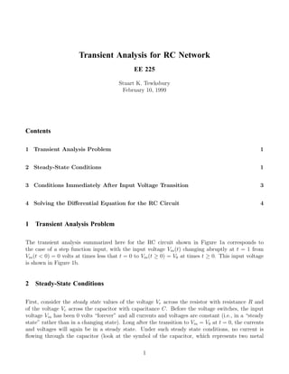
  • 1. Transient Analysis for RC Network EE 225 Stuart K. Tewksbury February 10, 1999 Contents 1 Transient Analysis Problem 1 2 Steady-State Conditions 1 3 Conditions Immediately After Input Voltage Transition 3 4 Solving the Differential Equation for the RC Circuit 4 1 Transient Analysis Problem The transient analysis summarized here for the RC circuit shown in Figure 1a corresponds to the case of a step function input, with the input voltage Vin (t) changing abruptly at t = 1 from Vin (t < 0) = 0 volts at times less that t = 0 to Vin (t ≥ 0) = V0 at times t ≥ 0. This input voltage is shown in Figure 1b. 2 Steady-State Conditions First, consider the steady state values of the voltage Vr across the resistor with resistance R and of the voltage Vc across the capacitor with capacitance C. Before the voltage switches, the input voltage Vin has been 0 volts “forever” and all currents and voltages are constant (i.e., in a “steady state” rather than in a changing state). Long after the transition to Vin = V0 at t = 0, the currents and voltages will again be in a steady state. Under such steady state conditions, no current is flowing through the capacitor (look at the symbol of the capacitor, which represents two metal 1
  • 2. Vin(t) Vr V0 + R Vin Vc – C V=0, t=0 time t (a) (b) Figure 1: (a) RC network. (b) Step function input voltage. Vr Vr + + R R Vin C Vc Vin C Ic – – (a) (b) Figure 2: (a) At DC, no current can flow through insulator between plates of capacitor and the capacitor in Figure 1a is replaced by an open circuit. (b) At extremely high frequencies no voltage develops across the capacitor and the capacitor in Figure 1a is replaced by an short circuit. plates and a perfect insulator, allowing no DC current flow, between the plates). We can therefore replace the capacitance by an “open circuit” as shown in Figure 2a.1 Must Know. * Under steady state conditions, no current can flow through a capacitor. A perfect insulator (infinite resistance) separates the two plates of the capacitor. Since no current is flowing in the steady state, there is no voltage drop across the resistor and the voltage at the right hand end of the resistor is exactly the same as the input, i.e., the steady state voltages Vr (ss) and Vc (ss) are as follows. Before the input voltage switches (i.e., for t < 0), Vr (ss) = 0 fort < 0 Vc (ss) = 0 fort < 0 1 As discussed in class, at very high frequencies there is insufficient time for a voltage to appear across the capacitance even though a current is flowing. For the high frequency case, the capacitor is replaced by a short circuit, as shown in Figure 2b. 2
  • 3. Long after the input voltage has switched (i.e., for t 0), Vr (ss) = 0 fort 0 Vc (ss) = V0 fort 0 These steady state voltages are shown in Figure 3a and b. The steady state conditions establish the boundary conditions used to complete some solutions of differential equations. Must Know. * The voltage across a capacitor can not change instantaneously. To determine steady state conditions, replace capacitor with an open circuit. An open circuit corresponds to no connection between the nodes. 3 Conditions Immediately After Input Voltage Transition We also need to easily see the initial value of the voltages Vr and Vc immediately after the transition (e.g., at time t = where > 0 is arbitrarily close to 0). The formal comment above means IMMEDIATELY after, rather than after a few nanoseconds, the INSTANTANEOUS change in the input voltage. The current-voltage behavior of a capacitor is i(t) = C · dVc /dt and, by integrating this equation, the voltage is 1 T =t Vc (t) = Vc (t = 0) + i(T )dT. (1) C T =0 Equation 1 shows that the voltage can not instantaneously change, for a finite current, and therefore, immediately after the input voltage Vin changes, the voltage Vc across the capacitance has not changed. In particular, Vc (t + ) = Vc (t − ). Since the voltage can not change instantaneously across the capacitor, all the voltage change initially appears across the resistor, establishing the conditions at t + shown in Figure 3. Must Know. * The voltage across a capacitor can not change instantaneously. * The current into a capacitor can change instantaneously. Note that if charge enters one side of the capacitor, equal charge leaves through the other side, having the effect of a current flowing “through” the capacitor. In Figure 3, the trend in Vr and Vc between the initial state immediately following the change in Vin is shown as dashed, shaded lines. The change is not linear but instead, as we shown next by solving the differential equation for the circuit in Figure 1a, exponential. 3
  • 4. 4 Solving the Differential Equation for the RC Circuit The Kirchoff voltage equation around the RC circuit in Figure 1a is given by Vin (t) = i(t) · R + Q(t)/C (2) where Q, the charge on the capacitor, is related to the current i(t) by i(t) = dQ(t)/dt or t Q= i(x)dx. (3) 0 Substituting (3) in (2) eliminates the variable Q, giving the following equation in terms of only Vin (t) and i(t): 1 t Vin (t) = i(t) · R + i(x)dx. (4) C 0 We can eliminate the integral in (4) by differentiation, leading to dVin (t) di(t) 1 =R· + i(t). (5) dt dt C Since Vin (t > 0) = V0 , V0 a constant, dVin /dt ≡ 0 and (following division by R), (5) becomes di(t) 1 + i(t) = 0. (6) dt RC Vr (t = 0 + ε) Vr (t = ∞) s ase al cre erenti s. dec Resi e in f Voltage e dif reas stor ag dif ng f e v olt olve it cha v S fin erent s to z oltag or ow d h ial e e cit e. ow equ ro.So pa valu ind h a l it c atio lve C a o f han n t fin n t ges o to uatio . eq Vr, Vc Vc (t = ∞) t=0 Time t Vc (t = 0 + ε) Figure 3: Illustration of voltages in RC circuit including (i) voltages appearing before the input voltage (Figure 1b) changes, (ii) voltages immediately after (t = 0+ ), and (iii) steady state voltages long after (t = ∞) the input voltage changes. The dashed, shaded lines represent the unknown behavior of the voltages between the initial and final states, requiring solution to the differential equation. 4
  • 5. We will use the parameter α = 1/(RC) in (6), giving the final equation that we will solve, namely, di(t) + α · i(t) = 0. (7) dt Rearranging terms in (7) gives di(t) = −α · dt. (8) i Integrating (8) gives, using the initial current i(t = 0 + ) = i0 , t di t = −α dt 0 i 0 ln(i(t)) − ln(i0 ) = −α · t or i(t) = i0 e−αt (9) Equation 9 shows that the current at time t = 0 starts with the value i(t) = i0 and “decays” to zero as t → ∞. However, we have not determined the value of i0 , the current flowing immediately after the input voltage changes. This is readily obtained by looking at Figure 3 where, since the voltage across the capacitor can not change instantaneously, the input voltage initially appears fully across the resistor. Therefore, the initial current is given by the voltage across the resistor (Vr (t = 0 + ) = V0 where V0 was the value of the input voltage after the switching) divided by the resistance R or i0 = V0 /R . Using this value of i0 in 9 gives the value of current in terms of the known input voltage and the resistance, i.e., V0 −αt i(t) = e R V0 −t/RC = e (10) R where we have replaced α by its definition α − 1/RC. The quantity RC has units of time (time in seconds if R is in ohms and C is in farads) and is usually called the RC time constant of the circuit. FINALLY! We are now able to give the solutions for the voltages across the resistor and capacitor indicated by the dashed, shaded lines in Figure 3. In particular, Vr (t) = i(t) · R = V0 e−t/RC (11) Vc (t) = V0 − Vr = V0 1 − e−t/RC (12) The number “e“ is equal to 2.72 (approximately). The voltage across the resistor decreases to 1/e of its initial value at t = RC (i.e., to 37% of its initial value in one time constant). In two time constants (t = 2 · RC, the voltage has decayed to 13% of its initial value. In four time constants, it has dropped to a little under 2% of its initial value. Figure 4 shows the voltages Vr (t) and Vc (t), 5
  • 6. Voltage V/V 0 1.0 Vc 0.8 0.6 0.4 0.2 Vr t=0 1 2 3 4 Time t/RC Figure 4: Exponential decay of voltage across resistor and exponential growth of voltage across capacitor of simple RC circuit in Figure 1a. showing the exponential characteristic shown earlier by the unknown dashed, shaded lines in Figure 3. Must Know. * The time dependence of the changes of voltages and currents in the simple circuit of 1a is exponential, of the form exp(−t/RC), where RC is the circuit’s “time constant.” * Initially, all the voltage is dropped across the resistor * After a long time (relative to τ = RC), all the voltage is dropped across the capacitor. * Initially, a current (initially limited by the resistance to V0 /R) flows. * After a long time, the current is zero. 6