Telecom SS7 basic
•Descargar como XLS, PDF•
6 recomendaciones•7,171 vistas

This Good file for understanding SS7 and STP..GSM basic

Recomendados
Más contenido relacionado
Destacado
Similar a Telecom SS7 basic
Similar a Telecom SS7 basic (20)
Último
Último (20)
Telecom SS7 basic
- 1. TELECOM BASICS E1 Voice Theorm Erlang a) 256 bytes per frame a) Voice Frequency ~ 300 to 3300 Hz , bandwidth = 4000 Hz a) Unit of Traffic descibes total traffic volume in one hour b) 8 bits Each TS in E1 Frame b) Nyquist theorm = Min 8000 sampling rate reqd ( 4000*2 ) b) Erlang = Busy time for ckts / Avl Time for measurment , Ex : 20/60 = 3Er c) 0.125uS time taken by one frame c) One Sample = 8 bits ( Reprsntation of 256 Voice Levels , 2 pow 8 = 15ckt - 8.1 Er 31ckt - 21.5 Er 3 E1 - 77 Er 10 E1 - 286 Er 20 - 592 d) Total 8000 frames in One Second 256) 30ckt - 20.3 Er 02 E1 - 48 Er 5 E1 - 136 15 E1 - 439 Er 30 - 901 d) 8000 samples in One Sec = 8 bits * 8000 = 64000 bits per sec required E1 Physical Interface CAS ( Channel Associated Signalling ) CAS Line Signalling a) 0th TS used for synchronization ( 0011011) a) Uses INBAND Signalling ( Voice frequencies ) a) Uses TS = 16 for indication of ckt. Status only ( I.e. b) Modes of Operation b) Signaliing Associated in that E1 only - TS = 16 Line Sig. And TS=All Registered Signalling FREE , SIEZ , FREE BY A/B , BUSY etc….) 1. Unframed - No TS at all 2. Framed - All 32 TS used for data ABCD Fwd ABCD Bckwd STATUS 3.Multiframe - 0 TS for sync, rest 31 for data CAS Registered Signalling 10XX 10XX IDLE c) Bit '1' - 3V , Bit '0' - 0~0.3 V Grp A Bwd Sig. Grp B Bwd Sig. 00XX 10XX SIEZ 1 Send Next Dig. 2 Changed No. 00XX 11XX SIEZ ACK CAS Registered Signalling 00XX 01XX ANS 2 Restart 3 Called Line Busy a) Uses voice TS for Registered Signalling . 00XX 11XX B PARTY REL 3 Change over grp B 4 Congestion 10XX 0/10XX A PARTY REL b) Types : DECADIC , DTMF , R2 Semi C , R2Fully 4 CLI 5 Unallocated No. C c) R2MF - R2 Multi Freq Fully Compled (Ack Reqd) 5 Send Cat of A Party 6 Normal subs free Ist Frame : TS-1 & TS-17 (4+4 bits) d) MF - Combination of 2 Freq to represent one info 6 Switch to speech IInd Frame : TS-2 & TS-18 Grp 1 Fwd Sig. Grp II Fwd Sig. 7 Send last but 2 digits .... 1 Digit '1' 1 Ordinary Subs 8 Send last but 3 digits .... 2 Digit '2' 2 Priority Subs 9 Send last but 1 digit 15th Frame : TS-15 & TS-31 3 Digit '3' 5 Operator 4 Digit '4' 6 STD Coin Box CCS Associated CCS Quasi associated CCS Non associated. CCS STRUCTURE
- 2. Layer-2 : CRC , Retransmission ( PCR ) , Error Correction and detection Etc CCS 7 Layers 8 7 1 7 1 6 2 8 Layer#2 FLAG BSN BIB FSN FIB LI SPARE DATA CRC 0 FISU Layer-3 : 1-2 LSSU b. Signalling Route Management - Traffic / Sharing / Overloading Routing 3-63 MSU c. Signalling Link Management - Control / Monitor / Status of Links e Signalling Traffic Management - Change over/ Back in case of Fail e. Alignment - SIO , SIN , SIE , SIOS f. Message Distribution - Distributing the MSG to ISUP , SCCP g. Message Discrimination - Mine or Other DPC / NW Layer#3 SIF SIO h. Message Routing - Linkset / DPC findout from Routing Table Service Indicator SubService Field Service Indicator 0 - SNM ( Signalling NW Management Message ) 1 - MTN ( Mtc Regular Msg ) 2 - MTNs ( Mtc Special Message ) 3 - SCCP ( Carry Non-Voice Traffic Ex: SMS ) 4 - TUP 5 - ISUP ( Voice related traffic ) Network Indicator Priority - 1,2,3 6 - Data User Part ( Call & ckt Related ) NAT0/1, INAT0/1 ( Low to High ) 7 - Data User part ( Facility Regn & Cancellation ) SLS ( 4 Bits Layer-3 Timers , Max 16 T1 Delay to avoid message mis-sequencing on changeover .5 to 1.2 sec. Selection ) CIC (only T2 Wait for changeover Ack .7 to 2. 0 sec DPC OPC USER PART Signalling ISUP) T3 Delay to avoid message mis-sequencing on changeback .5 to 1.2 sec. Link T4 Wait for changeback Ack (1st attempt) 5 to 1.2 sec. Selection T5 Wait for changeback Ack (2nd attempt) 5 to 1.2 sec. ISUP Message Type : IAM ( Initial Address Message ) INR ( Information Request ) ACM ( Address Complete ) ISUP Message Type Mandatory FIX Mandatory Variable Optional FIX Optional Variable ANM ( Answer Message ) REL ( Release Message ) RLC ( Release Complete ) BLO ( Blocking ) UBL ( Uublocking ) IAM A Party Category , Forward Call Indicator B Party No , User service Info CLI , Carrier , NW , HOPs BLA ( Blocking Acknowledment ) CPG ( Call Progress )
- 3. SCCP Message Type Mandatory FIX Mandatory Variable Optional FIX Optional Variable Used for Protocol Class : 1. Called Party UDT Class -0 : Basic Connectionless ( Non Critical, 2. Calling Party Used to transport user data and TCAP ) 3. User Data SCCP management messages in the Class -1 : Sequenced Connectionless (Critical User Data : connection-less mode. It can , TCAP ) 1. Called Party 1. Length Indicator Segment / DeSegment data as per its XUDT Class -2 : Basic Connection Oriented 2. Calling Party 2. User Data Ex: TCAP etc size ( BSSAP ) 3. User Data Class -3 : Flow Control Connection Oriented (BSSAP ) 1. Called Party Used to indicate to the originating 1. Return:Cause Class -4 Flow Control + Err Recovery UDTs 2. Calling Party 1. Segmentation data SCCP user that a UDT message 2. Hop Counter Connection Ori. 3. User Data cannot be delivered to the specified destination. The data field of the UDT 1. Called Party message and the reason for the 1. Return Cause XUDTs 2. Calling Party 1. Segmentation data return are included in the UDTS 2. Hop Counter 3. User Data message. Connection Oriented - Only used in BSSAP where heavy data transfer is required for ex. Between MSC/VLR to BSC to BTS Calling / Called party : 1. Address Indicator : a. Routing Indicator : GT based or ( DPC + SSN ) b. GTT Indicator : No GT or GT - 1 or 2 or 3 or 4 c. SSN Indicator : Present / Not Present d. Point Code Indicator : Present / Not Present 2. Address : a. Point Code b. SSN c. GT - 1 : i. Nature of Address Ind : Subscriber Number / National Sig. No. / International No. ii. Odd / Even Indicator ( Spr) iii. Address Information ( 919839212499 ) d. GT - 2 : i. Translation Type ii. Address Information ( 919839212499 ) e. GT - 3 : i. Translation Type ii. Encoing Scheme - Unknown / BCD Odd / BCD Even iv. Address Information iii Numbering Plan - ISDN / Telephony / Data / Telex / Land Mobile / Mobile e. GT - 4 : i. Translation Type ii. Encoing Scheme - Unknown / BCD Odd / BCD Even iii. Numbering Plan iv. Nature of Address Indicator v. Address Information ( Contains Address for Example : 919839212499 )
- 4. SCCP - Routing Protocol SCMG Functions - Signaling point status management : Failure, recovery, and congestion information of signaling points, provided by MTP - Subsystem status management : Subsystem failure and recovery information, and SCCP (SSN 1) congestion received in SCCP management messages. - Subsystem status test : SSP , SSA , SST , SOR , SOG SSN 1 SCCP Management 3 ISDN user part 4 OMAP (Operation, Maintenance and Administration Part) 5 MAP (Mobile Application Part) 6 HLR (Home Location Register) 7 VLR (Visitor Location Register) 8 MSC (Mobile Switching center) 9 EIR (Equipment Identifier register) 10 AUC (Authentication Centre) 11 ISDN Supplementary Services (SSAP) 13 Broadband ISDN edge-to-edge applications 254 Base Station System Application Part (BSSAP) Hop Counter ( 15 to 1 ) : Counter is decremented upon GTT Segmentation : Max 16 Segments , each carries 246 bytes GTT CASES 1. SPC + SSN 2. SPC + SSN + GT 3. SSN + GT 4. SPC + GT 5. GT only GT is performed on given SPC + SSN on the basis of GT info , to find out the final A/B Party Address
- 5. GTT > Method of hiding the SS7 point code and sub-system number from the originator of a message a) GT Consists of – Translation type (TT) – Numbering plan (NP) – Nature of address (NA) – Global title digits (GTDIG) b) GT Benefits – Central administration of routing information makes it easier to restructure the network – It is possible to set up alternative routing schemes and load sharing – More compact and dyanmic routing tables – The function is required for the introduction of certain new services (such as call completion to busy subscriber, CCBS and 800 free phone) a) The result of a global title translation can be: – the point code for a signaling destination – a subsystem service group ( this is used in the intelligent network to guarantee a fail-safe service control point (SCP). Two SCPs can be combined to form a subsystem service group that is accessed from the relevant service switching point (SSP) via global title translation. ) – a translator service group ( this consists of up to four signaling points, each of which can perform the necessary translation ) – a further translation in the same network node
- 6. Functions of TCAP are to control: TRANSACTION DIALOG TAG COMPONENT TAG · The transaction between both endpoints in the network · The communication to the users of TCAP. TCAP : 1. Transaction Part : ( Deals with SCCP Message ) a. TCAP Message Type : BEGIN / UNI / END / CONTINUE / ABORT b. Length Indicatior of Transaction Tag ( Max 2048 , SCCP takes Care of Segmenting / Breaking ) c. Transaction Info ( Not Valid for UNI ) i. Origination Transaction Id ( Mandatory for BEGIN , CONTINUE ) - Length Indicator & Value i. Destination Transaction Id ( Mandatory for END , ABORT , CONTINUE ) - Length Indicator & Value i. P_Abort Cause ( Mandatory for TC_P_Abort Request ) - Reason for Abort 2. Dialog Part : a. Dialog Indicator Tag b. Length Indicatior of Dialog Tag c. Dialog Information - Depend on USER For Ex : MAP , INAP 3. Message Component Part : ( Deals with USERs such as MAP , INAP ...) a. Component Indicator Tag b. Length Indicatior of Component Tag c.Component Type : ( Invoke / Return Result Last / Return Result Not Last / Return Error / Reject ) d. Component length e. Component User Information by MAP , INAP , CAMEL , OMAP , SSAP Etc.......... Message type Function Invoke Initiates/invokes a desired operation at the remote peer application entity. Return result not last Used to carry a segment of the result of a successfully completed operation. It is used when a success reply is physically too large to fit into a single message. Return result last Represents the final success reply to an operation invocation. If the success reply was segmented, this component would represent the final segment of the reply Return error Indicates an operation invoked previously has failed due to some processing error. Error codes are supplied by TCAP users, and are passed transparently by TCAP. Reject Indicates that one of the Invoke, Return Result, or Return Error components received from the remote user/CSL could not be understood or was not expected. Unidirectional Used to transport data in an unstructured dialogue Begin First message, to start a structured dialogue, sent once Continue Used to sustain the structured dialogue, more continue messages can be sent End Used to terminate the structured dialogue in a normal way Abort Used to terminate the structured dialogue in an off normal way.
- 7. SMSC HLR 1. SMS are stored in SMSC before they can be sent to MS ( 140 bytes each SMS ) 2. MAP USED is > Forward Short Message Submit TCAP Begin/Invoke - SRI for SM > Send Routing Info for SM TCAP End / Retrun Res - SRI Ack MSISDN > Forward Short Message Deliver 3. MO Forward SM : A party MS to SMSC ( Forward Short Message Submit ) 4. MT Forward SM : SMSC to B Party MS ( Forward Short Message Deliver ) TCAP Begin/Invoke - Forward SM TCAP End / Retrun Res - Forward SM Ack GMS MSC/VLR C SM_DELIVER BTS
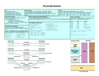
- 8. BTS G VLR V A L B D D R C E HLR M GMSC S IMSI GSM C Overview F H IMEI AUC-SIM SMSC EIR HLR TCAP Begin/Invoke - Provide MSRN TCAP Begin/Invoke - SRI TCAP End / Retrun Res - MSRN Ack TCAP End / Retrun Res - SRI Ack MSISDN IAM - MSISDN GM MSC/VLR SC BTS IAM - Mobile Terminating Call ( MTC ) MSISDN STP STP SCP A-Access B-Bridge Other STP NW C-Cross D- C-Cross Service Control Pt Diag onal SCP STP STP A- Acce ss A- E-Extended Acces C7 Network s SSP (Service Switching Pt )
- 9. GPRS ( General Packet Radio Services ) a) Key Features Speed immediacy New applications Better applications Service access b) Key Network Features of GPRS Packet switching Spectrum efficiency Internet aware Supports tdma and gsm c) Limitations of GPRS Limited cell capacity for all users Speeds much lower in reality Support of gprs mobile terminate by terminals is not ensured Suboptimal modulation Transit delays No store and forward d) SGSN - Serving GPRS Support Node handles session management, mobility management, billing and traffic measurements bit level encryption of data which is to be sent over the air interface. Put GPRS data received from the BSC in IP format for sending to the GGSN and vice-versa. Provide GPRS routing to BSC’s d) GGSN - GPRS Gateway Support Node The GGSN is the gateway in and out of the GPRS system. It routes packets from an external network ( "the Internet" ) to the SGSN which is currently serving the MS, and routes packets from the SGSNs to which it is connected to the external network. This concept is called tunnelling. d) Similar Techniques Enhanced Data rates for GSM Evolution (EDGE) Universal Mobile Telephone System (UMTS)
- 10. FLAG UDT MESSAGE PROTOCOL CLASS = TRANSACTION ID , BEGIN BSN DPC B PARTY/ -1GT(N) / 0 BIB A SSN / SUB NO / PARTY - GT(N) DIALOG ID FIB SSN / SUB NO FSN COMPONENT TYPE = INVOKE LI OPC SIO USER DATA SIF COMPONENT USER DATA , MT Forward SM , SPARE USER DATA MSIN DIGIT CRC SLS MTP - 2 LAYER 3 SCCP TCAP GSM Overview BTS IMSI : International Mobile Subs Identity [ SIM , MCC(3) + MNC(2) + MSISDN G (<10) ] VLR VLR A TMSI : Temporary Mobile Subs Identity [ VLR , MCC(3) + MNC(2) + MSISDN B (<10) ] D D MSISDN : Mobile Stn Integrated Services Digital NW [ CC(1-3) + NDC(1-3) + MDN(10) ] C E HLR MSC GMSC MSRN : Mobile Subs Roaming Number [ VLR , CC(1-3) + NDC(1-3) + IMSI MDN(10)TMSI IMSI Vs ] F GSM Overview IMEI can't take hacking benefits with TMSIBy Nokia ] One : International Mobile Eqpt. Identity [ as it is dyanmically allocated by AUC- IMEI LAI : , moreover TMSI is 4 octet shorter than IMSI+. LAC(<10) ] VLR Location Area Identifier [ MCC(3) + MNC(2) SIM H EIR MAP D ( HLR-VLR ) MAP C ( HLR-MSC ) MAP E ( GMSC - MSC ) Provide MSRN / MSRN Ack Send Routing info SRI / Process access sigmnalling CCS 7 SMSC Update Location / Cancel Location / Ack Ack Forward access Signalling CCS 7 Insert / Delete Subs Data / Ack Send Routing info for Send End Signal CCS 7 MAP I ( Subservices - MSC ) Send Param / Ack SM / Ack Perform Handovers / Subsequent HO Get Pwd / Register Pwd Reset Set Message waiting Perform Internal Handovers Activate / Deactivate / Erase / Register SS Deregister Mobile Data data Trace subs activity Interrogate / Invoke SS Note MS Present Alert Service Centre Forward SS Notification Regisster charging info MAP F ( EIR - MSC ) MAP H ( SMSC - MSC ) MAP G ( VLR - VLR ) Check IMEI Forward Short Message Send Param Intelligent Network ( IN ) Requirement / Advantages Rapid deployment of Vendor / SSP Free Services which are centrally administered SSP CCF - Call Control Functions ( Takes Care of all call related processing in Switch ) SSF - Service Switching functions ( Provides IN Triggering and IN Accessibility ) SRF - Specialized resource function ( Provides interactioon bw Call processing SW in SSP) SCP SCF - Service Control Functions ( Executes IN service logic and interfaces witrh SSP via SSF ) SDF - Service data function ( Maintains all customer and nw data ) SMP - Service Management Point ( Administration and Operation of IN ) SIB - Service Independ Service Blocks ( Generic purpose reusable software codes in IN ) BCP - Basic Call Process SCEP - Service Environment creation function ( Allows sevices in IN to be defined , tested ... )
- 11. Erlang a) Unit of Traffic descibes total traffic volume in one hour b) Erlang = Busy time for ckts / Avl Time for measurment , Ex : 20/60 = 3Er 15ckt - 8.1 Er 31ckt - 21.5 Er 3 E1 - 77 Er 10 E1 - 286 Er 20 - 592 30ckt - 20.3 Er 02 E1 - 48 Er 5 E1 - 136 15 E1 - 439 Er 30 - 901 CAS Line Signalling a) Uses TS = 16 for indication of ckt. Status only ( I.e. FREE , SIEZ , FREE BY A/B , BUSY etc….) ABCD Fwd ABCD Bckwd STATUS 10XX 10XX IDLE 00XX 10XX SIEZ 00XX 11XX SIEZ ACK 00XX 01XX ANS 00XX 11XX B PARTY REL 10XX 0/10XX A PARTY REL Ist Frame : TS-1 & TS-17 (4+4 bits) IInd Frame : TS-2 & TS-18 .... .... 15th Frame : TS-15 & TS-31
- 15. s (GTDIG) busy subscriber, CCBS and 800 free phone) e control point (SCP). Two SCPs can be combined to form a subsystem service group that is accessed from m the necessary translation )
- 16. Functions of TCAP are to control: · The transaction between both endpoints in the network · The communication to the users of TCAP. r application entity. completed operation. It is used when a success reply is physically too large to fit into a single message. ocation. If the success reply was segmented, this component would represent the final segment of the reply ue to some processing error. Error codes are supplied by TCAP users, and are passed transparently by TCAP. urn Error components received from the remote user/CSL could not be understood or was not expected. e e messages can be sent way mal way.
- 19. -versa. ently serving the MS, This concept is called tunnelling.
- 20. GMSC MAP I ( Subservices - MSC ) Get Pwd / Register Pwd Activate / Deactivate / Erase / Register SS Interrogate / Invoke SS Forward SS Notification
- 21. SMS FLAG UDT MESSAGE TRANSACTION ID , BSN PROTOCOL CLASS = 0 / 1 BEGIN DPC BIB B PARTY - GT(N) / SSN / SUB NO DIALOG ID FIB A PARTY - GT(N) / SSN / SUB NO FSN COMPONENT TYPE LI = INVOKE OPC SIO SIF USER DATA COMPONENT USER USER DATA , SPARE DATA MT Forward SM , CRC SLS MSIN DIGIT MTP - 2 LAYER 3 SCCP TCAP
- 22. Some Useful Definitions:- PROTOCOL:- It is a set of rules governing the way, the data will be Tx and Rx over the data communication network. Protocls must provide reliable, error free transmission of user data as well as network managament functions. PRIMITIVE:- A primitive is an interface which provides access from one level of protocol to another level of protocol. In the case of Dbase, the Dbase is considered as an application entity and the protocol used to acccess and interface to this application is TCAP. CIC:- It is of 16 bits of which 4 bits are spare MTP-2 Functionalities… 1) S.U. Delimination.. Flag…01111110… Correct start and end of SU… If not bit insertion is used. ie No " 1s density " violation should be there. If its there then Bit stuffig is used. 2)S.U. Alignment SU should be received in sequence SU must be a multiple of 8 Conditions for error free transmission SIF of MSU should not exceed 272 octet capacity SUERM: Signalling unit error rate monitor Counter used to check the max number of errors on a 64Kbps SDL Each link keeps its unique couter When the number of errors increase the threshold limit then the link is taken out of service. Error due to clock signals being not synchronised prperly at Tx and Rx L-3 ( Realigns the Link, by taking the link out of service) L-2 (Reports any error to L-3 link Mgmnt) This phenomena is called the"Alignment Procedure" phenomena
- 23. nication network. evel of protocol. ess and interface ut of service.