
Recomendados
Más contenido relacionado
La actualidad más candente
La actualidad más candente (20)
Similar a Construction of bukit berapit twin bore pipe arch tunnel
Similar a Construction of bukit berapit twin bore pipe arch tunnel (20)
Último
Último (20)
Construction of bukit berapit twin bore pipe arch tunnel
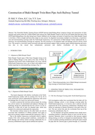
- 1. Construction of Bukit Berapit Twin-Bore Pipe Arch Railway Tunnel D. Hall, V. Chow, K.C. Lin, Y.Y. Low Gamuda Engineering Sdn Bhd, Petaling Jaya, Selangor, Malaysia. don@2t.com.my, wschow@2t.com.my, kclin@2t.com.my, yylow@2t.com.my Abstract: The Electrified Double Tracking Project (EDTP) between Ipoh-Padang Besar comprises design and construction of infra- structure and system works for a 329km double track railway line. Bukit Berapit Tunnel is one of two rail tunnels that form part of the EDTP Ipoh-Padang Besar, the other being Larut Tunnel. Dubbed to be the longest rail tunnel in South-East Asia, Bukit Berapit Tunnel is twin-bore, 2.9km in length and horse-shoe shape in cross section. Its alignment necessitates multiple river diversions, a road diver- sion and microtunneling crossings under the North-South Expressway. For construction of Bukit Berapit Tunnel underneath the ex- pressway, two microtunnelling crossings are required. The first crossing is a 3m diameter triple cell drainage culvert to divert a local river. The second is a twin-bore tunnel excavated with pipe arch primary support. Both crossings require detailed planning and execu- tion due to the mixed face embankment, proximity and shallow overburden of the expressway. 1 INTRODUCTION Triple 3m diameter 1.1 Alignment of Bukit Berapit Tunnel drainage culvert Bukit Berapit Tunnel spans 2.9km from Changkat Jering in the north to Padang Rengas in the south in the state of Perak. Its alignment criss-crosses with a Federal Route, two rivers, and the North-South Expressway twice, one of them with shallow over- burden requiring two microtunnelling crossings. (Fig. 1) Existing twin 3mx3m Twin-bore railway drainage culvert to be tunnel with pipe arch demolished & replaced Fig. 2. Three-dimesional plan view of Bukit Berapit microtunnel- ling crossings at North-South Expressway 2 CONSTRUCTION OF TRIPLE CELL 3M DIAMETER Fig. 1. Alignment of Bukit Berapit Tunnel DRAINAGE CULVERT The tunnel alignment with shallow overburden at the North- 2.1 The New Drainage Crossing under North-South Expressway South Expressway clashes with an existing twin 3m by 3m in cross section box culvert underneath the expressway with serves for drainage flow of a local river and several streams. Soil investigation studies have ascertained that the triple cell 3m In order to construct the twin-bore railway tunnel, the existing diameter drainage culvert, a new drainage crossing under the box culvert needs to be demolished and replaced. Drainage and North-South Expressway, is to traverse only in alluvial soil and hydrology design has indicated that the box culvert is to be re- engineered fill of the expressway embankment. Boreholes have placed by a triple cell of each 3m diameter pipe, which also shown no indication of granite formation in the path of the cul- needed to be constructed underneath the expressway. vert. The new culvert has only 4m overburden from top of the The twin-bore railway tunnel on the other hand, can only be expressway embankment. (Fig. 3) excavated after installation of 780mm diameter steel pipes or A 3.5m diamater soft ground cutterhead slurry shield micro- pipe arch as primary support underneath the expressway. (Fig. 2) tunnelling machine is therefore chosen to carry out the the con- Due to the shallow expressway overburden which is approx- struction. Bentonite slurry is provided as face pressure support imately 4.0m with varying ground conditions, construction of during mining, as well as, to transport out mined materials. There both drainage and railway tunnel crossings underneath the ex- is also an annulus grouting mechanism to fill up the space around pressway embankment require special method and expertise. the pipe after the concrete pipe is jacked through, as a consolida-
- 2. tion measure. (Fig. 4 and 5) A temporary sheet pile cofferdam has had to be constructed on each side of the expressway embankment, in order to act as thrust and receiving shafts, as well as allow just enough room to lift out the microtunnelling machine to continue mining each concrete pipe. The total jacking length of each 3m diameter concrete pipe averages about 45.5m. Continuous monitoring by optical targets installed on the ex- pressway embankment is carried out in order to monitor any sur- face settlement on the embankment during mining. The construction of the triple cell 3m diameter concrete pipes has been successfully completed. The pipes now act as a drainage Fig. 6. Completed triple cell 3m diameter drainage pipes culvert to divert the local river and streams that have been flow- ing through the existing twin box 3m by 3m in the alignment of the Bukit Berapit Tunnel. (Fig. 6) 3 DEMOLITION OF EXISTING TWIN BOX CULVERT 3.1 The Old Drainage Crossing under North-South Expressway With the triple cell 3m diameter drainage culvert now all ready to replace the 3m by 3m twin-box, old drainage crossing, demoli- tion is ahead to make way for the Bukit Berapit Tunnel. However, as an existing structure underneath the highway em- bankment, its demolition is to be carried out step-by-step and mainly to be rid of the steel bar reinforcement at the side walls and base slab where it will clash with the tunnel. Demolition se- quence also calls for pressurized cementatious injections in order to solidify the embankment surrounding the box culvert. (Fig. 7) After the step-by-step demolition, the twin box culvert is eventually sealed off with lean concrete filling for the construc- Fig. 3. Longitudinal profile (top) and cross section (bottom) of tion of the twin-bore pipe arch tunnel. (Fig. 8 and 9) the triple cell drainage culvert Fig. 4. One of the 3m diameter concrete pipes in microtunnelling Fig. 7. Plan (top) and cross section (bottom) of the demolition action sequence Fig. 8. Demolition by coring & hacking to rid of reinforcement Fig. 5. Breakthrough of one of the 3m diameter drainage pipes for twin-bore pipe arch tunnel construction
- 3. 4.2 Pipe Arch Microtunnelling Machine Explained The microtunnelling machine of 800mm outer diameter is of slur- ry shield type. This means it has bentonite slurry being pumped to the front of the machine from behind the cutterhead for face stabilization and to transport out mined materials. Laser guidance serves to lead the machine’s steering and advance. The machine and the 780mm outer diameter steel pipes of 10mm thick are jacked horizontally by two-stage hydraulic jack cylinders. The microtunneling machine also comes with a retraction mechanism when rock or obstacles are encountered. Normally, reaching the receiving shaft allows machine maintenance and changing of worn out cutterdiscs. When encountering obstacles Fig. 9. Sealing by lean concrete filling of the 3m by 3m existing however, there is a risk of the machine being jammed and be- twin box culvert come completely damaged even before reaching the receiving shaft. This mechanism is extremely useful at the right bore where bedrock profile is high. 4 CONSTRUCTION OF TWIN-BORE PIPE ARCH Every advance behind the machine is a string of 6m length RAILWAY TUNNEL steel pipes each one to be welded successively by MIG welding after every jacking. (Fig. 12) The annulus of the jacked-in steel 4.1 The Railway Tunnel Crossing under North-South Expressway pipe is grouted to consolidate the outside surrounding. Once the machine breaks through at receiving shaft, the microtunnelling machine is dismantled and transported back to the jacking shaft The concept of the pipe arch tunnel is referring to steel pipes of for the next drive until the maximum possible number of drives 780mm diameter acting as primary support that need to be in- for the pipe arch is completed. The maximum possible number of stalled first before the tunnel can be excavated. drives per pipe arch tunnel is 20 ± 7 steel pipes depending on the Before construction of the steel pipe arch and eventually the geology. (Fig. 13) tunnel can be carried out, extensive soil investigation is commis- sioned. Apart from drilling borehole on each of four shafts at the embankment, seismic refraction and resistivity surveys, laborato- ry tests, as well as probe holes also help to investigate the geolog- ical profile beneath the expressway. (Fig. 10 and 11) The soil investigation shows granite formation on each left and right bore of the twin-bore railway tunnel. Higher bedrock profile on the right bore requires a combination of methods of umbrella tubes cum steel ribs installation and rock splitting cum manual excavation before microtunnelling and full face excava- tion can be carried out. Rock splitting is required at high bedrock profile as blasting under the expressway is not allowed. Fig. 12. The microtunnelling machine with retraction mechanism (top) and successive welding of the 780mm diameter steel pipe Fig. 10. Left-bore profile of twin-bore pipe arch railway tunnel Fig. 13. Typical cross section of the twin-bore pipe arch tunnel Fig. 11. Right-bore profile of twin-bore pipe arch railway tunnel with 20 ± 7 steel pipes of 780mm diameter
- 4. 4.2 Pipe Arch Tunnel in Progress The microtunnelling machine is launched from the jacking shaft excavated within a three-sided 1 m diameter bored pile wall and a thrust wall for the jacking. The receiving shaft consists of similar three-sided bored pile wall. The jacking and receiving shafts have to be excavated in each stage of 2m depth for each possible num- ber of drives. (Fig. 14) Before microtunnelling operation, the perimeter of 800mm diameter in steel bar and shotcreted reinforcement of the bored pile wall starting face have be cored and hacked out on each of the receiving and jacking shaft to prepare as soft eye for the mi- crotunnelling advance and breakthrough. (Fig. 15) Fig. 15. The soft eye prepared for microtunnelling advance Where the bedrock profile is high at the right bore, an addi- tional primary support of mini pipe arch consisting of 61 ± 34 numbers of horizontal umbrella tubes at 24m length, 139mm di- ameter and 10mm thick fully grouted have to be installed first to secure the weathered granite at top of the bedrock. (Fig. 16) The tunnel is then mined in by rock-splitting method in pro- gression of 1m advance. After the rock face is drilled with a se- ries of holes of 110mm diameter, a hydraulic splitter is inserted inside the drilled holes to split open the rock. On completion of every 1m advance of mining, a single steel rib of 203 x 135 x 31mm (31.3kg/m) is installed. Bullflex strip of 320mm diameter by 12m length is then installed on top of the steel rib and inflated with pressurized grout to provide immediate support. Crown face of the tunnel at the steel rib is then shot- creted 200mm thick with double layers of BRC A6. Fig. 16. Installation of mini pipe arch ongoing This mini pipe arch operation is repeated until it has mined in 20m. The rock face is also further secured with 6m length rock bolts for complete stabilization in order for the pipe arch micro- tunnelling machine to breakthrough at this face of the receiving shaft. (Fig. 17) The extent of steel pipe from jacking to receiving shafts aver- ages about 90m in length. Total length of all steel pipes to be jacked in for each left and right bore of pipe arch tunnel is more than 2700m. The internal of the pipes are to be backfilled with lean concrete before commencing excavation of the tunnels. (Fig. 18) Once the pipe arch of 780mm diameter steel pipes have been completely installed, the tunnel will be able to be excavated un- derneath the expressway embankment every 1m in advance with double steel rib of 203 x 135 x 31mm (31.3kg/m), supported by bullflex and shotcrete. Fig. 17. Installation of single steel rib ongoing During the progress of pipe jacking, the surface of the ex- pressway embankment is monitored by optical targets. Fig. 18. Installation of pipe arch ongoing Fig. 14. The thrust wall and three-sided bored pile wall forms jacking shaft for microtunnelling
- 5. 5 CONCLUSION It is quite a challenge to construct a twin-bore tunnel through such varying geology in shallow overburden. Debris from the ex- pressway embankment such as tree trunks and steel bars apart from soil and gravels are not uncommonly encountered during microtunnelling. Excavation of the tunnel under a live express- way also calls for innovative construction methods, as well as ex- treme caution. At the time of writing, microtunnelling works is still ongoing on the right bore of the Bukit Berapit twin-bore railway tunnel. The construction process calls for close cooperation and teamwork amongst all members of the site team. ACKNOWLEDGMENTS The authors would like to express their gratitude to Keretapi Ta- nah Melayu Bhd (KTMB), Projek Lebuhraya Utara-Selatan Bhd (PLUS) and the whole site team of MMC-Gamuda Joint Venture Sdn Bhd based at Package N6 of EDTP Ipoh-Padang Besar, in- volved in the construction of the twin-bore, pipe arch railway tunnel.