SlideShare una empresa de Scribd logo
1 de 41
Descargar para leer sin conexión
111111 1111111111111111111111111111111111111111111111111111111111111
c12) United States Patent
Mello et al.
(54) SURFACE CHARACTERIZATION BASED ON
OPTICAL PHASE SHIFTING
INTERFEROMETRY
(75) Inventors: Michael Mello, Pasadena, CA (US);
Ares J. Rosakis, Altadena, CA (US)
(73) Assignee: California Institute of Technology,
Pasadena, CA (US)
( *) Notice: Subject to any disclaimer, the term ofthis
patent is extended or adjusted under 35
U.S.C. 154(b) by 320 days.
(21) Appl. No.: 12/203,050
(22) Filed: Sep.2,2008
Related U.S. Application Data
(60) Provisional application No. 60/967,297, filed on Aug.
31, 2007, provisional application No. 60/993,657,
filed on Sep. 12, 2007, provisional application No.
60/967,296, filed on Aug. 31, 2007, provisional
application No. 60/999,006, filed on Oct. 15, 2007.
(51) Int. Cl.
GOJB 11102 (2006.01)
GOJB 9102 (2006.01)
(52) U.S. Cl. ......................... 356/512; 356/520; 356/521
(58) Field of Classification Search ................. 356/35.5,
356/489,495,512,520,521
See application file for complete search history.
Probe beam
I Sample surface
module
20
1Q
US007990543B1
(10) Patent No.: US 7,990,543 Bl
Aug. 2, 2011(45) Date of Patent:
(56) References Cited
U.S. PATENT DOCUMENTS
6,031,611 A
6,268,883 B1
6,469,788 B2
6,781,702 B2
7,363,173 B2
7,487,050 B2
7,538,891 B1 *
7,760,363 B2 *
2002/0012122 A1
2003/0106378 A1
2005/0030551 A1
2005/0278126 A1
2006/0039007 A1 *
2006/0146342 A1 *
2006/0276977 A1
2007/0019203 A1 *
2007/0180919 A1
* cited by examiner
212000 Rosakis et a!.
7/2001 Zehnder eta!.
10/2002 Boyd eta!.
8/2004 Giannakopoulos eta!.
4/2008 Rosakis et a!.
212009 Rosakis et a!.
5/2009 Mello eta!. ................... 356/520
7/2010 Chen eta!. .................... 356/491
112002 Boyd eta!.
6/2003 Giannakopoulos eta!.
2/2005 Rosakis et a!.
12/2005 Rosakis eta!.
2/2006 Kim et al...................... 356/495
7/2006 Doerband eta!. ............ 356/512
12/2006 Rosakis eta!.
112007 Jansen .......................... 356/495
8/2007 Rosakis et a!.
Primary Examiner- Michael A Lyons
(74) Attorney, Agent, or Firm- Perkins Coie LLP
(57) ABSTRACT
Apparatus, techniques and systems for implementing an opti-
cal interferometerto measure surfaces, including mapping of
instantaneous curvature or in-plane and out-of-plane dis-
placement field gradients ofa sample surface basedonobtain-
ing and processing four optical interferograms from a com-
mon optical reflected beam from the sample surface that are
relatively separated in phase by rri2.
17 Claims, 23 Drawing Sheets
100
101
')Optical
201
Wavefront shaped by
~ sample surface
probe beam
Phase-shifting
interferometer
30
I
I
301
Phase-shifted
interferograms
501
!~I
Surface map;
Slope map;
Strain map; etc.
' )Phase map Surface map
'----pr_o_~_eo_ss_o_r_ __, r····.___p_r_oc-5e_os_s_o_r----'~ - .....
401
Phase map
Probe beam
m~d0ule J J
101 JOptical
probe beam
FIG. 1(a)
- Sample surface
20
.~100
/
201
Wavefront shaped by
~ sample surface
~
Phase-shifting
interferometer
30 301
Phase-shifted
1 interferograms
I
i~I
I
'Phase map
I pro~e;sor ~--------
( 401
Phase map
Surface map
processor
50
501
Surface map;
Slope map;
Strain map; etc.
)_.,.
~
00
•
~
~
~
~
=~
~
~
N~
N
0
........
rFJ
=-('D
('D
......
....
0
......
N
(,H
d
rJl
-....l
c
C
=u.~
w
=""""'
FIG. 1(b)
Phase-shifting
interferometer
30
10-1~

laser
101
Optical
probe beam11
Telescope

Wavefront shaped by ""'
sample surface
or sample wavefront
/
Beam splitter
.12.
Sample surface
20
~
00
•
~
~
~
~
=~
~
~
N~
N
0
........
rFJ
=-('D
('D
.....
N
0
.....
N
(.H
d
rJl
-....l
c
C
=u.~
w
=""""'
FIG. 1(c)
10-2-
Phase-shifting
interferometer
Telescope
.1Q
I.____3_0------~~v
~201Wavefront shaped by
sample surface
or sample wavefront
101-1 101
i
Mirror Optical
.. 1± j probe beam
'111!!1 "'>- X. i<:: ',~ I laser I
1 11
Polarizing
13

' beam splitter
Sample surface 101-2
w/ grating
22
~
00
•
~
~
~
~
=~
~
~
N~
N
0
........
rFJ
=-('D
('D
.....
(.H
0
.....
N
(.H
d
rJl
-....l
c
C
=u.~
w
=""""'
FIG. 1(d)
Sample surface
20
a
x2
101
(Optical
J .probe beam
I
I
I
I
(12 :
I
I
~ 205
/ Sheared
wavefront
.;/" L...............L.~
·:···············v·························[/···············f······················~ x3
../ ,/' _ ) ~I I
b
I , i~~~
······· 201
Wavefrontshapedby G1-71 G2-72
sample surface
or sample wavefront
10-1 ~,
',.........
_1 01
201
~
00
•
~
~
~
~
=~
~
~
N~
N
0
........
rFJ
=-('D
('D
.....
.j;o.
0
.....
N
(,H
d
rJl
-....l
c
C
=u.~
w
=""""'
FIG. 1(e)
Sample surface
w/ grating
22
a
x2 101
/ " - Optical
j . probe beam
~ 205
../ Sheared
wavefront
v-----j/r'~:=_t--·
- I I
x3
b
a
'
201 _ )
Wavefront shaped by
sample surface
or sample wavefront
10-2
u2{!~ 
_/
: ~
a' :! 201
:'-----y----J:I I
I 11 I
I I
G1-71 G2-72

'
2la_______... ~ ·¥' • ~'  •I A.+
..c-r101
201
~
00
•
~
~
~
~
=~
>=~
N~
N
0
......
......
rFJ
=-('D
('D
......
Ul
0
.....
N
(.H
d
rJl
-....l
c
C
=u.~
w
=""""'
Sample surface
20 or 22
.......
.....
201
..
2011
2012
sample wavefront~
@time tx •
FIG. 2(a)
...
.......Q)
E .
i=·
'
013
2014
~/
71
I
.....
.....
.....
.....
~30a
Phase map
processor
. 40
72
.....
.....
.....
.....
3011
-------------~ t1=0
3012 .
-------------~ t2=.6.t
~
301x
Corresponding
phase-shifted
interferogram
3013
-------------~ t3=2.6.t
3014
-------------~ t4=3~t
'
~
00
•
~
~
~
~
=~
~
~
N~
N
0
........
rFJ
=-('D
('D
.....
0
0
.....
N
(.H
d
rJl
-....l
c
C
=u.~
w
=""""'
U.S. Patent Aug. 2, 2011 Sheet 7 of23 US 7,990,543 Bl
FIG. 2(b)
/-200
Obtain a sample wavefront 0 20
+
j=1 t=O, J
(~)
Induce a phase shift of the sample wavefront 2
~j(tj)=~(tj)+U-1 )n/2
~
30
+
Induce a lateral shear of the phase-shifted wavefront 2
d/dx1 or d/dx2
~
31
+
Obtain a fringe pattern of the sheared wavefront 2
lj(tj)=lm(tj)+la(tj)COS~j(tj)
~
32
+
j=j+1; tj=U-1 )M
A
N~J>4 y
I Output: ps11(t1), 12(t2), 13(h), 14(4)
+
Obtain the phase map ~(t1)
0assuming ~(t1)=~(t2)=~(t3)=~(4)
40
Probe beam
m~~ule v
101
Optical
probe beam
501
Surface map;
Slopemap; 
Strain map; etc. 1
-+---
FIG. 3
Sample surface
20
lr
Wavefront
replicator
60
Surface map
processor
50
-300
~
201
601
Four copies of the
.( sample wavefront
~
-__..
...
...
__..
Phase-shifting
interferometer
35
~ 351
Phase map
~--------1.____p_r-oc-4e-0s_s_o_r_ ___.I
C01Phase map
Phase-shifted
interferograms
~
00
•
~
~
~
~
=~
~
~
N~
N
0
........
rFJ
=-('D
('D
.....
QO
0
.....
N
(.H
d
rJl
-....l
c
C
=u.~
w
=""""'
U.S.Patent
l._
Aug.2,2011
A~
......N
............
00
<.0<.0
Sheet9of23
0')'-
c(1.)
·-......:=Q)
:.CE
Cf)0l.()lI!....('f)
(1.)Q)
OO't
coQ)
..c.....
0..-~
~~Al
(')
......
0
<.0
Q)Q)
-0
a..co01E'tN
co::::::1
(f)Cf)
oo::::t
......
0
<.0
~~
......
c
(])0
.c.~
......(])
'+->
0co
(/):s:
-~(])
a..-0Q.
UE
:__/
......
c
e'+-
(])
>
co
co(/)
5
(])
Q.
E
co(/)
US7,990,543Bl
Wavefront
replicator
60
FIG. 4(b)
6011
6012
6013
6014

r35
70
Copies of the sample
wavefront
3511
3512
3513
3514
Phase map
processor
40
_ Phase-shifted
interferograms
~
00
•
~
~
~
~
=~
~
~
N~
N
0
........
rFJ
=-('D
('D
.....
....0
0
.....
N
(.H
d
rJl
-....l
c
C
=u.~
w
=""""'
U.S. Patent Aug. 2, 2011 Sheet 11 of 23 US 7,990,543 Bl
FIG. 4(c)
-400
Obtain a sample wavefront ~0
+
Obtain 4 copies of the sample wavefront
020
+
Induce a relative phase shift for each copy of the wavefront 43
~j(t)=~(t)+U-1 )n/2, where j=1-4
___./
5
+
Induce a lateral shear for each of the phase-shifted wavefronts
d/dx1 or d/dx2
36
~
+
Obtain a fringe pattern for each of the sheared wavefronts 437
lj(t)=lm(t)+la(t)cos~j(t), where j=1-4
~
+
I Output: ps11(t), 12(t), 13(t), 14(t)
+
Obtain the phase map ~(t)
040
( ·-~
601
Copies of the sample
wavefront
FIG. 5(a)
72
Sheared P1
order
sheared wave fronts.
passed
Filtering Lens
.rStandard Ronchi
grating
)If
-35
78
l
Imaging Lens
76
~
Filter Plane
80
CCD
351
Phase-shifted
interferograms
~
00
•
~
~
~
~
=~
~
~
N~
N
0
........
rFJ
=-('D
('D
.....
....N
0
.....
N
(.H
d
rJl
-....l
c
C
=u.~
w
=""""'
U.S.Patent
('I
......
"
C0
0
1'-
N
0
1'-
Aug.2,2011Sheet13of23US7,990,543Bl
N
N
(
1'-
...--
N
(
1'-
62 64
csm7ongrating ')
- -r.M"'/&"+/
___..;:_--11<:0- .7'.,,,.. = -c:J•
iEntrance
pupil
201
sample wavefront
FIG. 6
'----y-----l
Telecentric
Scan lens
~/~
-60-1
621
66)
Telecentric
Scan lens
68
Mosaic blazed
grating arrangement
Exit
pupil
I
ff/////....~..
~--~z
...,.,.,.,.,.,,,--??·
601
Four copies of the
sample wavefront
~
00
•
~
~
~
~
=~
~
~
N~
N
0
........
rFJ
=-('D
('D
.....
.....j;o.
0
.....
N
(.H
d
rJl
-....l
c
C
=u.~
w
=""""'
U.S.PatentAug.2,2011
.....-
.....-N
,_"<,,,t~r,..
·····~•(D•·
E
ro(].)
.0
Sheet15of23
(/)
E
ctl
<J.)
.0
E
E
03
c
0
0
c.o
0
N
<D
"---J
US7,990,543Bl
0
U.S.Patent
CIO
<0
Aug.2,2011
_a00
<D
Sheet16of23
0
00
<D
0
US7,990,543Bl
0
~...--
N
<D
co
ci
u:
35-2
~900
/
35-1
,;® 60-1
'-_il_ !non-polarizing w~~~~~u !
ux, beam splitter  j ·  20
~  gratmg
12
Blazed Telecentric Filter Telecentric
ratings scan lens plane scan lens
FIG. 9
Reflection/Transmission
by specimen
 I
I 10-1
beam reducer
20
~
00
•
~
~
~
~
=~
~
~
N~
N
0
........
rFJ
=-('D
('D
.....
....-....l
0
.....
N
(.H
d
rJl
-....l
c
C
=u.~
w
=""""'
22
+1and -1 orders each split
into four parallel beams
using four-channel beam
~~·
..-1000
......"
X::;
.,x2
j
I x splitter (not depicted)
.r 1 /
,.. :_2_ ... ~ .... _ I
,. ,..J:,....~~/ - .......;!- ..... ~
Q"~"/·p / ::>
·---l., /~
t ·rlf.:::::-..___~/.;:? x3--· . ~---j -........_._,-::./4 .~
+1 L~ns r 1.:''"·"'-, ..._
L________~·/'i<-~· e 'if, J ,. ..
' __ L:_1 • k / " polanzmg
:..._f!-1'/w.~~~-~.,.<::i':* .- r• ' a beam splitter
.,< ~+1 _;:;:~- .. . . - -. 
i>' ··<::::··w t. llil[ ·x ciX1
'~-' X<. , / ···!'-> '"'~·1';,";-,~<~t~"···"·iJl! I____ ,.. 4" -- v
Specimen Nom1allydlffracted • .~... ~~--~* _..~·¥+
I-f
'9h Speea
Cameras
X
...l' 3
beam splitter G:atings Filtering v_ Y ' ~ )fr~--"Cik~
(40 llnes/mm) lens Filler Field -1 c.~1 --<;r~i x
312 1.. Plane Lens ! i' ;---.
. ,___ '/10-2 -..._,
l·t
'9h Speed
Cameras
35-3
FIG. 10(a)
~
00
•
~
~
~
~
=~
~
~
N~
N
0
........
rFJ
=-('D
('D
.....
....QO
0
.....
N
(.H
d
rJl
-....l
c
C
=u.~
w
=""""'
22
""
.,.
~1050
'nto four parallel be ; ox2 rw'1
1beam ,. four-channe ' ,
USing . ted) ; (J / ;
splitter (not deplc ; -.. ;

, ax, __ _____ j High Speed
..-:1 /,...--......... 2Jr f('iJu, )(l +cose)-( i~u~)sillElf~ Camera 2.,. ,--- - l <'hi , x32 }t.------- -- 4>"' =) ax, ' . ~ .,./ .-··. / " --11 [;J' -1 ' '
- . '
"" ' ...'* - '· ' •,' " ' "-"'&/· " ·:·.; ......:if " I 1111 . ..... ... -1 0.v ·_.
I'
·.~-:;7~x·~~-,<...::·.::;;·;·* 1111. @d·. +l ,." ~....'>;:.:;,;~..., .... ~ ~.<'
--- " / . ".. ' - :~ " " " 4'1'
------ ' - -..~. ·''.· cted -fi?~... /C. •Specimen Normally dlffra "'t ' ·• :, ~ .,. ·• -~
gra1ing 1" order beams . Filtering D. - ":1~"c"'/~ x
3~1200lines/mm) CGS gratings lens Filter . imaging rizing ''""i :&::c;,,...
(40 lines/mm) Plane Lens b~;~splitter L.~....1/
' , High SpeedJ
) . (aul)sinel ~· Camera 1
1Q..2 2n (au, (I +cosE>J+ .
1
. '1rI>+ = l . (.1 I< u. 1 ;, d.
FIG. 10(b)
~
00
•
~
~
~
~
=~
~
~
N~
N
0
........
rFJ
=-('D
('D
.....
....0
0
.....
N
(.H
d
rJl
-....l
c
C
=u.~
w
=""""'
U.S.Patent
l
c.o
co
Aug.2,2011
..--
N
co
,
<D
Sheet20of23
~
II
0-o
US7,990,543Bl
E
Cil
(])
.0
0(i3
..-"0
(.)c
:.c~
o_><
0(])
E
Cil
c
<(
BLAZE
~
BLAZE
FIG. 11(b)
831
821
Original 01
h
order beams
deviated
Original 1st
order beams
/ propagate
parallel to the
optic axis
~82
~·
Blaze direction

Blaze direction
~
00
•
~
~
~
~
=~
~
~
J'J
N
0
........
rFJ
=-('D
('D
.....
N
....
0
.....
N
(.H
d
rJl
"'--...1
C
C
"'=u.
~
w
=""""'
"~ 60-3
,.
601
92
621
62
--)>
FIG. 12
beam
deviation (8)
~
00
•
~
~
~
~
=~
~
~
N
N
0
........
rFJ
=-('D
('D
.....
N
N
0
.....
N
(.H
d
rJl
-....l
c
C
=u.~
w
=""""'
/-60-4/,.
104
104-1 ( 104-2

/ 105-1
641
<P { Omax'
I50-50 v c )
splitting ) 642
104-3
FIG. 13
/105 601
-----------
)
I 'I'
( 105-2 ~05-3
~
00
•
~
~
~
~
=~
>=~
~
N
0
........
rFJ
=-('D
('D
.....
N
(.H
0
.....
N
(.H
d
rJl
-....l
c
C
=u.~
w
=""""'
US 7,990,543 Bl
1
SURFACE CHARACTERIZATION BASED ON
OPTICAL PHASE SHIFTING
INTERFEROMETRY
PRIORITY CLAIMS
This application claims the benefits of the following four
U.S. patent applications:
1. U.S. Provisional Application No. 60/967,297 entitled
"Compact diffraction grating based quad beam splitter
arrangement for the creation offour parallel beams" and filed
on Aug. 31, 2007,
2. U.S. Provisional Application No. 60/993,657 entitled
"Compact diffraction grating based quad beam splitter
arrangement for the creation offour parallel beams" and filed
on Sep. 12, 2007,
3. U.S. Provisional Application No. 60/967,296 entitled
"Concept for Spatial (instantaneous) phase shifting ofCoher-
ent Gradient Sensor (CGS) interferometer" and filed on Aug.
31,2007,and
4. U.S. Provisional Application No. 60/999,006 entitled
"Four Channel Spatial Phase Shifting Device and Wave Front
Shearing Interferometer" and filed on Oct. 15, 2007.
The disclosures ofthe above four U.S. patent applications
are incorporated by reference as part of the specification of
this application.
FEDERALLY SPONSORED RESEARCH OR
DEVELOPMENT
The U.S. Government has certain rights in this invention
pursuant to Grant No. DE-FG52-06NA26209-T-103505
awarded by Department of Energy and Grant No. N00014-
06-1-0730 awarded by Office ofNaval Research.
BACKGROUND
This application relates to optical sensing of surfaces,
including optical measurements of surface slopes and other
topographical properties ofsurfaces in flat panels, substrates,
and wafers.
2
phase of the sample wavefront carries information on the
sample surface addressed by the probe beam. The system
includes an interferometer configured to simultaneously shift
by rt/2 the relative phase of each copy of the sample wave-
front. The interferometer causes interference of the four
phase shifted copies of the sample wavefront with a corre-
sponding reference wavefront. The interferometeralso simul-
taneously generates four interferograms having a common
phase term. The common phase term is the phase of the
10
sample wavefront. The system includes a phase map proces-
sor to process the four simultaneously generated interfero-
grams to obtain the common phase term. The system also
includes a surface map processor to generate a map ofsurface
15
shape parameters of the sample surface.
In yet another aspect, a method is described to include
obtaining four spatially-separated copies ofan optical wave-
front. The phase ofthe optical wavefront carries information
on a sample surface. The method includes simultaneously
20 generating four interferograms ofthe four spatially-separated
copies of the optical wavefront. The interferograms are rela-
tively separated in phase by rt/2 and have a common phase
term equal to the phase ofthe optical wavefront. The method
also includes processing the generated four interferograms to
25 obtain the common phase term carrying information on a
sample surface.
In another aspect, an apparatus includes a sample holder to
hold a sample under test. The apparatus also includes an
optical probe module to direct coherent light to the sample
30
surface. The apparatus contains a first grating element includ-
ing four gratings shifted laterally by a quarter pitch between
adjacent gratings to shift by rt/2 the relative phase of four
spatially separated copies of a sample wavefront that carries
35
information on the sample surface. The apparatus also
includes a second grating element downstream from the first
grating element having a uniform groove pattern and same
pitch as the gratings of the first grating element. The second
grating element shears the four phase shifted copies of the
40 sample wavefront. The apparatus contains an imaging com-
ponent to capture four phase shifted shearing interferograms
generated by the first and second grating elements. The appa-
ratus includes a processor to manipulate the generated four
Optical interferometry uses optical interference between
two at least partially mutually coherent optical beams to
obtain useful information carried by the optical interference
patterns. For example, optical interferometry can be used for 45
optical sensing and optical interference patterns can be pro-
cessed to extract information embedded in the wavefront ofat
least one ofthe beams as an optical probe beam which inter-
acts with a sample under measurement.
interferograms to obtain information on the sample surface.
The details of these and other aspects of the apparatus,
techniques and systems for implementing an optical interfer-
ometer to measure surfaces are set forth in the accompanying
drawings, the description and the claims below.
50
SUMMARY
This application describes, among others, apparatus, tech-
niques and systems for implementing an optical interferom-
eter to measure surfaces, including mapping of in-plane and 55
out-of-plane displacement field gradients ofa sample surface.
In one aspect, a method for optically characterizing a sur-
face is described to simultaneously obtain four optical inter-
ferograms from a sample surface that are relatively separated
in phase by rc/2. The method also includes processing the 60
obtained four optical interferograms to extract information on
the sample surface.
In another aspect, a system is described to contain a probe
beam module to generate a coherent optical probe beam and
to direct the probe beam to a sample surface. The system also 65
includes a wavefront replicator module configured to gener-
ate four spatially separated copies ofa sample wavefront. The
BRIEF DESCRIPTION OF DRAWINGS
FIG. l(a) shows an exemplary system including a phase
shifting interferometer for obtaining whole field mapping of
various parameters of a sample surface.
FIG. l(b) illustrates an implementation of a probe beam
module.
FIG. l(c) illustrates another implementation of a probe
beam module.
FIG. l(d) illustrates operations of a shearing interferom-
eter including two shearing gratings.
FIG. l(e) illustrates other operations ofa shearing interfer-
ometer including two shearing gratings.
FIG. 2(a) illustrates phase shifting operations ofa shearing
interferometer including two shearing gratings.
FIG. 2(b) shows an exemplary method based on phase
shifting interferometry for obtaining whole field phase map-
ping ofa sample surface.
US 7,990,543 Bl
3
FIG. 3 shows an exemplary system including a real-time
phase shifting interferometer for obtaining instantaneous
whole field mapping of various parameters of a sample sur-
face.
FIG. 4(a) illustrates a diagram of a wavefront replicator
module.
FIG. 4(b) illustrates a diagram of a four channel shearing
interferometer with integrated phase shifting capability.
FIG. 4(c) shows an exemplary method based on real-time
phase shifting interferometry for obtaining instantaneous
whole field phase mapping of a sample surface.
FIG. 5(a) illustrates an exemplary implementation ofa four
channel shearing interferometer with integrated real-time
phase shifting capability.
FIG. S(b) illustrates exemplary components ofa four chan-
nel shearing interferometer with integrated phase shifting
capability.
FIG. 6 illustrates an exemplary implementation ofa wave-
front replicator module.
FIG. 7 illustrates an exemplary implementation of a beam
splitter element.
FIG. 8 illustrates an exemplary implementation of a beam
steering element.
FIG. 9 illustrates an exemplary implementation ofa system
including a real-time phase shifting interferometer forobtain-
ing instantaneous whole field mapping ofvarious parameters
of a sample surface.
FIG. 10(a) illustrates an exemplary implementation of a
system including two real-timephase shifting interferometers
for obtaining instantaneous whole field mapping of various
parameters of a sample surface.
FIG. 10(b) illustrates another exemplary implementation
of a system including a real-time phase shifting interferom-
eter for obtaining instantaneous whole field mapping ofvari-
ous parameters ofa sample surface.
FIGS.ll(a) and ll(b) illustrate another exemplary imple-
mentation of a wavefront replicator module.
FIG. 12 illustrates portions of yet another exemplary
implementation of a wavefront replicator module.
FIG. 13 illustrates an exemplary implementation ofa com-
pact wavefront replicator module.
DETAILED DESCRIPTION
In-plane displacements and out-of-plane displacements of
a sample surface can be measured using various optical inter-
ferometric techniques, including optical interferometric mea-
surements based on lateral shearing techniques. The wave-
front of a probe beam after reflection or diffraction of the
surface ofa sample is distorted by in-plane displacements and
out-of-plane displacements on the sample surface. To obtain
a distribution or map of the out-of-plane and in-plane dis-
placement field gradients corresponding to the sample sur-
face, the phase distribution map ofthe distorted wavefront is
determined. To quantifY the phase map corresponding to a
sample surface ofinterest, a set ofat least three optical shear-
ing interferograms ofthe distorted wavefront are obtained by
a shearing interferometer. The shearing interferometer con-
tains an element situated in the pathofthe distortedwavefront
(or in the path of a reference wavefront for other types of
phase shifting interferometers) which can introduce known
phase shifts. By measuring the intensity pattern for each of
the phase shifted interferograms, the phase map of the dis-
torted wavefront can be obtained. The topographic profile of
the surface or various out-of-plane and in-plane displacement
maps can be obtained once the phase map is known.
4
The phase shifting element ofvarious phase shifting inter-
ferometers can include a translation stage. The motion ofthe
translation stage can introduce misalignments, misregistra-
tions or vibrations which manifest as noise in the calculation
of the phase map. Moreover, even if the noise caused by
moving translation stages can be mitigated, the phase shifted
interferograms acquired upon movement of a phase shifting
element are taken in successive order (by definition). The set
ofinterferograms acquired in this manner can be used in the
10
calculation ofthe phase map only assuming that the surface of
the sample does not change on the time scale of successive
excursions of the translation stage. Therefore, the succes-
sively acquired phase shifted interferograms contribute only
15
to a time-averaged phase profile of the distorted wavefront,
and are not representative of the instantaneous state of the
sample surface.
The techniques, apparatus and systems described in this
application allow for obtaining simultaneous (instantaneous)
20 phase shifted interferograms ofthe distorted wavefront. Once
a set of four interferograms are obtained in one shot, a true
real-time phase map of the distorted wavefront can be
obtained, in contrast to the time-averaged phase map that is
obtained using other phase shifting interferometers. Upon
25 determining the real-time phase map of the distorted wave-
front, many of the parameters specific to the surface can be
obtained dynamically, such as for example, surface profile,
out-of-plane and in-plane displacement field gradients corre-
sponding to the sample surface, etc. For instance the surface
30 ofa flat panel display subject to vibrations can be monitored
by acquiring successive sets of phase maps characteristic to
the instantaneous surface shape of the vibrating flat panel
display. The evolution ofthe surface map, or the out-of-plane
and in-plane displacement field gradient maps corresponding
35 to the sample surface monitored in this marmer can be very
useful for understanding the failure modes of flat panel dis-
plays, during transport or under extreme dynamic conditions,
such as on the battlefield.
FIG. 1(a) illustrates diagrmatically a system 100 which
40 uses a phase shifting interferometer to obtain a profile (eleva-
tion map), slope (out-of-plane distortions) and strain fields
(in-plane distortions) of a sample surface. Each block ofthe
diagram represents a functional module and can contain mul-
tiple components as indicated in subsequent sections. Each
45 arrow connecting the diagram blocks represents the output of
the prior block and the input ofthe subsequent block, respec-
tively.
The probe beam module 10 contains an optical source and
beam steering components to direct the probe beam 101 to the
50 sample surface 20. In the interferometric examples described
in this application, the probe beam 101 is coherent and colli-
mated. Specific implementations of the probe beam module
10 are discussed below.
The sample surface is represented by block 20. The probe
55 beam 101 produced by the probe beam module 10 impinges
on the sample surface 20 at a predetermined angle. Further-
more, the probe beam 101 can reach the sample surface 20 of
interest directly, when the optical probe beam 101 is incident
to the sample surface 20. In another implementation, the
60 optical probe beam 101 can be incident on the back of the
sample, and then transmits through the bulk ofthe sample to
reach the sample surface 20. Moreover, the sample surface 20
can be specular to reflect the incident optical probe beam 101
like a mirror. In another implementation, the sample surface
65 20 can contain a grating to diffract the incident optical probe
beam 101. The wavefront ofthe reflected or diffracted beams
201 is distorted by the sample surface 20, thus containing
US 7,990,543 Bl
5
information about the instantaneous profile or out-of-plane
and in-plane deformations of the sample surface.
FIG.1(b) shows an exemplary implementation ofthe opti-
cal beam module 10 and the sample surface 20. A laser 11
emits a collimated coherent probe beam 101. The optical
probe beam 101 is directedby a beam splitter 12 to the sample
surface 20 at normal incidence. The specular surface of the
sample surface 20 reflects the optical probe beam 101 and
forms a wavefront shaped by the sample surface 201. The
wavefront of the reflected beam 201 contains information 10
about the instantaneous profile or out-of-plane and in-plane
deformations ofthe sample surface 20. The wavefront shaped
6
sample under measurement and the nature of the mechanics
problems under investigation. The application of such tech-
niques in deformation analysis often requires numerical dif-
ferentiation of discretely-sampled displacement data which
may introduce significant error magnification problems. In
addition, many ofthese methods can be undesirably sensitive
to rigid-body rotations and susceptible to ambient vibrations.
Wavefront shearing interferometry is an optical measure-
ment technique for performing optical differentiations of
wavefront phase by using self-referencing common-path
interference between two laterally sheared wavefronts. A
typical optical shearing interferometer produces and inter-
feres two spatially shifted replicas of the same, usually dis-
by the sample surface 201 is also referred to as the distorted
wavefront 201 or simply as the sample wavefront 201. A
telescope 15 directs the wavefront shaped by the sample
surface 201 into a phase shifting interferometer 30. The tele-
scope 15 also matches the size ofthe distorted wavefront 201
to the entrance pupil of the phase shifting interferometer 30.
15 torted wavefront of an optical beam along a direction trans-
verse to the direction of propagation of the wavefront. The
interference between the spatially shifted and replicated
wavefronts generates an interference pattern representing the
spatial distribution of slopes in the wavefront. In effect, the
shearing interferometry performs an optical differentiation of
FIG. 1(c) shows another exemplary implementation ofthe 20
optical beam module 10 and the sample surface 20. The laser
the wavefront and thus can be used to reduce the numerical
differentiation of discretely-sampled displacement data and
thus reduce errors associated with such numerical differen-
25 tiation. Another feature of optical shearing interferomety is
11 emits the collimated coherent probe beam 101. The optical
probe beam 101 is split into linearly polarized probe beams
101-1 and 101-2 by a polarizing beam splitter 13. The polar-
ization of the probe beams 101-1 and 101-2 are relatively
orthogonal. Mirrors 14 direct the polarized probe beams
101-1 and 101-2 to the sample. The mirrors 14 are placed such
that the optical path ofthe two probe beam arms are ofequal
length, thus preserving the temporal coherence between
probe beams 101-1 and 102-1. In this implementation, the 30
sample surface 22 contains a grating. The probe beams 101-1
and 101-2 are incident on the grating situated on the sample
surface 22 such that the diffracted beams 201 are normal to
measurement ofa deformation ofone point of the wavefront
to another of the same wavefront separated by the shearing
distance, i.e., the distance between the two interfering repli-
the sample surface 22. The wavefront of the diffracted beam
35
201 is distorted and contains information about the instanta-
cas of the same wavefront. In this sense, an optical shearing
interferometer is a self referencing interferometer and thus
provides insensitivity or immunity to vibrations and other
perturbations present at the wafer or device under measure-
ment.
A shearing interferometer can be configured to produce a
shearing interference pattern from either ofthe optical trans-
mission of the probe beam through the surface or from the
optical reflection ofthe probe beam by the surface. The shear-
neous out-of-plane and in-plane deformations of the sample
surface 20. In this implementation, the angle of incidence
corresponds to a diffraction order +1 for probe beam 101-1
and -1 for probe beam 101-2. The angle ofincidence 8 obeys
the grating relation:
(1)
The grating pitch on the sample surface is denoted d, and Ais
the wavelength of the probe beam 101. In this exemplary
implementation, the diffracted wavefronts 201 propagate
along a common direction but do not interfere because the
polarizations ofthe two diffracted wavefronts are orthogonal.
Again the telescope 15 directs the wavefront shaped by the
sample surface 201 into the phase shifting interferometer 30.
The telescope 12 also matches the size ofthe distorted wave-
front 201 to the entrance pupil ofthe phase shifting interfer-
ometer 30.
40 ing interference pattern is then processed to obtain surface,
slopes, curvatures and other surface topographical informa-
tion. Examples of measurable surfaces include but are not
limited to surfaces in various panels and plates, various sub-
strates and wafers, integrated electronic circuits, integrated
45 optical devices, opto-electronic circuits, and micro-electro-
mechanical systems (MEMS), flat panel display systems
(e.g., LCD and plasma displays), photolithography masks,
pellicles and reticles. Optical shearing interferometry can be
implemented in various configurations, including a coherent
50 gradient sensing (CGS) systemusing optical gratings to cause
the shearing of the wavefront (see, e.g., U.S. Pat. No. 6,031,
611 ), a radial shearinterferometers, wedge plate ina bi-lateral
shearing interferometer (see, e.g., U.S. Pat. No. 5,710,631)
and others.
Returning to the implementation based on the shearing
interferometer, the distorted wavefront 201 interferes with the
newly created sheared wavefront to obtain a first interfero-
gram 301. An intensity pattern of dark and bright fringes
representing the first interferogram 301 is acquired inside the
phase shifting interferometer 30. To obtain the phase map
corresponding to the distorted wavefront 201, three other
distinct interferograms 301 have to be acquired. To produce
distinct interferograms, a phase shifting mechanism inside
Returning to FIG.1(a), the wavefront shaped by the sample
surface 201 is directedto the phase shifting interferometer 30.
55
The role ofthe phase shifting interferometer 30 is to combine
the distorted wavefront 201 with a reference beam and to
obtain phase shifted interferograms 301. In this application
the phase shifting interferometer 30 can be a shearing inter- 60
ferometer. Shearing interferometry is a self-referenced inter-
ferometric technique, i.e., a sheared duplicate ofthe distorted
front itself is used to cause interference, as explained below.
Other types of phase shifting interferometers use distinct
reference beams which interfere with the distorted beam. 65 the phase shifting interferometer 30 successively induces
controlled phase shifts of the distorted wavefront, for
example rri2, Jt and 3rrl2.
The suitability ofthese interferometric techniques for opti-
cal measurements depends on the optical properties of the
US 7,990,543 Bl
7
Before explaining the phase shifting technique, the process
ofobtaining the shearing interferogram is revisited. Also the
relationship between the phase map and the out-of-plane and
in-plane deformations ofthe sample surface 20 is quantified.
FIG. 1(d) illustrates how shearing elements inside the
phase shifting interferometer 30 cause interference of the
wavefront 201 shaped by the sample surface, when the dis-
torted wavefront 201 is specularly reflected off the sample
surface 20. A ray reflected normally from a point a on the 10
sample surface 20 is transmitted through a first grating (G1)
71 of the shearing interferometer 30. The transmitted ray is
then diffracted by a second grating (G2) 72. A second ray
reflected normally from a neighboring point b at a distance S
on the specimen surface is diffracted by G1 71 and transmit- 15
ted through G2 72. Both rays then merge and propagate as a
sheared wavefront 205 through the remainder of the phase
shifting interferometer 30. Following this process, which can
be extended to all points on the sample surface 20, two iden-
tical and laterally sheared wavefronts 205 interfere to create a 20
fringe pattern 301 which corresponds to a displacement gra-
dient map of the reflected optical wavefront 201.
For the sake of clarity and without any loss of generality,
the case of a normally reflected beam in the plane (x2, x3)
25
which is laterally sheared along the x2 direction, as depicted
in FIG. 1(d), is considered first. Results of the derivation are
later extended to the beam propagating in the plane (x2, x3)
and to the wavefront shearing, parallel to the x1 direction.
As depicted in FIG. 1(d), the lateral shearing distanceS is
30
equivalent to the physical distance between two arbitrary
neighboring points a and b, located on the specimen surface.
From a ray optics perspective, two rays of light which origi-
nate at each ofthese points are merged after passing through
the pair of parallel gratings in the phase shifting interferom-
35
eter 30. The interference problem is analyzedby modeling the
changes in optical path length which result due to the dis-
placements ofpoints a and b and the associated phase change
at corresponding points on the laterally sheared interfering
wavefronts. Since point a and point b represent arbitrary
40
points on the sample surface, the optical path length descrip-
tions apply to any pair ofneighboring points on the specimen
surface and the extension to full field solution naturally fol-
lows.
Neglecting all common path phase terms and coordinate
45
scaling effects introduced by the imaging optics, the two
laterally sheared, interfering wavefronts may be modeled as
plane waves and expressedina symmetric form inaccordance
with the coordinate description contained in FIG. 1(d):
50
(2)
(3)
55
Here, A represents the plane wave amplitudes, k=2n/A. is the
wave number, x3 represents the propagation distance to the
image plane, t represents time, and the phase factor ll.S(x1,
x2+/-S2/2, t) represents changes in optical path length 60
induced by the displacements which evolve over time at each
ofthe neighboring points a and b which are separated by the
lateral shearing distance s2 along the x2 direction.
8
The symbol * denotes the complex conjugate operation, Ea
and E6 represent the combining plane wave fields, and the
optical constants of proportionality have been suppressed.
Substituting for the interfering plane waves from (2) and (3)
into (4) leads to the familiar two beam interference expression
/(x1 , x2 , t) = (5)
Ia +h +2~cos~[;~~(~s(x1 , x2 +~· r) -~s(x1, x2 - ~· r)]
The terms Ia=EaEa and I6=E6 E6 represent the steady state
background intensity ofeach interfering beam. Note that the
time averaged intensity relation is expressed here as a limit
due to the fact that the quantity <l> is actually a function ofthe
optical information collected at neighboring points
and can therefore only approximate the intensity at the mid
point (x1 , x2 ) in the limit that the shearing distance s2 is made
sufficiently small. The intensity of the resulting interfero-
grams is modulated by a relative phase term
. 2n: [ ( S2 ) ( S2 )]1'1'2,3)52 =JJm.- ~S XJ, x2 + -, t -~S x1, x2- -, t
S2~0 A 2 2
(6)
The relative phase term is proportional to the relative changes
in optical length between neighboring points a and b on the
specimen surface and where the symbolic notation IWa 3>52
where a=1,2 and ~=1,2 is used in order to denote the ~ave­
front shearing operation of the normally (xa,x3) wavefronts
with respect to the x direction.
The inset 10-1 of FIG. 1(d) depicts how the optical path
lengths ofthe normally diffracted wavefronts are altered as an
arbitrary point a on the specimen surface shifts to a new
location a' in the normal direction. A similar operation occurs
to the displacements at the neighboring point b located at
coordinate
Assuming that the optical path from the light source to the
specimen is the same for every ray within an incident beam,
the change of path length (ll.S) of a reflected ray at each
neighboring point is given by
~~-~-l_:_:>_~_ij = 2u,(xJ, x2 + ~· r)
(7)
point a
~~-~-l_:_:>_~_ij = 2u,(xJ, x2- ~· r)
(8)
point b
The interference pattern is derived by taking the time aver-
aged intensity of the combined plane wave fields given by
(4)
Similar optical path length expressions apply for the (x1,x3)
65 beam of neighboring points which are laterally displaced in
the x2 direction, and for pairs of neighboring points within
beam, which are laterally displaced in the x1 direction. Sub-
US 7,990,543 Bl
9
stituting the optical path length expressions (7-8) into (6)
leads to an explicit form of the relative phase term given by
(9) 5
10
sheared wavefront 205 through the remainder of the phase
shifting interferometer 30. Following this process, which can
be extended to all points on the sample surface 20, two iden-
tical and laterally sheared wavefronts 205 interfere to create a
fringe pattern 301 which corresponds to a displacement gra-
dient map ofthe reflected optical wavefront 201.
The intensity of the resulting interferograms is therefore
modulated by relative differential displacements which take
place between pairs of neighboring points on the specimen
surface. Ifthe shearing distances is made to equal zero, then
there are no optical path length differences between the inter-
fering wavefronts and the interferometer is rendered com-
pletely insensitive. On the other hand ifs is too large, the
interferometer will respond to differential displacements
across a broad characteristic length on the specimen surface
and fail to accurately capture local displacement gradient
behavior. It is ofinterest to express lateral shearing in the limit
where s approaches zero, yet remains finite, in order to accu-
rately capture displacement field gradients, i.e out-of-plane
slope maps, as a function ofposition on the specimen surface.
Multiplying and dividing EQ. 9 by s2/s2 can be used to obtain
As depicted in FIG. 1(e), the lateral shearing distanceS is
equivalent to the physical distance between two arbitrary
neighboring points a and b, located on the specimen surface.
1
° From a ray optics perspective, two rays oflight which origi-
nate at each of these points are merged after passing through
the pair of parallel gratings in the phase shifting interferom-
eter 30. The interference problem is analyzedby modeling the
15
changes in optical path length which result due to the dis-
placements ofpoints a and b and the associated phase change
at corresponding points on the laterally sheared interfering
wavefronts. Since point a and point b represent arbitrary
points on the sample surface, the optical path length descrip-
20 tions apply to any pair ofneighboring points on the specimen
surface and the extension to full field solution naturally fol-
an equivalent derivative form of the interferometer output as 25
follows:
(10)
EQ. 10 symbolizes optical differentiation of the normally
reflected (x2, x3) wavefronts with respect to the x2 direction.
In practice, the actual interferometer phase output given in
30
EQ. 9 is scaled by the factor 1/s2 . 35
A similar lateral wavefront shearing operation can be
applied to the spatial differentiation ofthe (x1, x3) beam pair
along the same shearing direction x2. Also, lateral wavefront
shearing ofeither reflected beam pair along the orthogonal x1
wavefront shearing direction can be considered. All four 40
combinations can be summarized in a compact form as fol-
lows:
(11) 45
EQ. 11 denotes spatial differentiation ofthe normally dif-
fracted (xa, x3) wavefronts with respect to x~ direction, 50
where a=1,2 and ~=1,2. Equation (11) therefore represents a
total of four possible phase maps which can be obtained
through the optical differentiation of normally reflected
wavefronts. The form ofEQ. 11 suggests that the out-of-plane
displacement gradient maps may be achieved extracting 55
whole field phase information from each laterally sheared
diffracted wavefront. Wavefront shearing along other off-axis
directions can also be performed.
Turning to FIG. 1(e), the interference ofthe distorted wave-
front 201 after diffraction off the grating on the sample sur- 60
face 22 is revisited. A ray diffracted normally from a point a
on the sample surface 22 is transmitted through a first grating
(G1) 71 ofthe shearing interferometer 30. Thetransmittedray
is then diffracted by a second grating (G2) 72. A second ray
diffracted normally from a neighboring point b at a distance S 65
on the specimen surface is diffracted at G1 71 and transmitted
through G2 72. Both rays then merge and propagate as a
lows.
The derivation ofEQ. 2-6 corresponding to the implemen-
tation illustrated in FIG. 1(d) also applies to the probe beam
implementation depicted in FIG. 1(e). Therefore in analogy
to EQ. 6, the intensity ofthe resulting interferograms is modu-
lated by a relative term given by
(12)
The relative phase term is proportional to the relative changes
in optical length between neighboring points a and b on the
specimen surface and where the symbolic notation IWa.3 >sfl
where a=1,2 and ~=1,2 is used in order to denote the wave-
front shearing operation of the normally diffracted (xa,x3)
wavefronts with respect to the x13 direction.
The inset 10-2 of FIG. 1(e) depicts how the optical path
lengths ofthe normally diffracted wavefronts are altered as an
arbitrary point a on the specimen surface shifts to a new
location a' in the transverse direction and a" in the normal
direction. A similar operation occurs to the displacements at
the neighboring point b located at coordinate
Assuming that the optical path from the light source to the
specimen is the same for every ray within an incident beam,
the change of path length (llS) of a reflected ray at each
neighboring point is given by
~-~~~-:_:~~__I_j=
(13)
point a
(14)
point b
US 7,990,543 Bl
11
The ±symbols correspond to the individual m=±1 diffracted
orders which comprise the (x2, x3) beam pair. Similar optical
path length expressions apply for the (xl, x3) beam pair with
pairs of neighboring points which are laterally displaced in
the x2 direction, and for pairs of neighboring points within
either beam pair, which are laterally displaced in the x1 direc-
tion. Substituting the optical path length expressions (13-14)
into (12) leads to an explicit form of the relative phase term
given by
I'1';;,->,2 = (15)
,;ir;'0
~{(u,(x1 , x2 + ~· r)- u3(x1 , x2 - ~· r))o + cos0) ±
Again the± symbols correspond to the respective m=±1 dif-
fracted orders and also reflect the fact that the symmetrically
diffracted wavefronts experience equal and opposite phase
changes in response to a given transverse displacement.
The intensity of the resulting interferograms is therefore
modulated by a linear combination of relative differential
displacements which take place between pairs ofneighboring
points on the specimen surface. As discussed above, it is of
interest to perform lateral shearing in the limit where s
approaches zero, yet remains finite, in order to accurately
capture displacement field gradients, i.e out-of-plane slope
maps and in-plane strain fields, as a function of position on
the specimen surface. Multiplying and dividing EQ. 15 by
s~/s~ leads to an equivalent derivative form of the interfer-
ometer output as follows:
I
+/-) 2n:{(au3(x1 , x2 , t))<1>2,3 = T ax (1 + cos0) ±
'2 2
(16)
EQ. 16 expresses optical differentiation of the normally dif-
fracted (uwu3 ) wavefronts with respect to the x13 direction
where ~=1,2. In practice, the actual interferometer phase
output IWa 3+i->s is scaled by the factor of, D
Similar lateral wavefront shearing operation can be applied
to the spatial differentiation of the (xl, x3) beam pair along
the same shearing direction. Also, lateral wavefront shearing
of either diffracted beam pair along the orthogonal x1 wave-
front shearing direction can be considered. All four shearing
combinations may be summarized in a compact form as fol-
lows:
I
+/-) _~{(au3 (x1 , x2 , t)) . +
<Pa.3 - A ax (1 + cos0) _
'f3 f3
(17)
12
-continued
= _1_ I'!'+/-)S[J a,3 sp
EQ. 17 summarizes spatial differentiation of the normally
diffracted (uwu3 ) wavefronts with respect to the x13 direction
10
where a=1,2 and ~=1,2. Equation (17) therefore represents a
total of eight possible phase maps which can be obtained
through the optical differentiation of normally diffracted
wavefronts. The form of EQ. 17 suggests that decoupling of
15
the in-plane and out-of-plane displacement gradient terms
may be achieved through the addition or subtraction of sym-
metric m=±1 phase terms, provided that a suitable procedure
is available for extracting whole field phase information from
each laterally sheared diffracted wavefront. Wavefront shear-
20 ing along other off-axis directions can also be performed.
Phase shifting techniques canbe used to extract whole field
phase information contained within generated interference
patterns. In quasi-static testing applications, phase shifting of
the individual laterally sheared diffracted wavefronts and
25 their associated interferograms may be executed in a sequen-
tial fashion. Under dynamic test conditions however, where
the phase front evolves rapidly in time, instantaneous phase
shifting schemes can be used to simultaneously capture all of
the phase-shifted interferograms as expressed by EQs. 11 or
30 17 without any significant time lag between measurements.
Several such dynamic phase shifting schemes are presentedin
future sections of this application.
Phase shifting may be implemented to progressively adjust
the phase separation between the two shifted interfering
35 wavefronts which cycles or manipulates fringe position on
the specimen's surface under measurement. In one imple-
mentation, a shearing interferometer may be configured to
obtain multiple phased images ofa patterned wafer's surface,
for example at 0, 90, 180, and 270 degrees in phase. The phase
40 shifting method allows for the wavefront slope to be mea-
sured by calculating the "relative phase" modulation at each
pixel on a detector array that receives the interference pattern.
The phase shifting method also allows for consistent inter-
pretation of wavefront and specimen slope on a surface that
45 exhibits changing reflectivity, like those found on patterned
wafers. On a patterned wafer surface, each pixel location on
the specimen may reflect light with a varying degree ofinten-
sity relative to other pixel locations. This may complicate the
interpretation of any single shearing interferogram. The
50 phase shifting method in shearing interferometry can simul-
taneously increase the accuracy of the slope resolution and
allow for accurate interpretation of interferograms on pat-
terned surfaces with a spatially varying optical reflectivity.
This is possible inpart because the relative phase ofeachpixel
55 or location within the shearing interfering pattern rather than
merely the variation in the fringe intensity is measured.
One property of the shearing interferometry due to its
self-referencing nature is that the resulting shearing interfer-
ence pattern essentially measures the deviations from flatness
60 ofthe surface under measurement by using the surface itself
as a reference surface. Such relative data on surface height or
flatness may be useful in various applications where the
height or flatness ofa surface is monitored or controlled. For
example, in a chemical mechanical polishing (CMP) process
65 orother surface polishing processes, the relative height across
the surface may be monitored to determine the effectiveness
of the polishing process. A shearing interferometer may be
US 7,990,543 Bl
13
used to monitor the surface flatness and the measurements
may be used to dynamically control the polishing conditionof
the polishing process in real time.
In some implementations, the shearing distance between
the transversely shifted wavefronts that interfere with each 5
other may be adjusted during the measurement process to
improve the resolution and accuracy ofthe data. By capturing
interferometric images of the surface at multiple increments
ofshearing distances, it is possible to resolve features smaller
than the effective pixel size ofthe camera or imaging sensing 10
array being used to sample the interferometric data. In addi-
tion, as described later in this application, the use ofmultiple
shearing distances enables the highly accurate calculation of
the estimated surface topography or nanotopography from
15
the relative data by a geometric calculation rather than a
standard numerical integration algorithm to compute the
actual surface profile.
The phase shifting operation of a shearing interferometer
30, including a phase shifting element based on two gratings, 20
is presented in the format ofa swim-lane diagram 3Oa in FIG.
2(a). The swim-lane diagram 30a depicts in the left lane the
sample surface 20 (see FIGS.1b and 1d) orthe sample surface
22 including a grating (see FIGS. 1c and 1e). The swim-lane
diagram 30a depicts in the right lane a phase map processor 25
40 (also depicted in FIG. 1a). The center lane of the swim-
lane diagram 40a contains the shearing interferometer 30,
including the shearing gratings 71 and 72. The time flows in
the vertical direction, such that early times are depicted at the
top, and later times at the bottom of the swim-lane diagram 30
30a. Therefore each horizontal level of the swim-lane dia-
14
fixed grating 72, such that the relative phase between the
interferograms 3012 and 3011 induced by this translation
equals n/2. Ifthe pitch ofthe gratings 71 and 72 is p, then the
lateral shift which induces a phase shift ofn/2 is p/4. A full2n
phase shift (which is equivalent to no phase shift) is induced
ifthe grating 71 were translated by a full pitch p. Fractions of
the phase period (2n) are obtained by translating the grating
71 over corresponding fractions of the full pitch p. In the
implementation described in FIG. 2(a), the fractional phase
shift is Jt/2, a quarter of2n, corresponding to a grating trans-
lation of a quarter of the full pitch p.
The time intervalll.t to produce the phase shift is finite (not
zero) because it takes a finite amount of time to engage the
translation stage, translate the grating 71, and disengage the
translation stage. During the time interval between t1 and t2
the sample surface 20 (or 22) may have remained unchanged,
under static testing conditions (say, on a vibration isolation
table). But, under dynamic testing conditions (say, on a
shaker table, etc.) the state ofthe sample surface 20 at time t1
may be different from the state of the sample surface 20 at
time t2. Therefore, the wavefront 2012, that is being phase
shifted and sheared at t2, may carry different information
about the sample surface 20 at time t2 then the wavefront
2011 did at t1<t2.
At time t3, a time intervalll.t later than t2, the grating 71 is
once again translated relative to the fixed grating 72, such that
the relative phase between the interferograms 3013 and 3012
is incremented by n/2. A lateral translation ofgrating 71 equal
to p/4 causes again the desired relative phase shift ofJt/2. The
wavefront 2013 is phase shifted and sheared at t3 to obtain the
phase shifted interferogram 3013.
Finally, at time t4, a time interval ll.t later than t3, the
gram 30a represents an instant of time. The distorted wave-
fronts 201x travel from the sample surface 20 (or 22), from
left to right, to the phase shifting interferometer 30. The
interferograms 301x produced by the phase shifting interfer-
ometer 30 are being passed, from left to right, to the phase
map processor 40.
At time t1=0 a wavefront 2011 shaped by the sample sur-
face is being sheared by the shearing interferometer 30. Note
that the distorted wavefront 2011 contains information about
the state ofthe sample surface 20 (or 22) at this time tl. Also,
35
grating 71 is once again translated relative to the fixed grating
72, such that the relative phase between the interferograms
3014 and 3013 is incremented by n/2. Again a lateral trans-
lation ofgrating 71 equal top/4 is needed to cause the desired
relative phase shift of Jt/2. The wavefront 2014 is phase
40 shifted and sheared at t4 to obtain the phase shifted interfero-
gram 3014.
at this initial time, the relative position ofthe two gratings 71
and 72 is set to a certain value. Once the interferogram 3011
has been acquired and passed to the phase map processor 40 45
for later processing, the phase shifting interferometer is ready
to induce a control phase shift of the distorted wavefront.
The relative position ofgratings 71 and 72 can be modified
in the transverse plane defined by directions x1 and x2 while
maintaining the spacing between the two gratings 71 and 72 50
along the x3 direction fixed. A positioning mechanism, such
as a precise translation stage or a positioning transducer, can
be used to implement this adjustment ofthe relative position
between the gratings for phase shifting. At least one lateral
position controller may be engaged to one ofthe two gratings
55
to cause the lateral change in position. Two lateral position
controllers may be respectively engaged to the two gratings to
cause the phase shift. In this implementation, the two gratings
may be maintained to be parallel to each other with the fixed 60
spacing during the lateral movement. Multiple shearing inter-
ference patterns with different lateral relative positions
between the gratings can be obtained for further processing
with phase extraction and unwrapping algorithms.
Attimet2, a time intervalll.t later than tl, a wavefront2012 65
shaped by the sample surface is being sheared by the shearing
interferometer 30. The grating 71 is translated relative to the
The interferograms 301x acquired sequentially in the
swim-lane diagram 30a of FIG. 2(a) can be summarized in
the equation
(18)
The index j=1-4. The term Im represents an average (back-
ground) intensity, while the factor Ia represents the modula-
tion amplitude ofthe fringe pattern. As depicted in the swim-
lane diagram 30a of FIG. 2(a), the phase <I>(x1, x2, tj)
distribution which modulates the phase shifted interfero-
grams Iixl, x2, tj) 301 has been acquired at four successive
times. The techniques, apparatus and systems described later
in this application allow for the simultaneous acquisition of
four phase shifted interferograms Ij 301, such that the system
of equations (18) can be solved for an instantaneous phase
map 401 <I>(x1, x2, t), at timet.
Returning to FIG. 1(a), the phase map 401 <I>(x1, x2, t) is
obtained by the phase map processor 40. The system of four
linear equations (18) has the following four unknowns: Ia, Im,
sin <I> and cos <I>. The phase map 401 <I>(x1, x2, <t>) 401 is
found in terms of the four previously acquired phase shifted
interferograms Ij(x1, x2, tj) 301:
US 7,990,543 Bl
15
(19)
Note that because each phase shifted interferogram Ij(x1, x2,
tj) 301 is acquired at a different time tj, the phase map 401
represents a temporal average<t> of the sample surface 20
during the time interval from t1 to t4.
Finally, the obtained phase map 401 is further processed by
a surface map processor 50. Once the phase-shifted interfero-
grams Ij(x1, x2, tj) 301 have been unwrapped, the surface
profile or the slope map and the strain map can be obtained by
processing EQs. 11 and 17. The interpretation of raw slope
maps and the derivation of curvature may be enhanced by
statistically fitting a surface polynomial to the raw slope data.
Statistical surface fits, including Zernicke polynomials and
Legendre polynomials, may be applied to raw slope data
derived from, for example, patterned wafers for the purpose
of deriving topography (or nanotopography) and curvature
data.
The method 200 illustrated in FIG. 2(b) summarizes the
process of temporal (or sequential) phase shifting shearing
interferometry. At step 220, a wavefront shaped by the sample
surface is obtained. It was shown in regard to FIGS.1(b)-1(e)
that there are several ways to obtain the distorted wavefront,
for example through reflection, transmission, or diffraction of
the sample surface.
A set offour interferograms is sequentially acquired during
the next steps. Therefore, a looping counter j and a time
counter tj are initialized next.
16
the four phase shifted interferograms. The following sections
present techniques, apparatus and systems to enable real-time
phase shifting measurements using a shearing interferometer.
FIG. 3 illustrates diagrammatically a system 300 which
5 uses a phase shifting interferometer to obtain a real-time
(one-shot) profile (elevation map), slope (out-of-plain distor-
tions) and strain (in-plain distortions) of a sample surface.
Each block ofthe diagram represents a functional module and
can contain multiple components as indicated in subsequent
10 sections. Each arrow connecting the diagram blocks repre-
sents the output ofthe prior block and the input ofthe subse-
quent block, respectively.
The front end ofsystem 300, namely the probe beam mod-
ule 10 and the sample surface module 20 have been described
15 in detail with regard to system 100 presented in FIG. 1(a).
Namely, the probe beam module 10 prepares a coherent and
collimated probe beam 101. Block 20 represents the surface
of the sample of interest. As shown in FIGS. 1(b-e), the
sample surface can specularly reflect or diffract the probe
20 beam 101, depending on the sample surface preparation. The
wavefront 201 shaped by the sample surface carries phase
information that maps the shape, slope or strain ofthe sample
surface.
At the back end ofsystem 300, the phase map processor 40
25 receives phase shifted interferograms 351 from the phase
shifting interferometer 35 and obtains the phase map 401
corresponding to the sample surface 20. The phase map cal-
culation is based on the method described above and summa-
rized in EQ. 19. Once the phase map 401 is obtained, the
30 surface map module 50 extracts information related to the
profile or out-of-plane and in-plane displacements of the
sample surface 20. This information can be presentedinterms
of surface parameter maps 501, for example, surface profile
At step 230, a phase shift ofJt/2 with respect to the previous
distorted wavefront phase is induced by the phase shifting
interferometer. It was shown in regard to FIG. 2(a) that a
quadrature phase shift is obtained through a relative lateral 35
translation of a quarter pitch between the two shearing grat-
ings ofthe shearing interferometer.
map, slope map, strain map, etc.
It was shown above that within the framework of system
100, the phase shifting interferometer 30 can produce one
phase shifted interferogram 301 at a time. In contrast, the
phase shifting interferometer 35 in system 300 generates four
phase shifted interferograms 351 at one time instance (in one
At step 231, a lateral shear ofthe phase shifted wavefront is
induced by the shearing gratings, as shown in FIGS. 1(d)-(e).
The orientation of the grating lines determine the shearing
direction, namely along the x1 or x2 axes.
At step 232 an interferogram of the sheared wavefront is
obtained. The fringe pattern is modulated by the phase ofthe
distorted wavefront at the time ofthe measurement. Note that
steps 230-231 have been segregated for the sake ofclarity, but
in fact they occur simultaneously. Namely, the relative lateral
displacement ofthe two shearing gratings induces the desired
phase shift. The relative distance between the two shearing
gratings determines the lateral shear (differentiation of the
wavefront shaped by the sample surface). Finally, the inter-
ferogram is acquired for a certain relative position ofthe two
shearing gratings.
To return to the beginning ofthe loop, at node A, the loop
counter is initialized. Also the time counter is incremented by
a time intervalll.t corresponding to the time needed to trans-
late laterally one ofthe shearing gratings. The relative lateral
translation determines the success of the subsequent phase
shifting step 230.
At the end of the loop, at output step 235, the set of four
acquired interferograms is passed to the phase map compu-
tation module. At step 240 the phase map corresponding to
the wavefront shaped by the sample surface is obtained using
EQ. 19. The calculation of the phase map is based on the
assumption that the sample surface does not change on the
time scale 3ll.t that it takes for subsequent phase shifts to
occur. Equivalently, the phase map corresponds to a sample
surface shape time-averaged over the time required to acquire
40 shot). The operation principle of the instantaneous phase
shifting interferometry and the optical components which
make the technique possible are described below.
A system module relied upon in the operation of system
300 is a wavefront replicator module 60. The role of the
45 wavefront replicator module 60 is to receive the wavefront
201 shaped by the sample surface and to generate four iden-
tical copies 601 of the wavefront.
FIG. 4(a) shows a high level diagram of the wavefront
replicator module 60. A detailed description ofthe wavefront
50 replicator module 60 is presented in regard to FIGS. 6-8.
Returning to FIG. 4(a), the input of the wavefront replicator
module 60 is the wavefront 201 shaped by the sample surface,
and the output of the wavefront replicator module 60 is a set
of four copies 6011-6014 of the wavefront shaped by the
55 sample surface. The wavefront replicator module 60 includes
a first optical element 62 configured to split the incoming
wavefront 201 shaped by the sample surface into four wave-
fronts. The incoming wavefront 201 shaped by the sample
surface enters the wavefront replicator module 60 parallel to
60 the optical axis. The resulting four wavefronts emerging from
the first optical element 62 diverge from the optical axis. A
second optical element 68 downstream from the first optical
element 62 is configured to capture the diverging wavefronts.
Further, the second optical element directs the four copies
65 6011-6014 of the wavefront to the output of the wavefront
replicator module 60 along a direction parallel to the optical
aXIS.
US 7,990,543 Bl
17
FIG. 4(b) shows a high level diagram ofthe shearing phase
shifting interferometer 35. A detailed description ofthe shear-
ing phase shifting interferometer 35 is presented in regard to
FIGS. 5(a)-(b). Returning to FIG. 4(b), the input ofthe shear-
ing phase shifting interferometer 35 is the set of four copies 5
6011-6014 of the wavefront shaped by the sample surface,
and the output of the shearing phase shifting interferometer
35 is a set of four real-time phase shifted interferograms
3511-3514. The shearing phase shifting interferometer 35
includes a phase shifting pair of optical elements 70 and 72.
10
The first optical element 70 includes a custom grating which
includes four spatially distinct areas. Each area is configured
to capture one (and only one) ofthe four copies 6011-6014 of
the wavefront shaped by the sample surface. Furthermore, 15
each of the areas is configured to induce a quadrature phase
shift to the respective incident copy 601 of the wavefront
relative to the other wavefronts. The relative phase shifts are
imparted simultaneously to all four copies 6011-6014 of the
wavefront shaped by the sample surface. The four phase 20
shifted wavefronts traverse the grating 72 downstream from
the optical element 70. Thus the four phase shifted wavefronts
are sheared by the grating 72 to obtain four real-time phase
shifted interferograms 3511-3514.
FIG. 4(c) presents a method 400 to operate the system 300 25
illustrated in FIG. 3. The method 400 describes the acquisi-
tion of real-time (one shot) phase shifted interferograms to
obtain the instantaneous phase map corresponding to a
sample surface. Once the instantaneous phase map is avail-
able, multiple surface parameter maps can be extracted, such 30
as surface profile map, out-of-plane and in-plane displace-
ment maps, etc.
18
relative lateral position between areas of the two shearing
elements induces the desired set of phase shifts. The relative
distance between the two shearing elements determines the
lateral shear (differentiation of the wavefront shaped by the
sample surface). Finally, the interferograms are acquired as
the four copies ofthe wavefront shaped by the sample surface
traverses the two shearing elements.
At output step 438, the set offour acquired real-time inter-
ferograms is passed to the phase map computationmodule. At
step 440 the phase map corresponding to the wavefront
shaped by the sample surface is obtained by solving the
system ofequations 21. The four unknowns are Ia, Im, sin <I>
and cos <I>. The phase map <I>(x1, x2, t) 401 is found in terms
of the four simultaneously acquired phase shifted interfero-
grams Ij(x1, x2, t). The four real-time phase shifted interfero-
grams determine the phase map based on the formula:
(22)
Because the phase shifted interferograms Ij(x1, x2, t) have
been acquired at the same time t, the phase map corresponds
to the shape of the sample surface 20 at the given time t. In
contrast, the phase map obtained through successive phase
shifting, using system 100 and summarized in EQ. 19, repre-
sents a time-averaged state of the sample surface.
The following sections present various implementation of
system 300 and method 400 to enable real-time phase shifting
measurements. Forthe remainder ofthis application, the term
real-time phase shifting is used interchangeably with one-
shot phase shifting or spatial phase shifting.
FIG. 5(a) illustrates schematically a shearing interferom-
At step 410, a wavefront shaped by the sample surface is
obtained. It was shown in regard to FIGS. 1(b)-1(e) that there
are several ways to obtain the distorted wavefront, for
example through reflection or diffraction of the sample sur-
face.
At step 420, four copies of the wavefront shaped by the
sample surface are obtained. The availability ofthe four cop-
ies allows for the simultaneous phase shifting ofthe original
wavefront shaped by the sample surface.
35 eter 35 configured to perform real-time phase shifting. The
implementation shown in FIG. 5(a) is only one ofmany other
types of real-time phase shifting interferometers that can be
used to operate the system 300 in FIG. 3. Examples of other
interferometric techniques which could be configured for real
At step 435, relative phase shifts ofrc/2 with respect to each
other, for each copy of the distorted wavefront phase, are
induced simultaneously.
7r
<l>j(XJ, X2, t) = <l>(XJ, X2, t) + (j -1)2
(20)
The index j=1-4. Note that each of the four shifted phases
corresponds to the same time t.
At step 436, a lateral shear ofthe four phase shifted wave-
fronts is simultaneously induced by the shearing gratings.
The orientation of the grating lines determine the shearing
direction, namely along the x1 or x2 axes.
At step 437 four fringe pattern of the sheared wavefronts
are obtained. The interferograms are modulated by the phase
of the distorted wavefront at the time of the measurement.
(21)
The indexj=1-4. Once again, each of the four shifted inter-
ferograms corresponds to the same time t.
Note that steps 435-437 have been separated for the sake of
clarity, but in fact they occur simultaneously. Namely, the
40 time operation are Twyman-Green or Moire interferometers.
In one exemplary implementation, the optical module 35
presented in FIG. 5(a) is a four-channel shearing interferom-
eter with integrated spatial phase shifting capability. The
interferometer35 illustrated in FIG. 5(a) includes phase shift-
45 ing elements, shearing elements, spatial filtering elements
and imaging elements, as described below.
The four-channel shearing interferometer with integrated
spatial phase shifting capability 35 receives four copies 6011-
6014 of the wavefront shaped by the sample surface from a
50 wavefront replicator module 60. Several implementations of
the wavefront replication module 60 are described in later
sections. The optical element 70 at the input of the four-
channel shearing interferometer with integrated spatial phase
shifting capability 35 includes four Ronchi gratings arranged
55 in a square mosaic arrangement as shown in greater detail in
FIG. 5(b).
The gratings 702-705 or 707-710 in each adjacent quadrant
of the mosaic configurations 701 or 706 are out of step by a
distance equal to 1/4 of the Ronchi grating's fundamental
60 pitch. As discussed previously, the quarter pitch translation
between adjacent gratings results in a rt/2 relative phase shift
between the four copies 6011-6014 of the wavefront shaped
by the sample surface. The four gratings can be unattached,
but supported in the assemblies 701 or respectively 706 in
65 FIG. 5(b). Furthermore, the four gratings can be integrated
into a component 701 or a component 706 (in contrast to the
respective assemblies of unattached gratings). The orienta-
US 7,990,543 Bl
19
tion 701 or 706 ofthe optical element 70 depends on whether
the distribution of the incoming four beams 601 is a square
(701) or a diamond (702) with respect to the optical axis.
The second optical element 72 placed downstream from
the first optical element 70 is a Ronchi grating. The ruling of 5
the second Ronchi grating 72 is uniform, with the same fun-
damental pitch as the Ronchi gratings of element 70. The
orientation 721 or 722 of the second optical element 72
matches the respective orientation 701 or 706 of the first
optical element 70. 10
The four copies 6011-6014 ofthe wavefront shaped by the
sample surface are directed to intercept a specific quadrant of
element 70. The Ronchi grating which is part ofthat quadrant
diffracts the respective copy 601 ofthe wavefront. Wavefront
shearing takes place once the diffracted beams that emerge 15
from element 70 are re-diffracted by grating 72.
Returning to FIG. S(a), the four sheared 1st order beams
that emerge from grating 72 are focused by a filtering lens 74
and passed through a small hole in an opaque screen 76 that
acts as a filter plane. Thus, other unwanted diffraction orders 20
created by the tandem gratings 70 and 72 are blocked out by
the spatial filtering elements 74 and 76.
Each sheared beam is then imaged to a specific quadrant of
a camera sensor 80 by an imaging lens 78. The resulting
interference patterns 3511-3514 exhibit a relative phase shift 25
of rc/2 radians due to the lj4 pitch offset between the gratings
20
project the resulting diffraction pattern 621 into a rectangular
array about the optical (z) axis. Numerous diffraction orders
associated with the fundamental grating pitch (p) arise in
accordance with the general grating equation given by
(23)
The order of diffraction m (0, +1-1, +1-2, ... ) related to a
specific diffraction order of interest, and X represents the
laserwavelength. The four symmetrically orienteddiffraction
orders 621 depicted in FIG. 7 represent the primary beams of
interest. The combination of 532 nm laser wavelength and a
diffraction grating line pair frequency of600 line/mm results
in a 1st order diffraction angle 8=19°.
The 2D grating 62 can be tuned to maximize the amount of
energy that is diffracted into m=+/-1 orders while balancing
a nearly equal intensity distribution between these beams.
First order beams have been generated which posses 10% of
the incident beam intensity (collectively equal to 40% ofthe
original intensity).
Two aspects regarding the use ofa 2D transmission grating
as a beam splitter in the wavefront replicator module 60-1 are
addressed below. The first effect is the presence of the
unavoidable Oth order beam along with all of the higher
diffraction orders that are generatedby the 2D grating. Theses
beams are unwanted from the perspective of the overall spa-
in each adjacent quadrant of element 70 with respect to the
constant uninterrupted pitch ofgrating 72. In another imple-
mentation the four phase-shifted interferograms 351 may be
captured by four separate cameras.
30 tial phase shifting objective because the unwantedbeams may
interfere with the 1st order beams. Suppression of undesired
diffraction orders is achieved through the implementation of
a spatial filtering arrangement, which is addressed next.
The acquired interferograms 351 are stripped into four
subset images by the camera 80, then post processed by
modules 50 and 60 ofthe system 300, as shown in FIG. 3. As
discussed previously, the post-processing calculation
includes a four-step rc/2 phase shifting algorithm summarized 35
by EQ. 22, to yield whole field plots of surface slope and
strain fields, in accordance with EQs. 11 and 17.
The second effect concerns a one-dimensional (anamor-
phic) reduction of the beam diameter that results along the
direction running parallel to the plane of diffraction. The
anamorphic reduction of a diffracted beam diameter is illus-
trated in the inset 620 of FIG. 7. The ratio of the diffracted
The next section provides a detailed description ofa wave-
beam 621 diameter to the original beam 201 diameter is given
front replicator module 60 used to generate four copies 601 of
the original wavefront and to direct them to the four-channel 40 by
shearing interferometer 35. The wavefront replicator module
60 includes beam splitting elements, spatial filtering and
imaging elements, and beam steering elements, as described
below.
FIG. 6 illustrates an exemplary implementation of the 45
wavefront replicator module 60-1 [60]. A nominally colli-
mated beam probe beam 101 is diffracted, reflected, or trans-
mitted by a test specimen 20, and the wavefront 201 shaped
D'
m =-=cos()
(24)
D
In the case of a 600 line/mm grating 62 and a 532 nm laser
wavelength, the anamorphic effect results in a 1st order beam
621 diameter which has shrunk to -95% ofthe incident beam
201 diameter. Each of the four primary 1st order beams will
thus experience a similar reduction in beam diameter along a
uniquely different direction lying parallel to its respective
diffraction plane. The anamorphic effect, ifunaccounted for,
introduces pixel misregistration between the four phase
shifted fringe patterns 351 when combined together to solve
by the sample surface is directedtowards the entrance pupil of
the wavefront replicator module 60-1 [60] parallel to the 50
optical axis. In another exemplary implementation, before
reaching the wavefront replicator module 60-1 [60], the
wavefront 201 shaped by the sample surface is passed
through a telescope in order to reduce the overall beam diam-
eter. 55 for the phase front using EQ. 22. As discussed below, the
design of the wavefront replicator 60 mitigates the anamor-
phic effect. Namely the anamorphic effect is precisely nulli-
fied (reversed) with the introduction ofa mosaic blazed grat-
ing arrangement 68, which is used as the final beam steering
A two dimensional (2D) or crossed line transmission grat-
ing 62 situated at the entrance pupil ofthe wavefront replica-
tor module 60-1 [60] diffracts the incident beam 201 to create
four equal intensity 1st order diffracted beams. FIG. 7 shows
a more detailed diagram of the 2D grating 62 and the four
copies ofthe diffracted wavefront 621, which carry identical
information about the specimen's state of deformation.
A normally incident and nominally collimated beam of
light 201 emerging from a test specimen 20 is diffracted into
a symmetric array of sharp diffraction orders using the 2D
transmission grating 62. As shown in FIG. 7, the grating 620
is oriented at 45deg with respect to the x-y axes in order to
60 element in the four-charmel design, as discussed below.
Returning to FIG. 6, the elimination of the unwanted dif-
fraction orders is addressed first. The four 1st order beams
621 are focused by a telecentric f-theta lens 64 and passed
through small holes in an opaque screen 65 situated at the
65 focal plane. The opaque screen blocks the Oth order beam as
shown in addition to any other unwanted diffraction orders
generated by the 2D grating 62.
US 7,990,543 Bl
21 22
The separation distance between the focused beams at the
rear focal plane 65 is given by o=f*tan 8, where f is the
effective focal length ofthe scan lens and 8 is the diffraction
angle. Commercially available telecentric scan lenses can be
used for this focusing application since they are designed to
deliver diffraction limited performance at the 532 nm laser
wavelength in a nearly identical optical configuration. For
example, a telecentric scan lens, with a focal length f=100
mm and an overall scanning range of +1-22° accommodates
the anticipated 1st order diffraction angles 8=+/-18° while
the nominal focal length (f=100 mm) induces a physical
separation ofo=34 mm between the focused O'h and 1st order
beams at the filter plane. The lens 64 also serves as a low pass
filter because the lens 64 cannot accept any higher order
beams whose diffraction angles exceed the scanning angle
envelope.
the anamorphic reduction (see EQ. 24) that is introduced by
the 2D transmission grating 62. It is this feature that distin-
guishes the use of blazed gratings as the final beam steering
element 68 in the proposed design ofthe wavefront replicator
module 60, as opposed to beam steering elements based on
wedge prisms. In the next sections it is shown that a mosaic
assembly ofwedge prisms, while able to efficiently steer the
four beams back along the optical axis, cannot completely
compensate for the anamorphic reduction unless combined
10
with an additional set ofcompensating set ofprisms resulting
in a more complex design.
The side views ofthe beam steering element 680 in FIG. 8
emphasize the manner in which two diagonally opposed
A 2nd identical telecentric lens 66 then re-collimates the
beams 621 and directs them to intersect at the exit pupil as
shown in FIG. 6. Note that only two ofthe four beams 621 are
depicted by the two-dimensional figure. The remaining two
beams, diffracted within the y'-z plane lying normal to the
plane ofthe figure, are processed by the lens 66 in an identical
manner. The four beams intersect at the exit pupil as shown
and proceed to deviate from each other with increased dis-
tance along the optical axis. The beams are allowed to propa-
gate out to a distance ll.m beyond the exit pupil, at which point
the beams cease to overlap.
15
blazed gratings in a mosaic arrangement each diffract their
respective incident beams 621. The corresponding 1st order
beams are transmitted with high diffraction efficiency along
the optical axis as shown, while the remaining weaker dif-
fraction orders are deviated away from the axis in accordance
20 with the general grating equation. Any ofthese weaker orders
(including the unwanted O'h order) that manage to reach the
shearing interferometer 35 are blocked by the spatial filter
74-76 which is part of the shearing interferometer 35.
Blazed gratings are chosen for the beam steering element
25 68 since such gratings are designed to maximize the amount
oflight that is diffracted into the m=-1 order beam by virtue
of a carefully engineered saw tooth groove profile which
significantly enhances the diffraction efficiency. Commer-
D
.6.m=---
{2cos8
(25) 30
cially available blazed gratings exhibit a diffraction efficiency
exceeding 50% for each polarization state at a wavelength of
532 nm.
A total of four diffraction orders thus emerge from the
mosaic arrangement of the beam steering element 62 as four
At or beyond the distance ll.m from the exit pupil, the four
beams 621 encounter an optical element 68. The optical ele-
ment 68 includes a set of four blazed transmission gratings
arranged in a square mosaic configuration. Each beam inter-
cepts a specific quadrant ofthe arrangement whereupon it is
once again diffracted. Four transmitted 1st order beams 601
emerge parallel to the optical axis in a closely packed con-
figuration and propagate to the four-channel shearing inter-
ferometer 35.
35
closely spaced light beams 601. The spacing between the
emerging beams 601 may be adjusted by perturbing the posi-
tion of the mosaic assembly with respect to the exit pupil of
the 2nd telecentric lens 66, as shown in FIG. 6. The beams
representing the four copies 6011-6014 of the wavefront
40 shaped by the sample surface propagate towards the input of
the four-channel shearing interferometer with integrated spa-
tial phase shifting capability 35.
In the following sections ofthis application several imple-
mentations of the system 300 illustrated in FIG. 3 are
45 described.
A schematic representation of the mosaic blazed grating
element 68 is depicted in FIG. 8. In this exemplary imple-
mentation, the beam steering element 68 includes four ruled
gratings on a single monolithic square glass substrate. In
another exemplary implementation, the beam steering ele-
ment 68 includes four individual blazed gratings that are
mechanically positioned in a square assembly. The latter sin-
gulated grating implementation enables independent posi- 50
tioning between the respective gratings. These additional
degrees of freedom may accommodate for any mis-orienta-
tions of the input beams 201.
Each quadrant of the beam steering element 68 includes a
blazed grating having its grooves inclined at an angle of 45° 55
with respect to thex andy-axes, as shown in FIG. 8.Agrating
frequency of 600 line/mm, which matches the grating fre-
quency ofthe beam splitting element 62, is used to generate a
1st order beam that propagates along the optical axis. The
blazed angle directions are oriented as shown in the side view 60
of the beam steering element 680. This orientation of the
blazed angles enables efficient diffraction of each incident
light beam within its respective plane of incidence.
As discussed above, an added benefit that results from the
use of gratings as the final beam steering element 68 is the 65
anamorphic expansion that these gratings introduce. The
anamorphic expansion identically compensates for (reverses)
FIG. 9 illustrates schematically portions of a real-time
phase shifting interferometric system 900. The proposed sys-
tem 900 can be used in either static or dynamic testing appli-
cations whenever it is necessary to simultaneously obtain
both spatial derivatives of the optical wavefront.
The system 900 includes an optical probe beam module
10-1 described in detail in regard to FIG. 1(b). The normally
reflected or transmitted wavefront is shaped by the sample
surface 20. The wavefront that emerges from the specimen
surface 20 is split into four copies using a wavefront replicator
module 60, described in detail in regard to FIGS. 6-8. A
non-polarizing beam splitter 12, placed just after the wave-
front replicator module 60, splits the four emerging parallel
beams into two separate beam trains.
Each train of beams is then directed to a separate four-
channel shearing interferometer with integrated spatial phase
shifting capability 35. Thus, the system 900 can simulta-
neously perform optical differentiation of the wavefront
along the two primary coordinate directions as indicated in
FIG. 9. Namely, the first four-channel shearing interferometer
with integrated spatial phase shifting capability 35-1 per-
forms shearing along the x1 coordinate, while the second
US 7,990,543 Bl
23
four-channel shearing interferometer with integrated spatial
phase shifting capability 35-2 performs shearing along the x2
coordinate.
24
these optical interference techniques, their respective modes
of operation, and the associated whole field variable that
results from the measurement of optical path difference
through the use of phase shifting interferometry.
TABLE 1
Optical interference techniques amenable to four-channel spatial PSI,
modes operation and associated field variables
FIGS.10(a)-(b) illustrate how systems 1000 and 1050 use
orthogonally polarized probe beams for simultaneous optical
differentiation of the +1 and -1 normally diffracted beams.
Each of the systems 1000 and 1050 uses two four-channel
shearing interferometers with integrated spatial phase shift-
ing capability 35 and can be used in either static or dynamic
testing applications to simultaneously obtain both spatial
derivatives of the optical wavefronts.
10 INTERFERENCE
FIG. 10(a) depicts system 1000 that enables simultaneous
optical differentiation ofthe +1 and -1 diffracted wavefronts
along two independent coordinate directions. Optical probe
beam module 10-2 provides two superimposed wavefronts 15
that emerge from the specimen grating 22. The two superim-
posed wavefronts are rendered mutually incoherent by virtue
of their orthogonal polarization states.
Both wavefronts are then split into four copies using the
wavefrontreplicatormodule 60 (not showninFIG.10(a), but 20
described in detail in regard to FIGS. 6-8). A non-polarizing
beam splitter 12, placed just after the wavefront replicator
module 60, splits the two sets of beams into two separate
beam trains (as illustrated in FIG. 9).
Each beam train is then directed to a separate four-channel 25
shearing interferometers with integrated spatial phase shift-
ing capability 35-3 and 35-4. A polarizing beam splitter is
placed after the final imaging lens, inside each real-time
interferometer 35-3 and 35-4. The polarizing beam splitter is
used to separate the sheared+1and -1 diffracted orders. Four 30
cameras are used to acquire both pairs of complementary
fringe patterns for each arm of the system 1000. Because of
the real-time capability ofthe four-channel shearing interfer-
ometers with integrated spatial phase shifting, a set of four
instantaneous phase shifted interferograms can be acquired in 35
one shot for eachcamera. That translates into a total ofsixteen
phase shifted interferograms produced in one shot by the
system 1050. This large set of real-time phase shifted inter-
ferograms allows for the calculation of four simultaneous
phase maps corresponding to various sample surface param- 40
eters, such as surface slopes and surface strains. Thus, system
1000 enables real-time monitoring of the sample surface 22
(for example a flat panel display) during stress tests, vibration
tests or other dynamic durability tests that are being per-
formed during the design and verification phase ofthe prod- 45
uct life cycle.
FIG. 10(b) depicts a system 1050 that may be used in cases
when optical differentiation of the diffracted wavefronts is
provided along one coordinate direction. In this case both
diffraction orders are simultaneously processed by the four- 50
channel shearing interferometer with integrated spatial phase
shifting capability 35-5. The sheared (mutually incoherent)
+1 and -1 diffracted orders are finally separated by a polar-
izing beam splitter situatedjustbeyond the imaging lens. Two
cameras are used to acquire the pair ofcomplementary fringe 55
patterns.
The wavefront replication techniques described in this
application can also be used to enable four-step rc/2 spatial
phase shifting schemes for other interferometer arrangements
such as moire interferometers, Twyman-Green interferom- 60
eters, and laser based Photo-elasticity. Other spatial (or real-
time) phase shifting interferometry techniques devised for the
interference techniques enumerated above rely upon a unique
combination of polarizing optics to induce the proper phase
shift. The four-channel beam splitting arrangement described 65
in this application can be integrated to work with any of the
techniques mentioned above. Table 1 provides a summary of
TECHNIQUE
Coherent Gradient
Sensor (CGS)
Coherent Gradient
Sensor (CGS)
Coherent Gradient
Sensor (CGS)
MODE
Diffraction
Reflection
FIELD VARIABLE
surface slopes/strain fields
au3 aui
-a i = 1, 2; -ai = 1, 2; j = 1, 2
Xj Xj
surface slope:
au, .= 1 2
axj J ,
Transmission refractive index gradients:
stress/fluid presure gradients
aa- ap
-au i=1,2 j=1,2;-a i=1,2
Xj Xj
MoinS interferometer Diffraction in-plane displ.: u,(x1, X2o t); i = 1, 2
out-of-plane displ.: u3 (xlo x2 , t)Twyman-Green
interferometer
Twyman-Green
interferometer
Photo-elasticity
Reflection
Transmission
Transmission
index ofrefraction & thk. change:
stress/fluid pressure
ou(xlo x2 , t); p(x1o x2 , t)
shear stress: 2 'tmax = 0 1 -02 = N F0 /h
An exemplary integration of the wavefront replication
techniques described above with a Twyman-Green interfer-
ometer in reflection mode is explained here. Returning to
system 300 in FIG. 3, a portion ofthe optical probe beam 101
is split before reaching the sample surface into a reference
beam, for example, using a non-polarizing beam splitter 12.
The reference beam is directed to a second wavefront repli-
cator 60 to generate four spatially separated copies of the
reference beam. The second wavefront replicator 60 can be
implemented as described with respect to FIGS. 6-8, or other
implementations presented later in reference to FIGS. 11-13.
Returning to FIG. 3, the four copies ofthe reference beam
generated by the second wavefront replicator 60 are directed
to the phase shifting interferometer 35. There are several
ways for the set of four copies of the reference beams to
interfere inside a Twyman-Green interferometer 35 with the
set 601 of four copies of the wavefront that carries informa-
tion about the sample surface.
In one implementation, a relative phase shift of rc/2 is
induced between the four spatially separated copies of the
reference beam. Then, each phase shifted and spatially sepa-
rated copy of the reference beam is caused to interfere with
one of the spatially separated copies 601 of the wavefront.
Thus, a set 351 of four phase shifted interferograms is
obtained containing information on instantaneous surface
parameters of the sample surface.
In another implementation, a relative phase shift of rt/2 is
induced between the four spatially separated copies 601 of
the wavefront. Then, each phase shifted and spatially sepa-
rated copy 601 ofthe wavefront is caused to interfere with one
ofthe spatially separated copies ofthe reference beam. Once
again, a set 351 of four phase shifted interferograms is
obtained containing information about instantaneous surface
parameters of the sample surface.
US 7,990,543 Bl
25
For the remainder of this application several other imple-
mentations of the wavefront replicator are described.
FIG. 11 illustrates another exemplary implementation of
the wavefront replicator 60-2. The wavefront replicator 60-1
discussed previously (see FIGS. 6-8) features beam splitting
elements, beam steering elements, and a spatial filter to
remove unwanted diffraction orders. The wavefront replica-
tor 60-2 includes, besides beam splitting elements and beam
steering elements, an anamorphic beam expander.
The beam splitting element 62 is the same 2D grating used 10
in the wavefront replicator 60-1. The beam steering compo-
nent 68 ofthe wavefront replicator 60-1 is replaced in FIG. 11
with another beam steering element 82. The beam steering
element 82 is tilted so as to make the incident 1st order
diffracted beams 621 from the grating 62 normal to the blazed 15
grating substrate ofbeam steering element 82.
Efficient diffraction ofthe beams 621 results along a direc-
tion parallel to the optic axis, beam 821, by virtue of the
blazed grating profile. The O'h order diffracted beam 631 is
refracted by the back of the grating window and approaches 20
the grating at an angle a with respect to the normal. The Oth
order light beam 631 from grating 62 is therefore deviated
away (beam 831) from the optical axis through a combination
26
same axis which is introduced by diffraction at grating 62.
The combined effect of these astigmatic distortions can be
further corrected through the use ofan anamorphic 1D beam
reducer 94 and 96 following the mosaic wedge plate assembly
92.
FIG. 13 illustrates yet another exemplary implementation
ofthe wavefront replicator 60-4. This implementation ofthe
wavefront replicator 60-4 does not use grating elements,
instead both beam splitting and beam steering functions are
played by optical prisms.
FIG. 13 depicts how two cube beam splitters 104 and 105
can be arranged in order to generate four collimated tightly
spaced beams 601 from one original collimated beam 201. A
side view of the first beam splitter 104 and a top view of the
second beam splitter are shown in FIG. 13. The second beam
splitter 105 is rotated by 90 degrees with respect to the first
cube 104.
The original collimated beam 201 enters the beam splitter
cube 104 through face 104-1. Two copies 641 and 642 ofthe
original beam 201 are generated due to a 50-50 split at the
cube interface. The first copy 641 emerges from the first beam
splitter cube 104 through face 104-2, while the second copy
642 emerges from the first beam splitter cube 104 throughofrefraction and diffraction. The beam 831 can be filtered out
downstream by the spatial filter included inside the real-time
shearing interferometer 35.
As discussed regarding the wavefront replicator 60-1, an
astigmatic distortion ofthe wavefront 201 is introduced using
this double grating arrangement. Each time the beam is dif-
fracted there is a slight diameter reduction whichresults in the
diffraction plane. The diffracted beam diameter is reduced as
showninEQ. 24. Hence, the 1st orderbeams 621 from grating
25 face 104-3. The two copies 641 and 642 enter the second
beam splitter cube 105 through face 105-1. Two copies of
each ofcopy 641 and 642 are generated due to a 50-50 split at
the cube interface. Thus, four copies 601 ofthe original beam
201 have been created. Two of the four copies emerge from
62 suffer an astigmatic compression in the diffraction plane
followed by a second astigmatic compression of the same
magnitude which is introducedto the beams 821 by the blazed
gratings 82. The net distortion ofthe beam diameter given by
(cos 8)2
. The net effect caused by elements 62 and 82 is to
compress the beam diameters along an axis parallel to the
grating grooves.
30 the second beam splitter cube 105 through face 105-2, while
the other two copies emerge from the second beam splitter
cube 105 through face 105-3 (in FIG. 13, face 105-3 is situ-
ated under the plane of the page, not in direct view).
There are no anamorphic beam expansion effects specific
35 to design 60-4, assuming that the input beam 201 is colli-
mated.
An anamorphic 1D beam expander follows the tilted 40
blazed grating element 82 in order to offset this distortion.
Therefore, a pair ofprisms 84 and 86 as depicted in FIG. 11
are placed downstream from element 82. The prisms 84 and
86 are each part ofa mosaic prism arrangement. The anamor-
phic beam expander formed by the prisms 84 and 86 expands 45
a beam 821 by precisely the same amount that the beam 821
is shrunk by double diffraction at elements 62 and 82. Note
that there is also a lateral shift ofthe beam toward the optical
axis. The effect is greatly exaggerated in the FIG. 11, but
would otherwise be a small shift for small magnification 50
corrections.
FIG. 12 illustrates another exemplary implementation of
the wavefront replicator 60-3. The wavefront replicator 60-3
includes the beam splitting element from implementations
60-1 and 60-2. The beam steering element of the wavefront 55
replicator 60-3 is different from the previous implementa-
tions. An anamorphic beam reducer is also included in the
wavefront replicator 60-3.
A mosaic arrangement ofoptical wedges (or prisms) 92 is
used to refract the 1st order beams 621 diffracted by beam 60
splitting element 62. The refracted transmitted beams 841 are
redirected parallel to the optical axis. The residual Oth order
beams 631 are refracted away from the optical axis (beams
861).
Anamorphic distortion is introduced by the prisms 92 and 65
the refracted beam expands in the bending plane. Beam
expansion will be partly offset by beam contraction along the
There are a few properties specific to this implementation
that are addressed below. The reflections at the beam splitter
interface invert the wavefront and so after passing through
two beam splitters four uniquely inverted variants ofthe elec-
tric field E(x,y); E(-x,y); E(-x,-y); E(x,-y) are obtained.
When wavefront shearing is conducted on these conjugate
wavefronts, for example using a phase shifting interferometer
35, four spatially misregistered interferograms are obtained.
There is also a size limit to which a beam splitter 104 ofthis
type can be manufactured. This size limitation determines the
subsequent maximum beam diameter which can be handled
using this implementation. Commercially available cube
beam splitter dimensions are typically (25.4 mm)3 and (50.8
mm)3 while custom cubes inthe size range of3-4 inchmay be
manufactured. A 4" cube can accommodate a 30 mm+diam-
eter laser beam.
While this document contains many specifics, these should
not be construed as limitations on the scope ofan invention or
ofwhat may be claimed, but rather as descriptions offeatures
specific to particular embodiments of the invention. Certain
features that are described in this document in the context of
separate embodiments can also be implemented in combina-
tion in a single embodiment. Conversely, various features that
are described in the context of a single embodiment can also
be implementedinmultiple embodiments separately or in any
suitable subcombination. Moreover, although features may
be described above as acting in certain combinations and even
initially claimed as such, one or more features from a claimed
combination can in some cases be excised from the combi-
nation, and the claimed combination may be directed to a
subcombination or a variation of a subcombination.
124   michael mello - 7990543 - surface characterization based on optical phase shifting interferometry

Más contenido relacionado

Similar a 124 michael mello - 7990543 - surface characterization based on optical phase shifting interferometry

Ultra low phase noise frequency synthesizer
Ultra low phase noise frequency synthesizerUltra low phase noise frequency synthesizer
Ultra low phase noise frequency synthesizerTal Lavian Ph.D.
 
Comb generator
Comb generatorComb generator
Comb generatorPhạm Hà
 
2229198m_Merchant_ENG5059P_Thesis_2016
2229198m_Merchant_ENG5059P_Thesis_20162229198m_Merchant_ENG5059P_Thesis_2016
2229198m_Merchant_ENG5059P_Thesis_2016Laura Merchant
 
Enhance Gravity Inversion Result Using Integration of Time-lapse Surface and ...
Enhance Gravity Inversion Result Using Integration of Time-lapse Surface and ...Enhance Gravity Inversion Result Using Integration of Time-lapse Surface and ...
Enhance Gravity Inversion Result Using Integration of Time-lapse Surface and ...Andika Perbawa
 
Characterisation of neutron meriaty
Characterisation of neutron  meriatyCharacterisation of neutron  meriaty
Characterisation of neutron meriatyLeishman Associates
 
Computer Based Free Vibration Analysis of Isotropic Thin Rectangular Flat CCC...
Computer Based Free Vibration Analysis of Isotropic Thin Rectangular Flat CCC...Computer Based Free Vibration Analysis of Isotropic Thin Rectangular Flat CCC...
Computer Based Free Vibration Analysis of Isotropic Thin Rectangular Flat CCC...theijes
 
16Mitch-BrachyPrimaryStandards.pdf
16Mitch-BrachyPrimaryStandards.pdf16Mitch-BrachyPrimaryStandards.pdf
16Mitch-BrachyPrimaryStandards.pdfNishant835443
 
XrayStress&CapillaryOptics_Janting
XrayStress&CapillaryOptics_JantingXrayStress&CapillaryOptics_Janting
XrayStress&CapillaryOptics_JantingJakob Janting
 
Antenas y propagación Krauss CAP 20
Antenas y propagación Krauss CAP 20 Antenas y propagación Krauss CAP 20
Antenas y propagación Krauss CAP 20 DavidDelgado943528
 
Theoretical analysis of the radiation fields of short backfire antenna fed by...
Theoretical analysis of the radiation fields of short backfire antenna fed by...Theoretical analysis of the radiation fields of short backfire antenna fed by...
Theoretical analysis of the radiation fields of short backfire antenna fed by...wailGodaymi1
 
A Broad-Band Array of Aperture Coupled Cavity Backed Slot Elements.pdf
A Broad-Band Array of Aperture Coupled Cavity Backed Slot Elements.pdfA Broad-Band Array of Aperture Coupled Cavity Backed Slot Elements.pdf
A Broad-Band Array of Aperture Coupled Cavity Backed Slot Elements.pdfssuser9b4c18
 
A Low Phase-Noise VCO Using an Electronically Tunable Substrate Integrated Wa...
A Low Phase-Noise VCO Using an Electronically Tunable Substrate Integrated Wa...A Low Phase-Noise VCO Using an Electronically Tunable Substrate Integrated Wa...
A Low Phase-Noise VCO Using an Electronically Tunable Substrate Integrated Wa...fanfan he
 
Zone of flow establishment in turbulent jets
Zone of flow establishment in turbulent jetsZone of flow establishment in turbulent jets
Zone of flow establishment in turbulent jetsChristos Kotsalos
 
8. 7778 8119-1-pb
8. 7778 8119-1-pb8. 7778 8119-1-pb
8. 7778 8119-1-pbIAESIJEECS
 

Similar a 124 michael mello - 7990543 - surface characterization based on optical phase shifting interferometry (20)

Ultra low phase noise frequency synthesizer
Ultra low phase noise frequency synthesizerUltra low phase noise frequency synthesizer
Ultra low phase noise frequency synthesizer
 
SeisGUN TESTS
SeisGUN TESTSSeisGUN TESTS
SeisGUN TESTS
 
Comb generator
Comb generatorComb generator
Comb generator
 
2229198m_Merchant_ENG5059P_Thesis_2016
2229198m_Merchant_ENG5059P_Thesis_20162229198m_Merchant_ENG5059P_Thesis_2016
2229198m_Merchant_ENG5059P_Thesis_2016
 
Us8406863 b2
Us8406863 b2Us8406863 b2
Us8406863 b2
 
US7450779
US7450779US7450779
US7450779
 
Enhance Gravity Inversion Result Using Integration of Time-lapse Surface and ...
Enhance Gravity Inversion Result Using Integration of Time-lapse Surface and ...Enhance Gravity Inversion Result Using Integration of Time-lapse Surface and ...
Enhance Gravity Inversion Result Using Integration of Time-lapse Surface and ...
 
Characterisation of neutron meriaty
Characterisation of neutron  meriatyCharacterisation of neutron  meriaty
Characterisation of neutron meriaty
 
Computer Based Free Vibration Analysis of Isotropic Thin Rectangular Flat CCC...
Computer Based Free Vibration Analysis of Isotropic Thin Rectangular Flat CCC...Computer Based Free Vibration Analysis of Isotropic Thin Rectangular Flat CCC...
Computer Based Free Vibration Analysis of Isotropic Thin Rectangular Flat CCC...
 
16Mitch-BrachyPrimaryStandards.pdf
16Mitch-BrachyPrimaryStandards.pdf16Mitch-BrachyPrimaryStandards.pdf
16Mitch-BrachyPrimaryStandards.pdf
 
XrayStress&CapillaryOptics_Janting
XrayStress&CapillaryOptics_JantingXrayStress&CapillaryOptics_Janting
XrayStress&CapillaryOptics_Janting
 
US8917818B2
US8917818B2US8917818B2
US8917818B2
 
Antenas y propagación Krauss CAP 20
Antenas y propagación Krauss CAP 20 Antenas y propagación Krauss CAP 20
Antenas y propagación Krauss CAP 20
 
N Herbots Us Patent6613667
N Herbots Us Patent6613667N Herbots Us Patent6613667
N Herbots Us Patent6613667
 
Theoretical analysis of the radiation fields of short backfire antenna fed by...
Theoretical analysis of the radiation fields of short backfire antenna fed by...Theoretical analysis of the radiation fields of short backfire antenna fed by...
Theoretical analysis of the radiation fields of short backfire antenna fed by...
 
A Broad-Band Array of Aperture Coupled Cavity Backed Slot Elements.pdf
A Broad-Band Array of Aperture Coupled Cavity Backed Slot Elements.pdfA Broad-Band Array of Aperture Coupled Cavity Backed Slot Elements.pdf
A Broad-Band Array of Aperture Coupled Cavity Backed Slot Elements.pdf
 
A Low Phase-Noise VCO Using an Electronically Tunable Substrate Integrated Wa...
A Low Phase-Noise VCO Using an Electronically Tunable Substrate Integrated Wa...A Low Phase-Noise VCO Using an Electronically Tunable Substrate Integrated Wa...
A Low Phase-Noise VCO Using an Electronically Tunable Substrate Integrated Wa...
 
Chapter - 11 antenna.pdf
Chapter - 11 antenna.pdfChapter - 11 antenna.pdf
Chapter - 11 antenna.pdf
 
Zone of flow establishment in turbulent jets
Zone of flow establishment in turbulent jetsZone of flow establishment in turbulent jets
Zone of flow establishment in turbulent jets
 
8. 7778 8119-1-pb
8. 7778 8119-1-pb8. 7778 8119-1-pb
8. 7778 8119-1-pb
 

Más de Mello_Patent_Registry

134 mark s. thompson - 8449349 - elevator load bearing member having a jack...
134   mark s. thompson - 8449349 - elevator load bearing member having a jack...134   mark s. thompson - 8449349 - elevator load bearing member having a jack...
134 mark s. thompson - 8449349 - elevator load bearing member having a jack...Mello_Patent_Registry
 
133 stephanie mello - 8439759 - system and method of facilitating external ...
133   stephanie mello - 8439759 - system and method of facilitating external ...133   stephanie mello - 8439759 - system and method of facilitating external ...
133 stephanie mello - 8439759 - system and method of facilitating external ...Mello_Patent_Registry
 
132 qian wang - 8415131 - m13 bacteriophage as a chemoaddressable nanoparti...
132   qian wang - 8415131 - m13 bacteriophage as a chemoaddressable nanoparti...132   qian wang - 8415131 - m13 bacteriophage as a chemoaddressable nanoparti...
132 qian wang - 8415131 - m13 bacteriophage as a chemoaddressable nanoparti...Mello_Patent_Registry
 
130 michael m. iwatake - 8288828 - via contact structure having dual silici...
130   michael m. iwatake - 8288828 - via contact structure having dual silici...130   michael m. iwatake - 8288828 - via contact structure having dual silici...
130 michael m. iwatake - 8288828 - via contact structure having dual silici...Mello_Patent_Registry
 
129 andrew z. fire - 8283329 - genetic inhibition of double-stranded rna
129   andrew z. fire - 8283329 - genetic inhibition of double-stranded rna129   andrew z. fire - 8283329 - genetic inhibition of double-stranded rna
129 andrew z. fire - 8283329 - genetic inhibition of double-stranded rnaMello_Patent_Registry
 
128 phillip d. zamore - 8232260 - in vivo production of small interfering r...
128   phillip d. zamore - 8232260 - in vivo production of small interfering r...128   phillip d. zamore - 8232260 - in vivo production of small interfering r...
128 phillip d. zamore - 8232260 - in vivo production of small interfering r...Mello_Patent_Registry
 
127 dennis cherok - 8182545 - implantable prosthesis
127   dennis cherok - 8182545 - implantable prosthesis127   dennis cherok - 8182545 - implantable prosthesis
127 dennis cherok - 8182545 - implantable prosthesisMello_Patent_Registry
 
126 daniel j. nelson - 8180712 - methods and apparatus for determining whet...
126   daniel j. nelson - 8180712 - methods and apparatus for determining whet...126   daniel j. nelson - 8180712 - methods and apparatus for determining whet...
126 daniel j. nelson - 8180712 - methods and apparatus for determining whet...Mello_Patent_Registry
 
125 robert f. bigelow, jr. - 8100754 - gaming system having multi-player wh...
125   robert f. bigelow, jr. - 8100754 - gaming system having multi-player wh...125   robert f. bigelow, jr. - 8100754 - gaming system having multi-player wh...
125 robert f. bigelow, jr. - 8100754 - gaming system having multi-player wh...Mello_Patent_Registry
 
123 goldino alves - 7971687 - elevator belt assembly with noise reducing gr...
123   goldino alves - 7971687 - elevator belt assembly with noise reducing gr...123   goldino alves - 7971687 - elevator belt assembly with noise reducing gr...
123 goldino alves - 7971687 - elevator belt assembly with noise reducing gr...Mello_Patent_Registry
 
122 thomas s. wiggin - 7963242 - anchor containing a self deploying mooring...
122   thomas s. wiggin - 7963242 - anchor containing a self deploying mooring...122   thomas s. wiggin - 7963242 - anchor containing a self deploying mooring...
122 thomas s. wiggin - 7963242 - anchor containing a self deploying mooring...Mello_Patent_Registry
 
121 john p. hogan - 7921024 - it service management technology enablement
121   john p. hogan - 7921024 - it service management technology enablement121   john p. hogan - 7921024 - it service management technology enablement
121 john p. hogan - 7921024 - it service management technology enablementMello_Patent_Registry
 
120 peter j. mello - 7914604 - air conditioning system with modular electri...
120   peter j. mello - 7914604 - air conditioning system with modular electri...120   peter j. mello - 7914604 - air conditioning system with modular electri...
120 peter j. mello - 7914604 - air conditioning system with modular electri...Mello_Patent_Registry
 
119 phillip d. zamore - 7893036 - in vivo production of small interfering r...
119   phillip d. zamore - 7893036 - in vivo production of small interfering r...119   phillip d. zamore - 7893036 - in vivo production of small interfering r...
119 phillip d. zamore - 7893036 - in vivo production of small interfering r...Mello_Patent_Registry
 
117 mark s. thompson - 7883634 - elevator load bearing member having a jack...
117   mark s. thompson - 7883634 - elevator load bearing member having a jack...117   mark s. thompson - 7883634 - elevator load bearing member having a jack...
117 mark s. thompson - 7883634 - elevator load bearing member having a jack...Mello_Patent_Registry
 
116 paulo mello - 7806665 - auxiliary braking device for wellhead having pr...
116   paulo mello - 7806665 - auxiliary braking device for wellhead having pr...116   paulo mello - 7806665 - auxiliary braking device for wellhead having pr...
116 paulo mello - 7806665 - auxiliary braking device for wellhead having pr...Mello_Patent_Registry
 
115 steven m. mello - 7766223 - method and system for mobile services
115   steven m. mello - 7766223 - method and system for mobile services115   steven m. mello - 7766223 - method and system for mobile services
115 steven m. mello - 7766223 - method and system for mobile servicesMello_Patent_Registry
 
114 craig c. mello - 7759463 - rna interference pathway genes as tools for ...
114   craig c. mello - 7759463 - rna interference pathway genes as tools for ...114   craig c. mello - 7759463 - rna interference pathway genes as tools for ...
114 craig c. mello - 7759463 - rna interference pathway genes as tools for ...Mello_Patent_Registry
 
113 phillip d. zamore - 7691995 - in vivo production of small interfering r...
113   phillip d. zamore - 7691995 - in vivo production of small interfering r...113   phillip d. zamore - 7691995 - in vivo production of small interfering r...
113 phillip d. zamore - 7691995 - in vivo production of small interfering r...Mello_Patent_Registry
 
112 andrew fire - 7622633 - genetic inhibition by double-stranded rna
112   andrew fire - 7622633 - genetic inhibition by double-stranded rna112   andrew fire - 7622633 - genetic inhibition by double-stranded rna
112 andrew fire - 7622633 - genetic inhibition by double-stranded rnaMello_Patent_Registry
 

Más de Mello_Patent_Registry (20)

134 mark s. thompson - 8449349 - elevator load bearing member having a jack...
134   mark s. thompson - 8449349 - elevator load bearing member having a jack...134   mark s. thompson - 8449349 - elevator load bearing member having a jack...
134 mark s. thompson - 8449349 - elevator load bearing member having a jack...
 
133 stephanie mello - 8439759 - system and method of facilitating external ...
133   stephanie mello - 8439759 - system and method of facilitating external ...133   stephanie mello - 8439759 - system and method of facilitating external ...
133 stephanie mello - 8439759 - system and method of facilitating external ...
 
132 qian wang - 8415131 - m13 bacteriophage as a chemoaddressable nanoparti...
132   qian wang - 8415131 - m13 bacteriophage as a chemoaddressable nanoparti...132   qian wang - 8415131 - m13 bacteriophage as a chemoaddressable nanoparti...
132 qian wang - 8415131 - m13 bacteriophage as a chemoaddressable nanoparti...
 
130 michael m. iwatake - 8288828 - via contact structure having dual silici...
130   michael m. iwatake - 8288828 - via contact structure having dual silici...130   michael m. iwatake - 8288828 - via contact structure having dual silici...
130 michael m. iwatake - 8288828 - via contact structure having dual silici...
 
129 andrew z. fire - 8283329 - genetic inhibition of double-stranded rna
129   andrew z. fire - 8283329 - genetic inhibition of double-stranded rna129   andrew z. fire - 8283329 - genetic inhibition of double-stranded rna
129 andrew z. fire - 8283329 - genetic inhibition of double-stranded rna
 
128 phillip d. zamore - 8232260 - in vivo production of small interfering r...
128   phillip d. zamore - 8232260 - in vivo production of small interfering r...128   phillip d. zamore - 8232260 - in vivo production of small interfering r...
128 phillip d. zamore - 8232260 - in vivo production of small interfering r...
 
127 dennis cherok - 8182545 - implantable prosthesis
127   dennis cherok - 8182545 - implantable prosthesis127   dennis cherok - 8182545 - implantable prosthesis
127 dennis cherok - 8182545 - implantable prosthesis
 
126 daniel j. nelson - 8180712 - methods and apparatus for determining whet...
126   daniel j. nelson - 8180712 - methods and apparatus for determining whet...126   daniel j. nelson - 8180712 - methods and apparatus for determining whet...
126 daniel j. nelson - 8180712 - methods and apparatus for determining whet...
 
125 robert f. bigelow, jr. - 8100754 - gaming system having multi-player wh...
125   robert f. bigelow, jr. - 8100754 - gaming system having multi-player wh...125   robert f. bigelow, jr. - 8100754 - gaming system having multi-player wh...
125 robert f. bigelow, jr. - 8100754 - gaming system having multi-player wh...
 
123 goldino alves - 7971687 - elevator belt assembly with noise reducing gr...
123   goldino alves - 7971687 - elevator belt assembly with noise reducing gr...123   goldino alves - 7971687 - elevator belt assembly with noise reducing gr...
123 goldino alves - 7971687 - elevator belt assembly with noise reducing gr...
 
122 thomas s. wiggin - 7963242 - anchor containing a self deploying mooring...
122   thomas s. wiggin - 7963242 - anchor containing a self deploying mooring...122   thomas s. wiggin - 7963242 - anchor containing a self deploying mooring...
122 thomas s. wiggin - 7963242 - anchor containing a self deploying mooring...
 
121 john p. hogan - 7921024 - it service management technology enablement
121   john p. hogan - 7921024 - it service management technology enablement121   john p. hogan - 7921024 - it service management technology enablement
121 john p. hogan - 7921024 - it service management technology enablement
 
120 peter j. mello - 7914604 - air conditioning system with modular electri...
120   peter j. mello - 7914604 - air conditioning system with modular electri...120   peter j. mello - 7914604 - air conditioning system with modular electri...
120 peter j. mello - 7914604 - air conditioning system with modular electri...
 
119 phillip d. zamore - 7893036 - in vivo production of small interfering r...
119   phillip d. zamore - 7893036 - in vivo production of small interfering r...119   phillip d. zamore - 7893036 - in vivo production of small interfering r...
119 phillip d. zamore - 7893036 - in vivo production of small interfering r...
 
117 mark s. thompson - 7883634 - elevator load bearing member having a jack...
117   mark s. thompson - 7883634 - elevator load bearing member having a jack...117   mark s. thompson - 7883634 - elevator load bearing member having a jack...
117 mark s. thompson - 7883634 - elevator load bearing member having a jack...
 
116 paulo mello - 7806665 - auxiliary braking device for wellhead having pr...
116   paulo mello - 7806665 - auxiliary braking device for wellhead having pr...116   paulo mello - 7806665 - auxiliary braking device for wellhead having pr...
116 paulo mello - 7806665 - auxiliary braking device for wellhead having pr...
 
115 steven m. mello - 7766223 - method and system for mobile services
115   steven m. mello - 7766223 - method and system for mobile services115   steven m. mello - 7766223 - method and system for mobile services
115 steven m. mello - 7766223 - method and system for mobile services
 
114 craig c. mello - 7759463 - rna interference pathway genes as tools for ...
114   craig c. mello - 7759463 - rna interference pathway genes as tools for ...114   craig c. mello - 7759463 - rna interference pathway genes as tools for ...
114 craig c. mello - 7759463 - rna interference pathway genes as tools for ...
 
113 phillip d. zamore - 7691995 - in vivo production of small interfering r...
113   phillip d. zamore - 7691995 - in vivo production of small interfering r...113   phillip d. zamore - 7691995 - in vivo production of small interfering r...
113 phillip d. zamore - 7691995 - in vivo production of small interfering r...
 
112 andrew fire - 7622633 - genetic inhibition by double-stranded rna
112   andrew fire - 7622633 - genetic inhibition by double-stranded rna112   andrew fire - 7622633 - genetic inhibition by double-stranded rna
112 andrew fire - 7622633 - genetic inhibition by double-stranded rna
 

Último

What's New in Teams Calling, Meetings and Devices March 2024
What's New in Teams Calling, Meetings and Devices March 2024What's New in Teams Calling, Meetings and Devices March 2024
What's New in Teams Calling, Meetings and Devices March 2024Stephanie Beckett
 
DevEX - reference for building teams, processes, and platforms
DevEX - reference for building teams, processes, and platformsDevEX - reference for building teams, processes, and platforms
DevEX - reference for building teams, processes, and platformsSergiu Bodiu
 
Scanning the Internet for External Cloud Exposures via SSL Certs
Scanning the Internet for External Cloud Exposures via SSL CertsScanning the Internet for External Cloud Exposures via SSL Certs
Scanning the Internet for External Cloud Exposures via SSL CertsRizwan Syed
 
My INSURER PTE LTD - Insurtech Innovation Award 2024
My INSURER PTE LTD - Insurtech Innovation Award 2024My INSURER PTE LTD - Insurtech Innovation Award 2024
My INSURER PTE LTD - Insurtech Innovation Award 2024The Digital Insurer
 
Integration and Automation in Practice: CI/CD in Mule Integration and Automat...
Integration and Automation in Practice: CI/CD in Mule Integration and Automat...Integration and Automation in Practice: CI/CD in Mule Integration and Automat...
Integration and Automation in Practice: CI/CD in Mule Integration and Automat...Patryk Bandurski
 
Bun (KitWorks Team Study 노별마루 발표 2024.4.22)
Bun (KitWorks Team Study 노별마루 발표 2024.4.22)Bun (KitWorks Team Study 노별마루 발표 2024.4.22)
Bun (KitWorks Team Study 노별마루 발표 2024.4.22)Wonjun Hwang
 
Commit 2024 - Secret Management made easy
Commit 2024 - Secret Management made easyCommit 2024 - Secret Management made easy
Commit 2024 - Secret Management made easyAlfredo García Lavilla
 
Vector Databases 101 - An introduction to the world of Vector Databases
Vector Databases 101 - An introduction to the world of Vector DatabasesVector Databases 101 - An introduction to the world of Vector Databases
Vector Databases 101 - An introduction to the world of Vector DatabasesZilliz
 
"Subclassing and Composition – A Pythonic Tour of Trade-Offs", Hynek Schlawack
"Subclassing and Composition – A Pythonic Tour of Trade-Offs", Hynek Schlawack"Subclassing and Composition – A Pythonic Tour of Trade-Offs", Hynek Schlawack
"Subclassing and Composition – A Pythonic Tour of Trade-Offs", Hynek SchlawackFwdays
 
SIP trunking in Janus @ Kamailio World 2024
SIP trunking in Janus @ Kamailio World 2024SIP trunking in Janus @ Kamailio World 2024
SIP trunking in Janus @ Kamailio World 2024Lorenzo Miniero
 
Artificial intelligence in cctv survelliance.pptx
Artificial intelligence in cctv survelliance.pptxArtificial intelligence in cctv survelliance.pptx
Artificial intelligence in cctv survelliance.pptxhariprasad279825
 
Unleash Your Potential - Namagunga Girls Coding Club
Unleash Your Potential - Namagunga Girls Coding ClubUnleash Your Potential - Namagunga Girls Coding Club
Unleash Your Potential - Namagunga Girls Coding ClubKalema Edgar
 
"LLMs for Python Engineers: Advanced Data Analysis and Semantic Kernel",Oleks...
"LLMs for Python Engineers: Advanced Data Analysis and Semantic Kernel",Oleks..."LLMs for Python Engineers: Advanced Data Analysis and Semantic Kernel",Oleks...
"LLMs for Python Engineers: Advanced Data Analysis and Semantic Kernel",Oleks...Fwdays
 
Story boards and shot lists for my a level piece
Story boards and shot lists for my a level pieceStory boards and shot lists for my a level piece
Story boards and shot lists for my a level piececharlottematthew16
 
Connect Wave/ connectwave Pitch Deck Presentation
Connect Wave/ connectwave Pitch Deck PresentationConnect Wave/ connectwave Pitch Deck Presentation
Connect Wave/ connectwave Pitch Deck PresentationSlibray Presentation
 
Training state-of-the-art general text embedding
Training state-of-the-art general text embeddingTraining state-of-the-art general text embedding
Training state-of-the-art general text embeddingZilliz
 
Search Engine Optimization SEO PDF for 2024.pdf
Search Engine Optimization SEO PDF for 2024.pdfSearch Engine Optimization SEO PDF for 2024.pdf
Search Engine Optimization SEO PDF for 2024.pdfRankYa
 
CloudStudio User manual (basic edition):
CloudStudio User manual (basic edition):CloudStudio User manual (basic edition):
CloudStudio User manual (basic edition):comworks
 
My Hashitalk Indonesia April 2024 Presentation
My Hashitalk Indonesia April 2024 PresentationMy Hashitalk Indonesia April 2024 Presentation
My Hashitalk Indonesia April 2024 PresentationRidwan Fadjar
 
Powerpoint exploring the locations used in television show Time Clash
Powerpoint exploring the locations used in television show Time ClashPowerpoint exploring the locations used in television show Time Clash
Powerpoint exploring the locations used in television show Time Clashcharlottematthew16
 

Último (20)

What's New in Teams Calling, Meetings and Devices March 2024
What's New in Teams Calling, Meetings and Devices March 2024What's New in Teams Calling, Meetings and Devices March 2024
What's New in Teams Calling, Meetings and Devices March 2024
 
DevEX - reference for building teams, processes, and platforms
DevEX - reference for building teams, processes, and platformsDevEX - reference for building teams, processes, and platforms
DevEX - reference for building teams, processes, and platforms
 
Scanning the Internet for External Cloud Exposures via SSL Certs
Scanning the Internet for External Cloud Exposures via SSL CertsScanning the Internet for External Cloud Exposures via SSL Certs
Scanning the Internet for External Cloud Exposures via SSL Certs
 
My INSURER PTE LTD - Insurtech Innovation Award 2024
My INSURER PTE LTD - Insurtech Innovation Award 2024My INSURER PTE LTD - Insurtech Innovation Award 2024
My INSURER PTE LTD - Insurtech Innovation Award 2024
 
Integration and Automation in Practice: CI/CD in Mule Integration and Automat...
Integration and Automation in Practice: CI/CD in Mule Integration and Automat...Integration and Automation in Practice: CI/CD in Mule Integration and Automat...
Integration and Automation in Practice: CI/CD in Mule Integration and Automat...
 
Bun (KitWorks Team Study 노별마루 발표 2024.4.22)
Bun (KitWorks Team Study 노별마루 발표 2024.4.22)Bun (KitWorks Team Study 노별마루 발표 2024.4.22)
Bun (KitWorks Team Study 노별마루 발표 2024.4.22)
 
Commit 2024 - Secret Management made easy
Commit 2024 - Secret Management made easyCommit 2024 - Secret Management made easy
Commit 2024 - Secret Management made easy
 
Vector Databases 101 - An introduction to the world of Vector Databases
Vector Databases 101 - An introduction to the world of Vector DatabasesVector Databases 101 - An introduction to the world of Vector Databases
Vector Databases 101 - An introduction to the world of Vector Databases
 
"Subclassing and Composition – A Pythonic Tour of Trade-Offs", Hynek Schlawack
"Subclassing and Composition – A Pythonic Tour of Trade-Offs", Hynek Schlawack"Subclassing and Composition – A Pythonic Tour of Trade-Offs", Hynek Schlawack
"Subclassing and Composition – A Pythonic Tour of Trade-Offs", Hynek Schlawack
 
SIP trunking in Janus @ Kamailio World 2024
SIP trunking in Janus @ Kamailio World 2024SIP trunking in Janus @ Kamailio World 2024
SIP trunking in Janus @ Kamailio World 2024
 
Artificial intelligence in cctv survelliance.pptx
Artificial intelligence in cctv survelliance.pptxArtificial intelligence in cctv survelliance.pptx
Artificial intelligence in cctv survelliance.pptx
 
Unleash Your Potential - Namagunga Girls Coding Club
Unleash Your Potential - Namagunga Girls Coding ClubUnleash Your Potential - Namagunga Girls Coding Club
Unleash Your Potential - Namagunga Girls Coding Club
 
"LLMs for Python Engineers: Advanced Data Analysis and Semantic Kernel",Oleks...
"LLMs for Python Engineers: Advanced Data Analysis and Semantic Kernel",Oleks..."LLMs for Python Engineers: Advanced Data Analysis and Semantic Kernel",Oleks...
"LLMs for Python Engineers: Advanced Data Analysis and Semantic Kernel",Oleks...
 
Story boards and shot lists for my a level piece
Story boards and shot lists for my a level pieceStory boards and shot lists for my a level piece
Story boards and shot lists for my a level piece
 
Connect Wave/ connectwave Pitch Deck Presentation
Connect Wave/ connectwave Pitch Deck PresentationConnect Wave/ connectwave Pitch Deck Presentation
Connect Wave/ connectwave Pitch Deck Presentation
 
Training state-of-the-art general text embedding
Training state-of-the-art general text embeddingTraining state-of-the-art general text embedding
Training state-of-the-art general text embedding
 
Search Engine Optimization SEO PDF for 2024.pdf
Search Engine Optimization SEO PDF for 2024.pdfSearch Engine Optimization SEO PDF for 2024.pdf
Search Engine Optimization SEO PDF for 2024.pdf
 
CloudStudio User manual (basic edition):
CloudStudio User manual (basic edition):CloudStudio User manual (basic edition):
CloudStudio User manual (basic edition):
 
My Hashitalk Indonesia April 2024 Presentation
My Hashitalk Indonesia April 2024 PresentationMy Hashitalk Indonesia April 2024 Presentation
My Hashitalk Indonesia April 2024 Presentation
 
Powerpoint exploring the locations used in television show Time Clash
Powerpoint exploring the locations used in television show Time ClashPowerpoint exploring the locations used in television show Time Clash
Powerpoint exploring the locations used in television show Time Clash
 

124 michael mello - 7990543 - surface characterization based on optical phase shifting interferometry

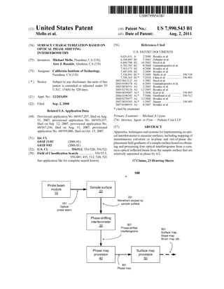
  • 1. 111111 1111111111111111111111111111111111111111111111111111111111111 c12) United States Patent Mello et al. (54) SURFACE CHARACTERIZATION BASED ON OPTICAL PHASE SHIFTING INTERFEROMETRY (75) Inventors: Michael Mello, Pasadena, CA (US); Ares J. Rosakis, Altadena, CA (US) (73) Assignee: California Institute of Technology, Pasadena, CA (US) ( *) Notice: Subject to any disclaimer, the term ofthis patent is extended or adjusted under 35 U.S.C. 154(b) by 320 days. (21) Appl. No.: 12/203,050 (22) Filed: Sep.2,2008 Related U.S. Application Data (60) Provisional application No. 60/967,297, filed on Aug. 31, 2007, provisional application No. 60/993,657, filed on Sep. 12, 2007, provisional application No. 60/967,296, filed on Aug. 31, 2007, provisional application No. 60/999,006, filed on Oct. 15, 2007. (51) Int. Cl. GOJB 11102 (2006.01) GOJB 9102 (2006.01) (52) U.S. Cl. ......................... 356/512; 356/520; 356/521 (58) Field of Classification Search ................. 356/35.5, 356/489,495,512,520,521 See application file for complete search history. Probe beam I Sample surface module 20 1Q US007990543B1 (10) Patent No.: US 7,990,543 Bl Aug. 2, 2011(45) Date of Patent: (56) References Cited U.S. PATENT DOCUMENTS 6,031,611 A 6,268,883 B1 6,469,788 B2 6,781,702 B2 7,363,173 B2 7,487,050 B2 7,538,891 B1 * 7,760,363 B2 * 2002/0012122 A1 2003/0106378 A1 2005/0030551 A1 2005/0278126 A1 2006/0039007 A1 * 2006/0146342 A1 * 2006/0276977 A1 2007/0019203 A1 * 2007/0180919 A1 * cited by examiner 212000 Rosakis et a!. 7/2001 Zehnder eta!. 10/2002 Boyd eta!. 8/2004 Giannakopoulos eta!. 4/2008 Rosakis et a!. 212009 Rosakis et a!. 5/2009 Mello eta!. ................... 356/520 7/2010 Chen eta!. .................... 356/491 112002 Boyd eta!. 6/2003 Giannakopoulos eta!. 2/2005 Rosakis et a!. 12/2005 Rosakis eta!. 2/2006 Kim et al...................... 356/495 7/2006 Doerband eta!. ............ 356/512 12/2006 Rosakis eta!. 112007 Jansen .......................... 356/495 8/2007 Rosakis et a!. Primary Examiner- Michael A Lyons (74) Attorney, Agent, or Firm- Perkins Coie LLP (57) ABSTRACT Apparatus, techniques and systems for implementing an opti- cal interferometerto measure surfaces, including mapping of instantaneous curvature or in-plane and out-of-plane dis- placement field gradients ofa sample surface basedonobtain- ing and processing four optical interferograms from a com- mon optical reflected beam from the sample surface that are relatively separated in phase by rri2. 17 Claims, 23 Drawing Sheets 100 101 ')Optical 201 Wavefront shaped by ~ sample surface probe beam Phase-shifting interferometer 30 I I 301 Phase-shifted interferograms 501 !~I Surface map; Slope map; Strain map; etc. ' )Phase map Surface map '----pr_o_~_eo_ss_o_r_ __, r····.___p_r_oc-5e_os_s_o_r----'~ - ..... 401 Phase map
  • 2. Probe beam m~d0ule J J 101 JOptical probe beam FIG. 1(a) - Sample surface 20 .~100 / 201 Wavefront shaped by ~ sample surface ~ Phase-shifting interferometer 30 301 Phase-shifted 1 interferograms I i~I I 'Phase map I pro~e;sor ~-------- ( 401 Phase map Surface map processor 50 501 Surface map; Slope map; Strain map; etc. )_.,. ~ 00 • ~ ~ ~ ~ =~ ~ ~ N~ N 0 ........ rFJ =-('D ('D ...... .... 0 ...... N (,H d rJl -....l c C =u.~ w =""""'
  • 3. FIG. 1(b) Phase-shifting interferometer 30 10-1~ laser 101 Optical probe beam11 Telescope Wavefront shaped by ""' sample surface or sample wavefront / Beam splitter .12. Sample surface 20 ~ 00 • ~ ~ ~ ~ =~ ~ ~ N~ N 0 ........ rFJ =-('D ('D ..... N 0 ..... N (.H d rJl -....l c C =u.~ w =""""'
  • 4. FIG. 1(c) 10-2- Phase-shifting interferometer Telescope .1Q I.____3_0------~~v ~201Wavefront shaped by sample surface or sample wavefront 101-1 101 i Mirror Optical .. 1± j probe beam '111!!1 "'>- X. i<:: ',~ I laser I 1 11 Polarizing 13 ' beam splitter Sample surface 101-2 w/ grating 22 ~ 00 • ~ ~ ~ ~ =~ ~ ~ N~ N 0 ........ rFJ =-('D ('D ..... (.H 0 ..... N (.H d rJl -....l c C =u.~ w =""""'
  • 5. FIG. 1(d) Sample surface 20 a x2 101 (Optical J .probe beam I I I I (12 : I I ~ 205 / Sheared wavefront .;/" L...............L.~ ·:···············v·························[/···············f······················~ x3 ../ ,/' _ ) ~I I b I , i~~~ ······· 201 Wavefrontshapedby G1-71 G2-72 sample surface or sample wavefront 10-1 ~, ',......... _1 01 201 ~ 00 • ~ ~ ~ ~ =~ ~ ~ N~ N 0 ........ rFJ =-('D ('D ..... .j;o. 0 ..... N (,H d rJl -....l c C =u.~ w =""""'
  • 6. FIG. 1(e) Sample surface w/ grating 22 a x2 101 / " - Optical j . probe beam ~ 205 ../ Sheared wavefront v-----j/r'~:=_t--· - I I x3 b a ' 201 _ ) Wavefront shaped by sample surface or sample wavefront 10-2 u2{!~ _/ : ~ a' :! 201 :'-----y----J:I I I 11 I I I G1-71 G2-72 ' 2la_______... ~ ·¥' • ~' •I A.+ ..c-r101 201 ~ 00 • ~ ~ ~ ~ =~ >=~ N~ N 0 ...... ...... rFJ =-('D ('D ...... Ul 0 ..... N (.H d rJl -....l c C =u.~ w =""""'
  • 7. Sample surface 20 or 22 ....... ..... 201 .. 2011 2012 sample wavefront~ @time tx • FIG. 2(a) ... .......Q) E . i=· ' 013 2014 ~/ 71 I ..... ..... ..... ..... ~30a Phase map processor . 40 72 ..... ..... ..... ..... 3011 -------------~ t1=0 3012 . -------------~ t2=.6.t ~ 301x Corresponding phase-shifted interferogram 3013 -------------~ t3=2.6.t 3014 -------------~ t4=3~t ' ~ 00 • ~ ~ ~ ~ =~ ~ ~ N~ N 0 ........ rFJ =-('D ('D ..... 0 0 ..... N (.H d rJl -....l c C =u.~ w =""""'
  • 8. U.S. Patent Aug. 2, 2011 Sheet 7 of23 US 7,990,543 Bl FIG. 2(b) /-200 Obtain a sample wavefront 0 20 + j=1 t=O, J (~) Induce a phase shift of the sample wavefront 2 ~j(tj)=~(tj)+U-1 )n/2 ~ 30 + Induce a lateral shear of the phase-shifted wavefront 2 d/dx1 or d/dx2 ~ 31 + Obtain a fringe pattern of the sheared wavefront 2 lj(tj)=lm(tj)+la(tj)COS~j(tj) ~ 32 + j=j+1; tj=U-1 )M A N~J>4 y I Output: ps11(t1), 12(t2), 13(h), 14(4) + Obtain the phase map ~(t1) 0assuming ~(t1)=~(t2)=~(t3)=~(4) 40
  • 9. Probe beam m~~ule v 101 Optical probe beam 501 Surface map; Slopemap; Strain map; etc. 1 -+--- FIG. 3 Sample surface 20 lr Wavefront replicator 60 Surface map processor 50 -300 ~ 201 601 Four copies of the .( sample wavefront ~ -__.. ... ... __.. Phase-shifting interferometer 35 ~ 351 Phase map ~--------1.____p_r-oc-4e-0s_s_o_r_ ___.I C01Phase map Phase-shifted interferograms ~ 00 • ~ ~ ~ ~ =~ ~ ~ N~ N 0 ........ rFJ =-('D ('D ..... QO 0 ..... N (.H d rJl -....l c C =u.~ w =""""'
  • 11. Wavefront replicator 60 FIG. 4(b) 6011 6012 6013 6014 r35 70 Copies of the sample wavefront 3511 3512 3513 3514 Phase map processor 40 _ Phase-shifted interferograms ~ 00 • ~ ~ ~ ~ =~ ~ ~ N~ N 0 ........ rFJ =-('D ('D ..... ....0 0 ..... N (.H d rJl -....l c C =u.~ w =""""'
  • 12. U.S. Patent Aug. 2, 2011 Sheet 11 of 23 US 7,990,543 Bl FIG. 4(c) -400 Obtain a sample wavefront ~0 + Obtain 4 copies of the sample wavefront 020 + Induce a relative phase shift for each copy of the wavefront 43 ~j(t)=~(t)+U-1 )n/2, where j=1-4 ___./ 5 + Induce a lateral shear for each of the phase-shifted wavefronts d/dx1 or d/dx2 36 ~ + Obtain a fringe pattern for each of the sheared wavefronts 437 lj(t)=lm(t)+la(t)cos~j(t), where j=1-4 ~ + I Output: ps11(t), 12(t), 13(t), 14(t) + Obtain the phase map ~(t) 040
  • 13. ( ·-~ 601 Copies of the sample wavefront FIG. 5(a) 72 Sheared P1 order sheared wave fronts. passed Filtering Lens .rStandard Ronchi grating )If -35 78 l Imaging Lens 76 ~ Filter Plane 80 CCD 351 Phase-shifted interferograms ~ 00 • ~ ~ ~ ~ =~ ~ ~ N~ N 0 ........ rFJ =-('D ('D ..... ....N 0 ..... N (.H d rJl -....l c C =u.~ w =""""'
  • 15. 62 64 csm7ongrating ') - -r.M"'/&"+/ ___..;:_--11<:0- .7'.,,,.. = -c:J• iEntrance pupil 201 sample wavefront FIG. 6 '----y-----l Telecentric Scan lens ~/~ -60-1 621 66) Telecentric Scan lens 68 Mosaic blazed grating arrangement Exit pupil I ff/////....~.. ~--~z ...,.,.,.,.,.,,,--??· 601 Four copies of the sample wavefront ~ 00 • ~ ~ ~ ~ =~ ~ ~ N~ N 0 ........ rFJ =-('D ('D ..... .....j;o. 0 ..... N (.H d rJl -....l c C =u.~ w =""""'
  • 18. 35-2 ~900 / 35-1 ,;® 60-1 '-_il_ !non-polarizing w~~~~~u ! ux, beam splitter j · 20 ~ gratmg 12 Blazed Telecentric Filter Telecentric ratings scan lens plane scan lens FIG. 9 Reflection/Transmission by specimen I I 10-1 beam reducer 20 ~ 00 • ~ ~ ~ ~ =~ ~ ~ N~ N 0 ........ rFJ =-('D ('D ..... ....-....l 0 ..... N (.H d rJl -....l c C =u.~ w =""""'
  • 19. 22 +1and -1 orders each split into four parallel beams using four-channel beam ~~· ..-1000 ......" X::; .,x2 j I x splitter (not depicted) .r 1 / ,.. :_2_ ... ~ .... _ I ,. ,..J:,....~~/ - .......;!- ..... ~ Q"~"/·p / ::> ·---l., /~ t ·rlf.:::::-..___~/.;:? x3--· . ~---j -........_._,-::./4 .~ +1 L~ns r 1.:''"·"'-, ..._ L________~·/'i<-~· e 'if, J ,. .. ' __ L:_1 • k / " polanzmg :..._f!-1'/w.~~~-~.,.<::i':* .- r• ' a beam splitter .,< ~+1 _;:;:~- .. . . - -. i>' ··<::::··w t. llil[ ·x ciX1 '~-' X<. , / ···!'-> '"'~·1';,";-,~<~t~"···"·iJl! I____ ,.. 4" -- v Specimen Nom1allydlffracted • .~... ~~--~* _..~·¥+ I-f '9h Speea Cameras X ...l' 3 beam splitter G:atings Filtering v_ Y ' ~ )fr~--"Cik~ (40 llnes/mm) lens Filler Field -1 c.~1 --<;r~i x 312 1.. Plane Lens ! i' ;---. . ,___ '/10-2 -..._, l·t '9h Speed Cameras 35-3 FIG. 10(a) ~ 00 • ~ ~ ~ ~ =~ ~ ~ N~ N 0 ........ rFJ =-('D ('D ..... ....QO 0 ..... N (.H d rJl -....l c C =u.~ w =""""'
  • 20. 22 "" .,. ~1050 'nto four parallel be ; ox2 rw'1 1beam ,. four-channe ' , USing . ted) ; (J / ; splitter (not deplc ; -.. ; , ax, __ _____ j High Speed ..-:1 /,...--......... 2Jr f('iJu, )(l +cose)-( i~u~)sillElf~ Camera 2.,. ,--- - l <'hi , x32 }t.------- -- 4>"' =) ax, ' . ~ .,./ .-··. / " --11 [;J' -1 ' ' - . ' "" ' ...'* - '· ' •,' " ' "-"'&/· " ·:·.; ......:if " I 1111 . ..... ... -1 0.v ·_. I' ·.~-:;7~x·~~-,<...::·.::;;·;·* 1111. @d·. +l ,." ~....'>;:.:;,;~..., .... ~ ~.<' --- " / . ".. ' - :~ " " " 4'1' ------ ' - -..~. ·''.· cted -fi?~... /C. •Specimen Normally dlffra "'t ' ·• :, ~ .,. ·• -~ gra1ing 1" order beams . Filtering D. - ":1~"c"'/~ x 3~1200lines/mm) CGS gratings lens Filter . imaging rizing ''""i :&::c;,,... (40 lines/mm) Plane Lens b~;~splitter L.~....1/ ' , High SpeedJ ) . (aul)sinel ~· Camera 1 1Q..2 2n (au, (I +cosE>J+ . 1 . '1rI>+ = l . (.1 I< u. 1 ;, d. FIG. 10(b) ~ 00 • ~ ~ ~ ~ =~ ~ ~ N~ N 0 ........ rFJ =-('D ('D ..... ....0 0 ..... N (.H d rJl -....l c C =u.~ w =""""'
  • 22. BLAZE ~ BLAZE FIG. 11(b) 831 821 Original 01 h order beams deviated Original 1st order beams / propagate parallel to the optic axis ~82 ~· Blaze direction Blaze direction ~ 00 • ~ ~ ~ ~ =~ ~ ~ J'J N 0 ........ rFJ =-('D ('D ..... N .... 0 ..... N (.H d rJl "'--...1 C C "'=u. ~ w =""""'
  • 23. "~ 60-3 ,. 601 92 621 62 --)> FIG. 12 beam deviation (8) ~ 00 • ~ ~ ~ ~ =~ ~ ~ N N 0 ........ rFJ =-('D ('D ..... N N 0 ..... N (.H d rJl -....l c C =u.~ w =""""'
  • 24. /-60-4/,. 104 104-1 ( 104-2 / 105-1 641 <P { Omax' I50-50 v c ) splitting ) 642 104-3 FIG. 13 /105 601 ----------- ) I 'I' ( 105-2 ~05-3 ~ 00 • ~ ~ ~ ~ =~ >=~ ~ N 0 ........ rFJ =-('D ('D ..... N (.H 0 ..... N (.H d rJl -....l c C =u.~ w =""""'
  • 25. US 7,990,543 Bl 1 SURFACE CHARACTERIZATION BASED ON OPTICAL PHASE SHIFTING INTERFEROMETRY PRIORITY CLAIMS This application claims the benefits of the following four U.S. patent applications: 1. U.S. Provisional Application No. 60/967,297 entitled "Compact diffraction grating based quad beam splitter arrangement for the creation offour parallel beams" and filed on Aug. 31, 2007, 2. U.S. Provisional Application No. 60/993,657 entitled "Compact diffraction grating based quad beam splitter arrangement for the creation offour parallel beams" and filed on Sep. 12, 2007, 3. U.S. Provisional Application No. 60/967,296 entitled "Concept for Spatial (instantaneous) phase shifting ofCoher- ent Gradient Sensor (CGS) interferometer" and filed on Aug. 31,2007,and 4. U.S. Provisional Application No. 60/999,006 entitled "Four Channel Spatial Phase Shifting Device and Wave Front Shearing Interferometer" and filed on Oct. 15, 2007. The disclosures ofthe above four U.S. patent applications are incorporated by reference as part of the specification of this application. FEDERALLY SPONSORED RESEARCH OR DEVELOPMENT The U.S. Government has certain rights in this invention pursuant to Grant No. DE-FG52-06NA26209-T-103505 awarded by Department of Energy and Grant No. N00014- 06-1-0730 awarded by Office ofNaval Research. BACKGROUND This application relates to optical sensing of surfaces, including optical measurements of surface slopes and other topographical properties ofsurfaces in flat panels, substrates, and wafers. 2 phase of the sample wavefront carries information on the sample surface addressed by the probe beam. The system includes an interferometer configured to simultaneously shift by rt/2 the relative phase of each copy of the sample wave- front. The interferometer causes interference of the four phase shifted copies of the sample wavefront with a corre- sponding reference wavefront. The interferometeralso simul- taneously generates four interferograms having a common phase term. The common phase term is the phase of the 10 sample wavefront. The system includes a phase map proces- sor to process the four simultaneously generated interfero- grams to obtain the common phase term. The system also includes a surface map processor to generate a map ofsurface 15 shape parameters of the sample surface. In yet another aspect, a method is described to include obtaining four spatially-separated copies ofan optical wave- front. The phase ofthe optical wavefront carries information on a sample surface. The method includes simultaneously 20 generating four interferograms ofthe four spatially-separated copies of the optical wavefront. The interferograms are rela- tively separated in phase by rt/2 and have a common phase term equal to the phase ofthe optical wavefront. The method also includes processing the generated four interferograms to 25 obtain the common phase term carrying information on a sample surface. In another aspect, an apparatus includes a sample holder to hold a sample under test. The apparatus also includes an optical probe module to direct coherent light to the sample 30 surface. The apparatus contains a first grating element includ- ing four gratings shifted laterally by a quarter pitch between adjacent gratings to shift by rt/2 the relative phase of four spatially separated copies of a sample wavefront that carries 35 information on the sample surface. The apparatus also includes a second grating element downstream from the first grating element having a uniform groove pattern and same pitch as the gratings of the first grating element. The second grating element shears the four phase shifted copies of the 40 sample wavefront. The apparatus contains an imaging com- ponent to capture four phase shifted shearing interferograms generated by the first and second grating elements. The appa- ratus includes a processor to manipulate the generated four Optical interferometry uses optical interference between two at least partially mutually coherent optical beams to obtain useful information carried by the optical interference patterns. For example, optical interferometry can be used for 45 optical sensing and optical interference patterns can be pro- cessed to extract information embedded in the wavefront ofat least one ofthe beams as an optical probe beam which inter- acts with a sample under measurement. interferograms to obtain information on the sample surface. The details of these and other aspects of the apparatus, techniques and systems for implementing an optical interfer- ometer to measure surfaces are set forth in the accompanying drawings, the description and the claims below. 50 SUMMARY This application describes, among others, apparatus, tech- niques and systems for implementing an optical interferom- eter to measure surfaces, including mapping of in-plane and 55 out-of-plane displacement field gradients ofa sample surface. In one aspect, a method for optically characterizing a sur- face is described to simultaneously obtain four optical inter- ferograms from a sample surface that are relatively separated in phase by rc/2. The method also includes processing the 60 obtained four optical interferograms to extract information on the sample surface. In another aspect, a system is described to contain a probe beam module to generate a coherent optical probe beam and to direct the probe beam to a sample surface. The system also 65 includes a wavefront replicator module configured to gener- ate four spatially separated copies ofa sample wavefront. The BRIEF DESCRIPTION OF DRAWINGS FIG. l(a) shows an exemplary system including a phase shifting interferometer for obtaining whole field mapping of various parameters of a sample surface. FIG. l(b) illustrates an implementation of a probe beam module. FIG. l(c) illustrates another implementation of a probe beam module. FIG. l(d) illustrates operations of a shearing interferom- eter including two shearing gratings. FIG. l(e) illustrates other operations ofa shearing interfer- ometer including two shearing gratings. FIG. 2(a) illustrates phase shifting operations ofa shearing interferometer including two shearing gratings. FIG. 2(b) shows an exemplary method based on phase shifting interferometry for obtaining whole field phase map- ping ofa sample surface.
  • 26. US 7,990,543 Bl 3 FIG. 3 shows an exemplary system including a real-time phase shifting interferometer for obtaining instantaneous whole field mapping of various parameters of a sample sur- face. FIG. 4(a) illustrates a diagram of a wavefront replicator module. FIG. 4(b) illustrates a diagram of a four channel shearing interferometer with integrated phase shifting capability. FIG. 4(c) shows an exemplary method based on real-time phase shifting interferometry for obtaining instantaneous whole field phase mapping of a sample surface. FIG. 5(a) illustrates an exemplary implementation ofa four channel shearing interferometer with integrated real-time phase shifting capability. FIG. S(b) illustrates exemplary components ofa four chan- nel shearing interferometer with integrated phase shifting capability. FIG. 6 illustrates an exemplary implementation ofa wave- front replicator module. FIG. 7 illustrates an exemplary implementation of a beam splitter element. FIG. 8 illustrates an exemplary implementation of a beam steering element. FIG. 9 illustrates an exemplary implementation ofa system including a real-time phase shifting interferometer forobtain- ing instantaneous whole field mapping ofvarious parameters of a sample surface. FIG. 10(a) illustrates an exemplary implementation of a system including two real-timephase shifting interferometers for obtaining instantaneous whole field mapping of various parameters of a sample surface. FIG. 10(b) illustrates another exemplary implementation of a system including a real-time phase shifting interferom- eter for obtaining instantaneous whole field mapping ofvari- ous parameters ofa sample surface. FIGS.ll(a) and ll(b) illustrate another exemplary imple- mentation of a wavefront replicator module. FIG. 12 illustrates portions of yet another exemplary implementation of a wavefront replicator module. FIG. 13 illustrates an exemplary implementation ofa com- pact wavefront replicator module. DETAILED DESCRIPTION In-plane displacements and out-of-plane displacements of a sample surface can be measured using various optical inter- ferometric techniques, including optical interferometric mea- surements based on lateral shearing techniques. The wave- front of a probe beam after reflection or diffraction of the surface ofa sample is distorted by in-plane displacements and out-of-plane displacements on the sample surface. To obtain a distribution or map of the out-of-plane and in-plane dis- placement field gradients corresponding to the sample sur- face, the phase distribution map ofthe distorted wavefront is determined. To quantifY the phase map corresponding to a sample surface ofinterest, a set ofat least three optical shear- ing interferograms ofthe distorted wavefront are obtained by a shearing interferometer. The shearing interferometer con- tains an element situated in the pathofthe distortedwavefront (or in the path of a reference wavefront for other types of phase shifting interferometers) which can introduce known phase shifts. By measuring the intensity pattern for each of the phase shifted interferograms, the phase map of the dis- torted wavefront can be obtained. The topographic profile of the surface or various out-of-plane and in-plane displacement maps can be obtained once the phase map is known. 4 The phase shifting element ofvarious phase shifting inter- ferometers can include a translation stage. The motion ofthe translation stage can introduce misalignments, misregistra- tions or vibrations which manifest as noise in the calculation of the phase map. Moreover, even if the noise caused by moving translation stages can be mitigated, the phase shifted interferograms acquired upon movement of a phase shifting element are taken in successive order (by definition). The set ofinterferograms acquired in this manner can be used in the 10 calculation ofthe phase map only assuming that the surface of the sample does not change on the time scale of successive excursions of the translation stage. Therefore, the succes- sively acquired phase shifted interferograms contribute only 15 to a time-averaged phase profile of the distorted wavefront, and are not representative of the instantaneous state of the sample surface. The techniques, apparatus and systems described in this application allow for obtaining simultaneous (instantaneous) 20 phase shifted interferograms ofthe distorted wavefront. Once a set of four interferograms are obtained in one shot, a true real-time phase map of the distorted wavefront can be obtained, in contrast to the time-averaged phase map that is obtained using other phase shifting interferometers. Upon 25 determining the real-time phase map of the distorted wave- front, many of the parameters specific to the surface can be obtained dynamically, such as for example, surface profile, out-of-plane and in-plane displacement field gradients corre- sponding to the sample surface, etc. For instance the surface 30 ofa flat panel display subject to vibrations can be monitored by acquiring successive sets of phase maps characteristic to the instantaneous surface shape of the vibrating flat panel display. The evolution ofthe surface map, or the out-of-plane and in-plane displacement field gradient maps corresponding 35 to the sample surface monitored in this marmer can be very useful for understanding the failure modes of flat panel dis- plays, during transport or under extreme dynamic conditions, such as on the battlefield. FIG. 1(a) illustrates diagrmatically a system 100 which 40 uses a phase shifting interferometer to obtain a profile (eleva- tion map), slope (out-of-plane distortions) and strain fields (in-plane distortions) of a sample surface. Each block ofthe diagram represents a functional module and can contain mul- tiple components as indicated in subsequent sections. Each 45 arrow connecting the diagram blocks represents the output of the prior block and the input ofthe subsequent block, respec- tively. The probe beam module 10 contains an optical source and beam steering components to direct the probe beam 101 to the 50 sample surface 20. In the interferometric examples described in this application, the probe beam 101 is coherent and colli- mated. Specific implementations of the probe beam module 10 are discussed below. The sample surface is represented by block 20. The probe 55 beam 101 produced by the probe beam module 10 impinges on the sample surface 20 at a predetermined angle. Further- more, the probe beam 101 can reach the sample surface 20 of interest directly, when the optical probe beam 101 is incident to the sample surface 20. In another implementation, the 60 optical probe beam 101 can be incident on the back of the sample, and then transmits through the bulk ofthe sample to reach the sample surface 20. Moreover, the sample surface 20 can be specular to reflect the incident optical probe beam 101 like a mirror. In another implementation, the sample surface 65 20 can contain a grating to diffract the incident optical probe beam 101. The wavefront ofthe reflected or diffracted beams 201 is distorted by the sample surface 20, thus containing
  • 27. US 7,990,543 Bl 5 information about the instantaneous profile or out-of-plane and in-plane deformations of the sample surface. FIG.1(b) shows an exemplary implementation ofthe opti- cal beam module 10 and the sample surface 20. A laser 11 emits a collimated coherent probe beam 101. The optical probe beam 101 is directedby a beam splitter 12 to the sample surface 20 at normal incidence. The specular surface of the sample surface 20 reflects the optical probe beam 101 and forms a wavefront shaped by the sample surface 201. The wavefront of the reflected beam 201 contains information 10 about the instantaneous profile or out-of-plane and in-plane deformations ofthe sample surface 20. The wavefront shaped 6 sample under measurement and the nature of the mechanics problems under investigation. The application of such tech- niques in deformation analysis often requires numerical dif- ferentiation of discretely-sampled displacement data which may introduce significant error magnification problems. In addition, many ofthese methods can be undesirably sensitive to rigid-body rotations and susceptible to ambient vibrations. Wavefront shearing interferometry is an optical measure- ment technique for performing optical differentiations of wavefront phase by using self-referencing common-path interference between two laterally sheared wavefronts. A typical optical shearing interferometer produces and inter- feres two spatially shifted replicas of the same, usually dis- by the sample surface 201 is also referred to as the distorted wavefront 201 or simply as the sample wavefront 201. A telescope 15 directs the wavefront shaped by the sample surface 201 into a phase shifting interferometer 30. The tele- scope 15 also matches the size ofthe distorted wavefront 201 to the entrance pupil of the phase shifting interferometer 30. 15 torted wavefront of an optical beam along a direction trans- verse to the direction of propagation of the wavefront. The interference between the spatially shifted and replicated wavefronts generates an interference pattern representing the spatial distribution of slopes in the wavefront. In effect, the shearing interferometry performs an optical differentiation of FIG. 1(c) shows another exemplary implementation ofthe 20 optical beam module 10 and the sample surface 20. The laser the wavefront and thus can be used to reduce the numerical differentiation of discretely-sampled displacement data and thus reduce errors associated with such numerical differen- 25 tiation. Another feature of optical shearing interferomety is 11 emits the collimated coherent probe beam 101. The optical probe beam 101 is split into linearly polarized probe beams 101-1 and 101-2 by a polarizing beam splitter 13. The polar- ization of the probe beams 101-1 and 101-2 are relatively orthogonal. Mirrors 14 direct the polarized probe beams 101-1 and 101-2 to the sample. The mirrors 14 are placed such that the optical path ofthe two probe beam arms are ofequal length, thus preserving the temporal coherence between probe beams 101-1 and 102-1. In this implementation, the 30 sample surface 22 contains a grating. The probe beams 101-1 and 101-2 are incident on the grating situated on the sample surface 22 such that the diffracted beams 201 are normal to measurement ofa deformation ofone point of the wavefront to another of the same wavefront separated by the shearing distance, i.e., the distance between the two interfering repli- the sample surface 22. The wavefront of the diffracted beam 35 201 is distorted and contains information about the instanta- cas of the same wavefront. In this sense, an optical shearing interferometer is a self referencing interferometer and thus provides insensitivity or immunity to vibrations and other perturbations present at the wafer or device under measure- ment. A shearing interferometer can be configured to produce a shearing interference pattern from either ofthe optical trans- mission of the probe beam through the surface or from the optical reflection ofthe probe beam by the surface. The shear- neous out-of-plane and in-plane deformations of the sample surface 20. In this implementation, the angle of incidence corresponds to a diffraction order +1 for probe beam 101-1 and -1 for probe beam 101-2. The angle ofincidence 8 obeys the grating relation: (1) The grating pitch on the sample surface is denoted d, and Ais the wavelength of the probe beam 101. In this exemplary implementation, the diffracted wavefronts 201 propagate along a common direction but do not interfere because the polarizations ofthe two diffracted wavefronts are orthogonal. Again the telescope 15 directs the wavefront shaped by the sample surface 201 into the phase shifting interferometer 30. The telescope 12 also matches the size ofthe distorted wave- front 201 to the entrance pupil ofthe phase shifting interfer- ometer 30. 40 ing interference pattern is then processed to obtain surface, slopes, curvatures and other surface topographical informa- tion. Examples of measurable surfaces include but are not limited to surfaces in various panels and plates, various sub- strates and wafers, integrated electronic circuits, integrated 45 optical devices, opto-electronic circuits, and micro-electro- mechanical systems (MEMS), flat panel display systems (e.g., LCD and plasma displays), photolithography masks, pellicles and reticles. Optical shearing interferometry can be implemented in various configurations, including a coherent 50 gradient sensing (CGS) systemusing optical gratings to cause the shearing of the wavefront (see, e.g., U.S. Pat. No. 6,031, 611 ), a radial shearinterferometers, wedge plate ina bi-lateral shearing interferometer (see, e.g., U.S. Pat. No. 5,710,631) and others. Returning to the implementation based on the shearing interferometer, the distorted wavefront 201 interferes with the newly created sheared wavefront to obtain a first interfero- gram 301. An intensity pattern of dark and bright fringes representing the first interferogram 301 is acquired inside the phase shifting interferometer 30. To obtain the phase map corresponding to the distorted wavefront 201, three other distinct interferograms 301 have to be acquired. To produce distinct interferograms, a phase shifting mechanism inside Returning to FIG.1(a), the wavefront shaped by the sample surface 201 is directedto the phase shifting interferometer 30. 55 The role ofthe phase shifting interferometer 30 is to combine the distorted wavefront 201 with a reference beam and to obtain phase shifted interferograms 301. In this application the phase shifting interferometer 30 can be a shearing inter- 60 ferometer. Shearing interferometry is a self-referenced inter- ferometric technique, i.e., a sheared duplicate ofthe distorted front itself is used to cause interference, as explained below. Other types of phase shifting interferometers use distinct reference beams which interfere with the distorted beam. 65 the phase shifting interferometer 30 successively induces controlled phase shifts of the distorted wavefront, for example rri2, Jt and 3rrl2. The suitability ofthese interferometric techniques for opti- cal measurements depends on the optical properties of the
  • 28. US 7,990,543 Bl 7 Before explaining the phase shifting technique, the process ofobtaining the shearing interferogram is revisited. Also the relationship between the phase map and the out-of-plane and in-plane deformations ofthe sample surface 20 is quantified. FIG. 1(d) illustrates how shearing elements inside the phase shifting interferometer 30 cause interference of the wavefront 201 shaped by the sample surface, when the dis- torted wavefront 201 is specularly reflected off the sample surface 20. A ray reflected normally from a point a on the 10 sample surface 20 is transmitted through a first grating (G1) 71 of the shearing interferometer 30. The transmitted ray is then diffracted by a second grating (G2) 72. A second ray reflected normally from a neighboring point b at a distance S on the specimen surface is diffracted by G1 71 and transmit- 15 ted through G2 72. Both rays then merge and propagate as a sheared wavefront 205 through the remainder of the phase shifting interferometer 30. Following this process, which can be extended to all points on the sample surface 20, two iden- tical and laterally sheared wavefronts 205 interfere to create a 20 fringe pattern 301 which corresponds to a displacement gra- dient map of the reflected optical wavefront 201. For the sake of clarity and without any loss of generality, the case of a normally reflected beam in the plane (x2, x3) 25 which is laterally sheared along the x2 direction, as depicted in FIG. 1(d), is considered first. Results of the derivation are later extended to the beam propagating in the plane (x2, x3) and to the wavefront shearing, parallel to the x1 direction. As depicted in FIG. 1(d), the lateral shearing distanceS is 30 equivalent to the physical distance between two arbitrary neighboring points a and b, located on the specimen surface. From a ray optics perspective, two rays of light which origi- nate at each ofthese points are merged after passing through the pair of parallel gratings in the phase shifting interferom- 35 eter 30. The interference problem is analyzedby modeling the changes in optical path length which result due to the dis- placements ofpoints a and b and the associated phase change at corresponding points on the laterally sheared interfering wavefronts. Since point a and point b represent arbitrary 40 points on the sample surface, the optical path length descrip- tions apply to any pair ofneighboring points on the specimen surface and the extension to full field solution naturally fol- lows. Neglecting all common path phase terms and coordinate 45 scaling effects introduced by the imaging optics, the two laterally sheared, interfering wavefronts may be modeled as plane waves and expressedina symmetric form inaccordance with the coordinate description contained in FIG. 1(d): 50 (2) (3) 55 Here, A represents the plane wave amplitudes, k=2n/A. is the wave number, x3 represents the propagation distance to the image plane, t represents time, and the phase factor ll.S(x1, x2+/-S2/2, t) represents changes in optical path length 60 induced by the displacements which evolve over time at each ofthe neighboring points a and b which are separated by the lateral shearing distance s2 along the x2 direction. 8 The symbol * denotes the complex conjugate operation, Ea and E6 represent the combining plane wave fields, and the optical constants of proportionality have been suppressed. Substituting for the interfering plane waves from (2) and (3) into (4) leads to the familiar two beam interference expression /(x1 , x2 , t) = (5) Ia +h +2~cos~[;~~(~s(x1 , x2 +~· r) -~s(x1, x2 - ~· r)] The terms Ia=EaEa and I6=E6 E6 represent the steady state background intensity ofeach interfering beam. Note that the time averaged intensity relation is expressed here as a limit due to the fact that the quantity <l> is actually a function ofthe optical information collected at neighboring points and can therefore only approximate the intensity at the mid point (x1 , x2 ) in the limit that the shearing distance s2 is made sufficiently small. The intensity of the resulting interfero- grams is modulated by a relative phase term . 2n: [ ( S2 ) ( S2 )]1'1'2,3)52 =JJm.- ~S XJ, x2 + -, t -~S x1, x2- -, t S2~0 A 2 2 (6) The relative phase term is proportional to the relative changes in optical length between neighboring points a and b on the specimen surface and where the symbolic notation IWa 3>52 where a=1,2 and ~=1,2 is used in order to denote the ~ave­ front shearing operation of the normally (xa,x3) wavefronts with respect to the x direction. The inset 10-1 of FIG. 1(d) depicts how the optical path lengths ofthe normally diffracted wavefronts are altered as an arbitrary point a on the specimen surface shifts to a new location a' in the normal direction. A similar operation occurs to the displacements at the neighboring point b located at coordinate Assuming that the optical path from the light source to the specimen is the same for every ray within an incident beam, the change of path length (ll.S) of a reflected ray at each neighboring point is given by ~~-~-l_:_:>_~_ij = 2u,(xJ, x2 + ~· r) (7) point a ~~-~-l_:_:>_~_ij = 2u,(xJ, x2- ~· r) (8) point b The interference pattern is derived by taking the time aver- aged intensity of the combined plane wave fields given by (4) Similar optical path length expressions apply for the (x1,x3) 65 beam of neighboring points which are laterally displaced in the x2 direction, and for pairs of neighboring points within beam, which are laterally displaced in the x1 direction. Sub-
  • 29. US 7,990,543 Bl 9 stituting the optical path length expressions (7-8) into (6) leads to an explicit form of the relative phase term given by (9) 5 10 sheared wavefront 205 through the remainder of the phase shifting interferometer 30. Following this process, which can be extended to all points on the sample surface 20, two iden- tical and laterally sheared wavefronts 205 interfere to create a fringe pattern 301 which corresponds to a displacement gra- dient map ofthe reflected optical wavefront 201. The intensity of the resulting interferograms is therefore modulated by relative differential displacements which take place between pairs of neighboring points on the specimen surface. Ifthe shearing distances is made to equal zero, then there are no optical path length differences between the inter- fering wavefronts and the interferometer is rendered com- pletely insensitive. On the other hand ifs is too large, the interferometer will respond to differential displacements across a broad characteristic length on the specimen surface and fail to accurately capture local displacement gradient behavior. It is ofinterest to express lateral shearing in the limit where s approaches zero, yet remains finite, in order to accu- rately capture displacement field gradients, i.e out-of-plane slope maps, as a function ofposition on the specimen surface. Multiplying and dividing EQ. 9 by s2/s2 can be used to obtain As depicted in FIG. 1(e), the lateral shearing distanceS is equivalent to the physical distance between two arbitrary neighboring points a and b, located on the specimen surface. 1 ° From a ray optics perspective, two rays oflight which origi- nate at each of these points are merged after passing through the pair of parallel gratings in the phase shifting interferom- eter 30. The interference problem is analyzedby modeling the 15 changes in optical path length which result due to the dis- placements ofpoints a and b and the associated phase change at corresponding points on the laterally sheared interfering wavefronts. Since point a and point b represent arbitrary points on the sample surface, the optical path length descrip- 20 tions apply to any pair ofneighboring points on the specimen surface and the extension to full field solution naturally fol- an equivalent derivative form of the interferometer output as 25 follows: (10) EQ. 10 symbolizes optical differentiation of the normally reflected (x2, x3) wavefronts with respect to the x2 direction. In practice, the actual interferometer phase output given in 30 EQ. 9 is scaled by the factor 1/s2 . 35 A similar lateral wavefront shearing operation can be applied to the spatial differentiation ofthe (x1, x3) beam pair along the same shearing direction x2. Also, lateral wavefront shearing ofeither reflected beam pair along the orthogonal x1 wavefront shearing direction can be considered. All four 40 combinations can be summarized in a compact form as fol- lows: (11) 45 EQ. 11 denotes spatial differentiation ofthe normally dif- fracted (xa, x3) wavefronts with respect to x~ direction, 50 where a=1,2 and ~=1,2. Equation (11) therefore represents a total of four possible phase maps which can be obtained through the optical differentiation of normally reflected wavefronts. The form ofEQ. 11 suggests that the out-of-plane displacement gradient maps may be achieved extracting 55 whole field phase information from each laterally sheared diffracted wavefront. Wavefront shearing along other off-axis directions can also be performed. Turning to FIG. 1(e), the interference ofthe distorted wave- front 201 after diffraction off the grating on the sample sur- 60 face 22 is revisited. A ray diffracted normally from a point a on the sample surface 22 is transmitted through a first grating (G1) 71 ofthe shearing interferometer 30. Thetransmittedray is then diffracted by a second grating (G2) 72. A second ray diffracted normally from a neighboring point b at a distance S 65 on the specimen surface is diffracted at G1 71 and transmitted through G2 72. Both rays then merge and propagate as a lows. The derivation ofEQ. 2-6 corresponding to the implemen- tation illustrated in FIG. 1(d) also applies to the probe beam implementation depicted in FIG. 1(e). Therefore in analogy to EQ. 6, the intensity ofthe resulting interferograms is modu- lated by a relative term given by (12) The relative phase term is proportional to the relative changes in optical length between neighboring points a and b on the specimen surface and where the symbolic notation IWa.3 >sfl where a=1,2 and ~=1,2 is used in order to denote the wave- front shearing operation of the normally diffracted (xa,x3) wavefronts with respect to the x13 direction. The inset 10-2 of FIG. 1(e) depicts how the optical path lengths ofthe normally diffracted wavefronts are altered as an arbitrary point a on the specimen surface shifts to a new location a' in the transverse direction and a" in the normal direction. A similar operation occurs to the displacements at the neighboring point b located at coordinate Assuming that the optical path from the light source to the specimen is the same for every ray within an incident beam, the change of path length (llS) of a reflected ray at each neighboring point is given by ~-~~~-:_:~~__I_j= (13) point a (14) point b
  • 30. US 7,990,543 Bl 11 The ±symbols correspond to the individual m=±1 diffracted orders which comprise the (x2, x3) beam pair. Similar optical path length expressions apply for the (xl, x3) beam pair with pairs of neighboring points which are laterally displaced in the x2 direction, and for pairs of neighboring points within either beam pair, which are laterally displaced in the x1 direc- tion. Substituting the optical path length expressions (13-14) into (12) leads to an explicit form of the relative phase term given by I'1';;,->,2 = (15) ,;ir;'0 ~{(u,(x1 , x2 + ~· r)- u3(x1 , x2 - ~· r))o + cos0) ± Again the± symbols correspond to the respective m=±1 dif- fracted orders and also reflect the fact that the symmetrically diffracted wavefronts experience equal and opposite phase changes in response to a given transverse displacement. The intensity of the resulting interferograms is therefore modulated by a linear combination of relative differential displacements which take place between pairs ofneighboring points on the specimen surface. As discussed above, it is of interest to perform lateral shearing in the limit where s approaches zero, yet remains finite, in order to accurately capture displacement field gradients, i.e out-of-plane slope maps and in-plane strain fields, as a function of position on the specimen surface. Multiplying and dividing EQ. 15 by s~/s~ leads to an equivalent derivative form of the interfer- ometer output as follows: I +/-) 2n:{(au3(x1 , x2 , t))<1>2,3 = T ax (1 + cos0) ± '2 2 (16) EQ. 16 expresses optical differentiation of the normally dif- fracted (uwu3 ) wavefronts with respect to the x13 direction where ~=1,2. In practice, the actual interferometer phase output IWa 3+i->s is scaled by the factor of, D Similar lateral wavefront shearing operation can be applied to the spatial differentiation of the (xl, x3) beam pair along the same shearing direction. Also, lateral wavefront shearing of either diffracted beam pair along the orthogonal x1 wave- front shearing direction can be considered. All four shearing combinations may be summarized in a compact form as fol- lows: I +/-) _~{(au3 (x1 , x2 , t)) . + <Pa.3 - A ax (1 + cos0) _ 'f3 f3 (17) 12 -continued = _1_ I'!'+/-)S[J a,3 sp EQ. 17 summarizes spatial differentiation of the normally diffracted (uwu3 ) wavefronts with respect to the x13 direction 10 where a=1,2 and ~=1,2. Equation (17) therefore represents a total of eight possible phase maps which can be obtained through the optical differentiation of normally diffracted wavefronts. The form of EQ. 17 suggests that decoupling of 15 the in-plane and out-of-plane displacement gradient terms may be achieved through the addition or subtraction of sym- metric m=±1 phase terms, provided that a suitable procedure is available for extracting whole field phase information from each laterally sheared diffracted wavefront. Wavefront shear- 20 ing along other off-axis directions can also be performed. Phase shifting techniques canbe used to extract whole field phase information contained within generated interference patterns. In quasi-static testing applications, phase shifting of the individual laterally sheared diffracted wavefronts and 25 their associated interferograms may be executed in a sequen- tial fashion. Under dynamic test conditions however, where the phase front evolves rapidly in time, instantaneous phase shifting schemes can be used to simultaneously capture all of the phase-shifted interferograms as expressed by EQs. 11 or 30 17 without any significant time lag between measurements. Several such dynamic phase shifting schemes are presentedin future sections of this application. Phase shifting may be implemented to progressively adjust the phase separation between the two shifted interfering 35 wavefronts which cycles or manipulates fringe position on the specimen's surface under measurement. In one imple- mentation, a shearing interferometer may be configured to obtain multiple phased images ofa patterned wafer's surface, for example at 0, 90, 180, and 270 degrees in phase. The phase 40 shifting method allows for the wavefront slope to be mea- sured by calculating the "relative phase" modulation at each pixel on a detector array that receives the interference pattern. The phase shifting method also allows for consistent inter- pretation of wavefront and specimen slope on a surface that 45 exhibits changing reflectivity, like those found on patterned wafers. On a patterned wafer surface, each pixel location on the specimen may reflect light with a varying degree ofinten- sity relative to other pixel locations. This may complicate the interpretation of any single shearing interferogram. The 50 phase shifting method in shearing interferometry can simul- taneously increase the accuracy of the slope resolution and allow for accurate interpretation of interferograms on pat- terned surfaces with a spatially varying optical reflectivity. This is possible inpart because the relative phase ofeachpixel 55 or location within the shearing interfering pattern rather than merely the variation in the fringe intensity is measured. One property of the shearing interferometry due to its self-referencing nature is that the resulting shearing interfer- ence pattern essentially measures the deviations from flatness 60 ofthe surface under measurement by using the surface itself as a reference surface. Such relative data on surface height or flatness may be useful in various applications where the height or flatness ofa surface is monitored or controlled. For example, in a chemical mechanical polishing (CMP) process 65 orother surface polishing processes, the relative height across the surface may be monitored to determine the effectiveness of the polishing process. A shearing interferometer may be
  • 31. US 7,990,543 Bl 13 used to monitor the surface flatness and the measurements may be used to dynamically control the polishing conditionof the polishing process in real time. In some implementations, the shearing distance between the transversely shifted wavefronts that interfere with each 5 other may be adjusted during the measurement process to improve the resolution and accuracy ofthe data. By capturing interferometric images of the surface at multiple increments ofshearing distances, it is possible to resolve features smaller than the effective pixel size ofthe camera or imaging sensing 10 array being used to sample the interferometric data. In addi- tion, as described later in this application, the use ofmultiple shearing distances enables the highly accurate calculation of the estimated surface topography or nanotopography from 15 the relative data by a geometric calculation rather than a standard numerical integration algorithm to compute the actual surface profile. The phase shifting operation of a shearing interferometer 30, including a phase shifting element based on two gratings, 20 is presented in the format ofa swim-lane diagram 3Oa in FIG. 2(a). The swim-lane diagram 30a depicts in the left lane the sample surface 20 (see FIGS.1b and 1d) orthe sample surface 22 including a grating (see FIGS. 1c and 1e). The swim-lane diagram 30a depicts in the right lane a phase map processor 25 40 (also depicted in FIG. 1a). The center lane of the swim- lane diagram 40a contains the shearing interferometer 30, including the shearing gratings 71 and 72. The time flows in the vertical direction, such that early times are depicted at the top, and later times at the bottom of the swim-lane diagram 30 30a. Therefore each horizontal level of the swim-lane dia- 14 fixed grating 72, such that the relative phase between the interferograms 3012 and 3011 induced by this translation equals n/2. Ifthe pitch ofthe gratings 71 and 72 is p, then the lateral shift which induces a phase shift ofn/2 is p/4. A full2n phase shift (which is equivalent to no phase shift) is induced ifthe grating 71 were translated by a full pitch p. Fractions of the phase period (2n) are obtained by translating the grating 71 over corresponding fractions of the full pitch p. In the implementation described in FIG. 2(a), the fractional phase shift is Jt/2, a quarter of2n, corresponding to a grating trans- lation of a quarter of the full pitch p. The time intervalll.t to produce the phase shift is finite (not zero) because it takes a finite amount of time to engage the translation stage, translate the grating 71, and disengage the translation stage. During the time interval between t1 and t2 the sample surface 20 (or 22) may have remained unchanged, under static testing conditions (say, on a vibration isolation table). But, under dynamic testing conditions (say, on a shaker table, etc.) the state ofthe sample surface 20 at time t1 may be different from the state of the sample surface 20 at time t2. Therefore, the wavefront 2012, that is being phase shifted and sheared at t2, may carry different information about the sample surface 20 at time t2 then the wavefront 2011 did at t1<t2. At time t3, a time intervalll.t later than t2, the grating 71 is once again translated relative to the fixed grating 72, such that the relative phase between the interferograms 3013 and 3012 is incremented by n/2. A lateral translation ofgrating 71 equal to p/4 causes again the desired relative phase shift ofJt/2. The wavefront 2013 is phase shifted and sheared at t3 to obtain the phase shifted interferogram 3013. Finally, at time t4, a time interval ll.t later than t3, the gram 30a represents an instant of time. The distorted wave- fronts 201x travel from the sample surface 20 (or 22), from left to right, to the phase shifting interferometer 30. The interferograms 301x produced by the phase shifting interfer- ometer 30 are being passed, from left to right, to the phase map processor 40. At time t1=0 a wavefront 2011 shaped by the sample sur- face is being sheared by the shearing interferometer 30. Note that the distorted wavefront 2011 contains information about the state ofthe sample surface 20 (or 22) at this time tl. Also, 35 grating 71 is once again translated relative to the fixed grating 72, such that the relative phase between the interferograms 3014 and 3013 is incremented by n/2. Again a lateral trans- lation ofgrating 71 equal top/4 is needed to cause the desired relative phase shift of Jt/2. The wavefront 2014 is phase 40 shifted and sheared at t4 to obtain the phase shifted interfero- gram 3014. at this initial time, the relative position ofthe two gratings 71 and 72 is set to a certain value. Once the interferogram 3011 has been acquired and passed to the phase map processor 40 45 for later processing, the phase shifting interferometer is ready to induce a control phase shift of the distorted wavefront. The relative position ofgratings 71 and 72 can be modified in the transverse plane defined by directions x1 and x2 while maintaining the spacing between the two gratings 71 and 72 50 along the x3 direction fixed. A positioning mechanism, such as a precise translation stage or a positioning transducer, can be used to implement this adjustment ofthe relative position between the gratings for phase shifting. At least one lateral position controller may be engaged to one ofthe two gratings 55 to cause the lateral change in position. Two lateral position controllers may be respectively engaged to the two gratings to cause the phase shift. In this implementation, the two gratings may be maintained to be parallel to each other with the fixed 60 spacing during the lateral movement. Multiple shearing inter- ference patterns with different lateral relative positions between the gratings can be obtained for further processing with phase extraction and unwrapping algorithms. Attimet2, a time intervalll.t later than tl, a wavefront2012 65 shaped by the sample surface is being sheared by the shearing interferometer 30. The grating 71 is translated relative to the The interferograms 301x acquired sequentially in the swim-lane diagram 30a of FIG. 2(a) can be summarized in the equation (18) The index j=1-4. The term Im represents an average (back- ground) intensity, while the factor Ia represents the modula- tion amplitude ofthe fringe pattern. As depicted in the swim- lane diagram 30a of FIG. 2(a), the phase <I>(x1, x2, tj) distribution which modulates the phase shifted interfero- grams Iixl, x2, tj) 301 has been acquired at four successive times. The techniques, apparatus and systems described later in this application allow for the simultaneous acquisition of four phase shifted interferograms Ij 301, such that the system of equations (18) can be solved for an instantaneous phase map 401 <I>(x1, x2, t), at timet. Returning to FIG. 1(a), the phase map 401 <I>(x1, x2, t) is obtained by the phase map processor 40. The system of four linear equations (18) has the following four unknowns: Ia, Im, sin <I> and cos <I>. The phase map 401 <I>(x1, x2, <t>) 401 is found in terms of the four previously acquired phase shifted interferograms Ij(x1, x2, tj) 301:
  • 32. US 7,990,543 Bl 15 (19) Note that because each phase shifted interferogram Ij(x1, x2, tj) 301 is acquired at a different time tj, the phase map 401 represents a temporal average<t> of the sample surface 20 during the time interval from t1 to t4. Finally, the obtained phase map 401 is further processed by a surface map processor 50. Once the phase-shifted interfero- grams Ij(x1, x2, tj) 301 have been unwrapped, the surface profile or the slope map and the strain map can be obtained by processing EQs. 11 and 17. The interpretation of raw slope maps and the derivation of curvature may be enhanced by statistically fitting a surface polynomial to the raw slope data. Statistical surface fits, including Zernicke polynomials and Legendre polynomials, may be applied to raw slope data derived from, for example, patterned wafers for the purpose of deriving topography (or nanotopography) and curvature data. The method 200 illustrated in FIG. 2(b) summarizes the process of temporal (or sequential) phase shifting shearing interferometry. At step 220, a wavefront shaped by the sample surface is obtained. It was shown in regard to FIGS.1(b)-1(e) that there are several ways to obtain the distorted wavefront, for example through reflection, transmission, or diffraction of the sample surface. A set offour interferograms is sequentially acquired during the next steps. Therefore, a looping counter j and a time counter tj are initialized next. 16 the four phase shifted interferograms. The following sections present techniques, apparatus and systems to enable real-time phase shifting measurements using a shearing interferometer. FIG. 3 illustrates diagrammatically a system 300 which 5 uses a phase shifting interferometer to obtain a real-time (one-shot) profile (elevation map), slope (out-of-plain distor- tions) and strain (in-plain distortions) of a sample surface. Each block ofthe diagram represents a functional module and can contain multiple components as indicated in subsequent 10 sections. Each arrow connecting the diagram blocks repre- sents the output ofthe prior block and the input ofthe subse- quent block, respectively. The front end ofsystem 300, namely the probe beam mod- ule 10 and the sample surface module 20 have been described 15 in detail with regard to system 100 presented in FIG. 1(a). Namely, the probe beam module 10 prepares a coherent and collimated probe beam 101. Block 20 represents the surface of the sample of interest. As shown in FIGS. 1(b-e), the sample surface can specularly reflect or diffract the probe 20 beam 101, depending on the sample surface preparation. The wavefront 201 shaped by the sample surface carries phase information that maps the shape, slope or strain ofthe sample surface. At the back end ofsystem 300, the phase map processor 40 25 receives phase shifted interferograms 351 from the phase shifting interferometer 35 and obtains the phase map 401 corresponding to the sample surface 20. The phase map cal- culation is based on the method described above and summa- rized in EQ. 19. Once the phase map 401 is obtained, the 30 surface map module 50 extracts information related to the profile or out-of-plane and in-plane displacements of the sample surface 20. This information can be presentedinterms of surface parameter maps 501, for example, surface profile At step 230, a phase shift ofJt/2 with respect to the previous distorted wavefront phase is induced by the phase shifting interferometer. It was shown in regard to FIG. 2(a) that a quadrature phase shift is obtained through a relative lateral 35 translation of a quarter pitch between the two shearing grat- ings ofthe shearing interferometer. map, slope map, strain map, etc. It was shown above that within the framework of system 100, the phase shifting interferometer 30 can produce one phase shifted interferogram 301 at a time. In contrast, the phase shifting interferometer 35 in system 300 generates four phase shifted interferograms 351 at one time instance (in one At step 231, a lateral shear ofthe phase shifted wavefront is induced by the shearing gratings, as shown in FIGS. 1(d)-(e). The orientation of the grating lines determine the shearing direction, namely along the x1 or x2 axes. At step 232 an interferogram of the sheared wavefront is obtained. The fringe pattern is modulated by the phase ofthe distorted wavefront at the time ofthe measurement. Note that steps 230-231 have been segregated for the sake ofclarity, but in fact they occur simultaneously. Namely, the relative lateral displacement ofthe two shearing gratings induces the desired phase shift. The relative distance between the two shearing gratings determines the lateral shear (differentiation of the wavefront shaped by the sample surface). Finally, the inter- ferogram is acquired for a certain relative position ofthe two shearing gratings. To return to the beginning ofthe loop, at node A, the loop counter is initialized. Also the time counter is incremented by a time intervalll.t corresponding to the time needed to trans- late laterally one ofthe shearing gratings. The relative lateral translation determines the success of the subsequent phase shifting step 230. At the end of the loop, at output step 235, the set of four acquired interferograms is passed to the phase map compu- tation module. At step 240 the phase map corresponding to the wavefront shaped by the sample surface is obtained using EQ. 19. The calculation of the phase map is based on the assumption that the sample surface does not change on the time scale 3ll.t that it takes for subsequent phase shifts to occur. Equivalently, the phase map corresponds to a sample surface shape time-averaged over the time required to acquire 40 shot). The operation principle of the instantaneous phase shifting interferometry and the optical components which make the technique possible are described below. A system module relied upon in the operation of system 300 is a wavefront replicator module 60. The role of the 45 wavefront replicator module 60 is to receive the wavefront 201 shaped by the sample surface and to generate four iden- tical copies 601 of the wavefront. FIG. 4(a) shows a high level diagram of the wavefront replicator module 60. A detailed description ofthe wavefront 50 replicator module 60 is presented in regard to FIGS. 6-8. Returning to FIG. 4(a), the input of the wavefront replicator module 60 is the wavefront 201 shaped by the sample surface, and the output of the wavefront replicator module 60 is a set of four copies 6011-6014 of the wavefront shaped by the 55 sample surface. The wavefront replicator module 60 includes a first optical element 62 configured to split the incoming wavefront 201 shaped by the sample surface into four wave- fronts. The incoming wavefront 201 shaped by the sample surface enters the wavefront replicator module 60 parallel to 60 the optical axis. The resulting four wavefronts emerging from the first optical element 62 diverge from the optical axis. A second optical element 68 downstream from the first optical element 62 is configured to capture the diverging wavefronts. Further, the second optical element directs the four copies 65 6011-6014 of the wavefront to the output of the wavefront replicator module 60 along a direction parallel to the optical aXIS.
  • 33. US 7,990,543 Bl 17 FIG. 4(b) shows a high level diagram ofthe shearing phase shifting interferometer 35. A detailed description ofthe shear- ing phase shifting interferometer 35 is presented in regard to FIGS. 5(a)-(b). Returning to FIG. 4(b), the input ofthe shear- ing phase shifting interferometer 35 is the set of four copies 5 6011-6014 of the wavefront shaped by the sample surface, and the output of the shearing phase shifting interferometer 35 is a set of four real-time phase shifted interferograms 3511-3514. The shearing phase shifting interferometer 35 includes a phase shifting pair of optical elements 70 and 72. 10 The first optical element 70 includes a custom grating which includes four spatially distinct areas. Each area is configured to capture one (and only one) ofthe four copies 6011-6014 of the wavefront shaped by the sample surface. Furthermore, 15 each of the areas is configured to induce a quadrature phase shift to the respective incident copy 601 of the wavefront relative to the other wavefronts. The relative phase shifts are imparted simultaneously to all four copies 6011-6014 of the wavefront shaped by the sample surface. The four phase 20 shifted wavefronts traverse the grating 72 downstream from the optical element 70. Thus the four phase shifted wavefronts are sheared by the grating 72 to obtain four real-time phase shifted interferograms 3511-3514. FIG. 4(c) presents a method 400 to operate the system 300 25 illustrated in FIG. 3. The method 400 describes the acquisi- tion of real-time (one shot) phase shifted interferograms to obtain the instantaneous phase map corresponding to a sample surface. Once the instantaneous phase map is avail- able, multiple surface parameter maps can be extracted, such 30 as surface profile map, out-of-plane and in-plane displace- ment maps, etc. 18 relative lateral position between areas of the two shearing elements induces the desired set of phase shifts. The relative distance between the two shearing elements determines the lateral shear (differentiation of the wavefront shaped by the sample surface). Finally, the interferograms are acquired as the four copies ofthe wavefront shaped by the sample surface traverses the two shearing elements. At output step 438, the set offour acquired real-time inter- ferograms is passed to the phase map computationmodule. At step 440 the phase map corresponding to the wavefront shaped by the sample surface is obtained by solving the system ofequations 21. The four unknowns are Ia, Im, sin <I> and cos <I>. The phase map <I>(x1, x2, t) 401 is found in terms of the four simultaneously acquired phase shifted interfero- grams Ij(x1, x2, t). The four real-time phase shifted interfero- grams determine the phase map based on the formula: (22) Because the phase shifted interferograms Ij(x1, x2, t) have been acquired at the same time t, the phase map corresponds to the shape of the sample surface 20 at the given time t. In contrast, the phase map obtained through successive phase shifting, using system 100 and summarized in EQ. 19, repre- sents a time-averaged state of the sample surface. The following sections present various implementation of system 300 and method 400 to enable real-time phase shifting measurements. Forthe remainder ofthis application, the term real-time phase shifting is used interchangeably with one- shot phase shifting or spatial phase shifting. FIG. 5(a) illustrates schematically a shearing interferom- At step 410, a wavefront shaped by the sample surface is obtained. It was shown in regard to FIGS. 1(b)-1(e) that there are several ways to obtain the distorted wavefront, for example through reflection or diffraction of the sample sur- face. At step 420, four copies of the wavefront shaped by the sample surface are obtained. The availability ofthe four cop- ies allows for the simultaneous phase shifting ofthe original wavefront shaped by the sample surface. 35 eter 35 configured to perform real-time phase shifting. The implementation shown in FIG. 5(a) is only one ofmany other types of real-time phase shifting interferometers that can be used to operate the system 300 in FIG. 3. Examples of other interferometric techniques which could be configured for real At step 435, relative phase shifts ofrc/2 with respect to each other, for each copy of the distorted wavefront phase, are induced simultaneously. 7r <l>j(XJ, X2, t) = <l>(XJ, X2, t) + (j -1)2 (20) The index j=1-4. Note that each of the four shifted phases corresponds to the same time t. At step 436, a lateral shear ofthe four phase shifted wave- fronts is simultaneously induced by the shearing gratings. The orientation of the grating lines determine the shearing direction, namely along the x1 or x2 axes. At step 437 four fringe pattern of the sheared wavefronts are obtained. The interferograms are modulated by the phase of the distorted wavefront at the time of the measurement. (21) The indexj=1-4. Once again, each of the four shifted inter- ferograms corresponds to the same time t. Note that steps 435-437 have been separated for the sake of clarity, but in fact they occur simultaneously. Namely, the 40 time operation are Twyman-Green or Moire interferometers. In one exemplary implementation, the optical module 35 presented in FIG. 5(a) is a four-channel shearing interferom- eter with integrated spatial phase shifting capability. The interferometer35 illustrated in FIG. 5(a) includes phase shift- 45 ing elements, shearing elements, spatial filtering elements and imaging elements, as described below. The four-channel shearing interferometer with integrated spatial phase shifting capability 35 receives four copies 6011- 6014 of the wavefront shaped by the sample surface from a 50 wavefront replicator module 60. Several implementations of the wavefront replication module 60 are described in later sections. The optical element 70 at the input of the four- channel shearing interferometer with integrated spatial phase shifting capability 35 includes four Ronchi gratings arranged 55 in a square mosaic arrangement as shown in greater detail in FIG. 5(b). The gratings 702-705 or 707-710 in each adjacent quadrant of the mosaic configurations 701 or 706 are out of step by a distance equal to 1/4 of the Ronchi grating's fundamental 60 pitch. As discussed previously, the quarter pitch translation between adjacent gratings results in a rt/2 relative phase shift between the four copies 6011-6014 of the wavefront shaped by the sample surface. The four gratings can be unattached, but supported in the assemblies 701 or respectively 706 in 65 FIG. 5(b). Furthermore, the four gratings can be integrated into a component 701 or a component 706 (in contrast to the respective assemblies of unattached gratings). The orienta-
  • 34. US 7,990,543 Bl 19 tion 701 or 706 ofthe optical element 70 depends on whether the distribution of the incoming four beams 601 is a square (701) or a diamond (702) with respect to the optical axis. The second optical element 72 placed downstream from the first optical element 70 is a Ronchi grating. The ruling of 5 the second Ronchi grating 72 is uniform, with the same fun- damental pitch as the Ronchi gratings of element 70. The orientation 721 or 722 of the second optical element 72 matches the respective orientation 701 or 706 of the first optical element 70. 10 The four copies 6011-6014 ofthe wavefront shaped by the sample surface are directed to intercept a specific quadrant of element 70. The Ronchi grating which is part ofthat quadrant diffracts the respective copy 601 ofthe wavefront. Wavefront shearing takes place once the diffracted beams that emerge 15 from element 70 are re-diffracted by grating 72. Returning to FIG. S(a), the four sheared 1st order beams that emerge from grating 72 are focused by a filtering lens 74 and passed through a small hole in an opaque screen 76 that acts as a filter plane. Thus, other unwanted diffraction orders 20 created by the tandem gratings 70 and 72 are blocked out by the spatial filtering elements 74 and 76. Each sheared beam is then imaged to a specific quadrant of a camera sensor 80 by an imaging lens 78. The resulting interference patterns 3511-3514 exhibit a relative phase shift 25 of rc/2 radians due to the lj4 pitch offset between the gratings 20 project the resulting diffraction pattern 621 into a rectangular array about the optical (z) axis. Numerous diffraction orders associated with the fundamental grating pitch (p) arise in accordance with the general grating equation given by (23) The order of diffraction m (0, +1-1, +1-2, ... ) related to a specific diffraction order of interest, and X represents the laserwavelength. The four symmetrically orienteddiffraction orders 621 depicted in FIG. 7 represent the primary beams of interest. The combination of 532 nm laser wavelength and a diffraction grating line pair frequency of600 line/mm results in a 1st order diffraction angle 8=19°. The 2D grating 62 can be tuned to maximize the amount of energy that is diffracted into m=+/-1 orders while balancing a nearly equal intensity distribution between these beams. First order beams have been generated which posses 10% of the incident beam intensity (collectively equal to 40% ofthe original intensity). Two aspects regarding the use ofa 2D transmission grating as a beam splitter in the wavefront replicator module 60-1 are addressed below. The first effect is the presence of the unavoidable Oth order beam along with all of the higher diffraction orders that are generatedby the 2D grating. Theses beams are unwanted from the perspective of the overall spa- in each adjacent quadrant of element 70 with respect to the constant uninterrupted pitch ofgrating 72. In another imple- mentation the four phase-shifted interferograms 351 may be captured by four separate cameras. 30 tial phase shifting objective because the unwantedbeams may interfere with the 1st order beams. Suppression of undesired diffraction orders is achieved through the implementation of a spatial filtering arrangement, which is addressed next. The acquired interferograms 351 are stripped into four subset images by the camera 80, then post processed by modules 50 and 60 ofthe system 300, as shown in FIG. 3. As discussed previously, the post-processing calculation includes a four-step rc/2 phase shifting algorithm summarized 35 by EQ. 22, to yield whole field plots of surface slope and strain fields, in accordance with EQs. 11 and 17. The second effect concerns a one-dimensional (anamor- phic) reduction of the beam diameter that results along the direction running parallel to the plane of diffraction. The anamorphic reduction of a diffracted beam diameter is illus- trated in the inset 620 of FIG. 7. The ratio of the diffracted The next section provides a detailed description ofa wave- beam 621 diameter to the original beam 201 diameter is given front replicator module 60 used to generate four copies 601 of the original wavefront and to direct them to the four-channel 40 by shearing interferometer 35. The wavefront replicator module 60 includes beam splitting elements, spatial filtering and imaging elements, and beam steering elements, as described below. FIG. 6 illustrates an exemplary implementation of the 45 wavefront replicator module 60-1 [60]. A nominally colli- mated beam probe beam 101 is diffracted, reflected, or trans- mitted by a test specimen 20, and the wavefront 201 shaped D' m =-=cos() (24) D In the case of a 600 line/mm grating 62 and a 532 nm laser wavelength, the anamorphic effect results in a 1st order beam 621 diameter which has shrunk to -95% ofthe incident beam 201 diameter. Each of the four primary 1st order beams will thus experience a similar reduction in beam diameter along a uniquely different direction lying parallel to its respective diffraction plane. The anamorphic effect, ifunaccounted for, introduces pixel misregistration between the four phase shifted fringe patterns 351 when combined together to solve by the sample surface is directedtowards the entrance pupil of the wavefront replicator module 60-1 [60] parallel to the 50 optical axis. In another exemplary implementation, before reaching the wavefront replicator module 60-1 [60], the wavefront 201 shaped by the sample surface is passed through a telescope in order to reduce the overall beam diam- eter. 55 for the phase front using EQ. 22. As discussed below, the design of the wavefront replicator 60 mitigates the anamor- phic effect. Namely the anamorphic effect is precisely nulli- fied (reversed) with the introduction ofa mosaic blazed grat- ing arrangement 68, which is used as the final beam steering A two dimensional (2D) or crossed line transmission grat- ing 62 situated at the entrance pupil ofthe wavefront replica- tor module 60-1 [60] diffracts the incident beam 201 to create four equal intensity 1st order diffracted beams. FIG. 7 shows a more detailed diagram of the 2D grating 62 and the four copies ofthe diffracted wavefront 621, which carry identical information about the specimen's state of deformation. A normally incident and nominally collimated beam of light 201 emerging from a test specimen 20 is diffracted into a symmetric array of sharp diffraction orders using the 2D transmission grating 62. As shown in FIG. 7, the grating 620 is oriented at 45deg with respect to the x-y axes in order to 60 element in the four-charmel design, as discussed below. Returning to FIG. 6, the elimination of the unwanted dif- fraction orders is addressed first. The four 1st order beams 621 are focused by a telecentric f-theta lens 64 and passed through small holes in an opaque screen 65 situated at the 65 focal plane. The opaque screen blocks the Oth order beam as shown in addition to any other unwanted diffraction orders generated by the 2D grating 62.
  • 35. US 7,990,543 Bl 21 22 The separation distance between the focused beams at the rear focal plane 65 is given by o=f*tan 8, where f is the effective focal length ofthe scan lens and 8 is the diffraction angle. Commercially available telecentric scan lenses can be used for this focusing application since they are designed to deliver diffraction limited performance at the 532 nm laser wavelength in a nearly identical optical configuration. For example, a telecentric scan lens, with a focal length f=100 mm and an overall scanning range of +1-22° accommodates the anticipated 1st order diffraction angles 8=+/-18° while the nominal focal length (f=100 mm) induces a physical separation ofo=34 mm between the focused O'h and 1st order beams at the filter plane. The lens 64 also serves as a low pass filter because the lens 64 cannot accept any higher order beams whose diffraction angles exceed the scanning angle envelope. the anamorphic reduction (see EQ. 24) that is introduced by the 2D transmission grating 62. It is this feature that distin- guishes the use of blazed gratings as the final beam steering element 68 in the proposed design ofthe wavefront replicator module 60, as opposed to beam steering elements based on wedge prisms. In the next sections it is shown that a mosaic assembly ofwedge prisms, while able to efficiently steer the four beams back along the optical axis, cannot completely compensate for the anamorphic reduction unless combined 10 with an additional set ofcompensating set ofprisms resulting in a more complex design. The side views ofthe beam steering element 680 in FIG. 8 emphasize the manner in which two diagonally opposed A 2nd identical telecentric lens 66 then re-collimates the beams 621 and directs them to intersect at the exit pupil as shown in FIG. 6. Note that only two ofthe four beams 621 are depicted by the two-dimensional figure. The remaining two beams, diffracted within the y'-z plane lying normal to the plane ofthe figure, are processed by the lens 66 in an identical manner. The four beams intersect at the exit pupil as shown and proceed to deviate from each other with increased dis- tance along the optical axis. The beams are allowed to propa- gate out to a distance ll.m beyond the exit pupil, at which point the beams cease to overlap. 15 blazed gratings in a mosaic arrangement each diffract their respective incident beams 621. The corresponding 1st order beams are transmitted with high diffraction efficiency along the optical axis as shown, while the remaining weaker dif- fraction orders are deviated away from the axis in accordance 20 with the general grating equation. Any ofthese weaker orders (including the unwanted O'h order) that manage to reach the shearing interferometer 35 are blocked by the spatial filter 74-76 which is part of the shearing interferometer 35. Blazed gratings are chosen for the beam steering element 25 68 since such gratings are designed to maximize the amount oflight that is diffracted into the m=-1 order beam by virtue of a carefully engineered saw tooth groove profile which significantly enhances the diffraction efficiency. Commer- D .6.m=--- {2cos8 (25) 30 cially available blazed gratings exhibit a diffraction efficiency exceeding 50% for each polarization state at a wavelength of 532 nm. A total of four diffraction orders thus emerge from the mosaic arrangement of the beam steering element 62 as four At or beyond the distance ll.m from the exit pupil, the four beams 621 encounter an optical element 68. The optical ele- ment 68 includes a set of four blazed transmission gratings arranged in a square mosaic configuration. Each beam inter- cepts a specific quadrant ofthe arrangement whereupon it is once again diffracted. Four transmitted 1st order beams 601 emerge parallel to the optical axis in a closely packed con- figuration and propagate to the four-channel shearing inter- ferometer 35. 35 closely spaced light beams 601. The spacing between the emerging beams 601 may be adjusted by perturbing the posi- tion of the mosaic assembly with respect to the exit pupil of the 2nd telecentric lens 66, as shown in FIG. 6. The beams representing the four copies 6011-6014 of the wavefront 40 shaped by the sample surface propagate towards the input of the four-channel shearing interferometer with integrated spa- tial phase shifting capability 35. In the following sections ofthis application several imple- mentations of the system 300 illustrated in FIG. 3 are 45 described. A schematic representation of the mosaic blazed grating element 68 is depicted in FIG. 8. In this exemplary imple- mentation, the beam steering element 68 includes four ruled gratings on a single monolithic square glass substrate. In another exemplary implementation, the beam steering ele- ment 68 includes four individual blazed gratings that are mechanically positioned in a square assembly. The latter sin- gulated grating implementation enables independent posi- 50 tioning between the respective gratings. These additional degrees of freedom may accommodate for any mis-orienta- tions of the input beams 201. Each quadrant of the beam steering element 68 includes a blazed grating having its grooves inclined at an angle of 45° 55 with respect to thex andy-axes, as shown in FIG. 8.Agrating frequency of 600 line/mm, which matches the grating fre- quency ofthe beam splitting element 62, is used to generate a 1st order beam that propagates along the optical axis. The blazed angle directions are oriented as shown in the side view 60 of the beam steering element 680. This orientation of the blazed angles enables efficient diffraction of each incident light beam within its respective plane of incidence. As discussed above, an added benefit that results from the use of gratings as the final beam steering element 68 is the 65 anamorphic expansion that these gratings introduce. The anamorphic expansion identically compensates for (reverses) FIG. 9 illustrates schematically portions of a real-time phase shifting interferometric system 900. The proposed sys- tem 900 can be used in either static or dynamic testing appli- cations whenever it is necessary to simultaneously obtain both spatial derivatives of the optical wavefront. The system 900 includes an optical probe beam module 10-1 described in detail in regard to FIG. 1(b). The normally reflected or transmitted wavefront is shaped by the sample surface 20. The wavefront that emerges from the specimen surface 20 is split into four copies using a wavefront replicator module 60, described in detail in regard to FIGS. 6-8. A non-polarizing beam splitter 12, placed just after the wave- front replicator module 60, splits the four emerging parallel beams into two separate beam trains. Each train of beams is then directed to a separate four- channel shearing interferometer with integrated spatial phase shifting capability 35. Thus, the system 900 can simulta- neously perform optical differentiation of the wavefront along the two primary coordinate directions as indicated in FIG. 9. Namely, the first four-channel shearing interferometer with integrated spatial phase shifting capability 35-1 per- forms shearing along the x1 coordinate, while the second
  • 36. US 7,990,543 Bl 23 four-channel shearing interferometer with integrated spatial phase shifting capability 35-2 performs shearing along the x2 coordinate. 24 these optical interference techniques, their respective modes of operation, and the associated whole field variable that results from the measurement of optical path difference through the use of phase shifting interferometry. TABLE 1 Optical interference techniques amenable to four-channel spatial PSI, modes operation and associated field variables FIGS.10(a)-(b) illustrate how systems 1000 and 1050 use orthogonally polarized probe beams for simultaneous optical differentiation of the +1 and -1 normally diffracted beams. Each of the systems 1000 and 1050 uses two four-channel shearing interferometers with integrated spatial phase shift- ing capability 35 and can be used in either static or dynamic testing applications to simultaneously obtain both spatial derivatives of the optical wavefronts. 10 INTERFERENCE FIG. 10(a) depicts system 1000 that enables simultaneous optical differentiation ofthe +1 and -1 diffracted wavefronts along two independent coordinate directions. Optical probe beam module 10-2 provides two superimposed wavefronts 15 that emerge from the specimen grating 22. The two superim- posed wavefronts are rendered mutually incoherent by virtue of their orthogonal polarization states. Both wavefronts are then split into four copies using the wavefrontreplicatormodule 60 (not showninFIG.10(a), but 20 described in detail in regard to FIGS. 6-8). A non-polarizing beam splitter 12, placed just after the wavefront replicator module 60, splits the two sets of beams into two separate beam trains (as illustrated in FIG. 9). Each beam train is then directed to a separate four-channel 25 shearing interferometers with integrated spatial phase shift- ing capability 35-3 and 35-4. A polarizing beam splitter is placed after the final imaging lens, inside each real-time interferometer 35-3 and 35-4. The polarizing beam splitter is used to separate the sheared+1and -1 diffracted orders. Four 30 cameras are used to acquire both pairs of complementary fringe patterns for each arm of the system 1000. Because of the real-time capability ofthe four-channel shearing interfer- ometers with integrated spatial phase shifting, a set of four instantaneous phase shifted interferograms can be acquired in 35 one shot for eachcamera. That translates into a total ofsixteen phase shifted interferograms produced in one shot by the system 1050. This large set of real-time phase shifted inter- ferograms allows for the calculation of four simultaneous phase maps corresponding to various sample surface param- 40 eters, such as surface slopes and surface strains. Thus, system 1000 enables real-time monitoring of the sample surface 22 (for example a flat panel display) during stress tests, vibration tests or other dynamic durability tests that are being per- formed during the design and verification phase ofthe prod- 45 uct life cycle. FIG. 10(b) depicts a system 1050 that may be used in cases when optical differentiation of the diffracted wavefronts is provided along one coordinate direction. In this case both diffraction orders are simultaneously processed by the four- 50 channel shearing interferometer with integrated spatial phase shifting capability 35-5. The sheared (mutually incoherent) +1 and -1 diffracted orders are finally separated by a polar- izing beam splitter situatedjustbeyond the imaging lens. Two cameras are used to acquire the pair ofcomplementary fringe 55 patterns. The wavefront replication techniques described in this application can also be used to enable four-step rc/2 spatial phase shifting schemes for other interferometer arrangements such as moire interferometers, Twyman-Green interferom- 60 eters, and laser based Photo-elasticity. Other spatial (or real- time) phase shifting interferometry techniques devised for the interference techniques enumerated above rely upon a unique combination of polarizing optics to induce the proper phase shift. The four-channel beam splitting arrangement described 65 in this application can be integrated to work with any of the techniques mentioned above. Table 1 provides a summary of TECHNIQUE Coherent Gradient Sensor (CGS) Coherent Gradient Sensor (CGS) Coherent Gradient Sensor (CGS) MODE Diffraction Reflection FIELD VARIABLE surface slopes/strain fields au3 aui -a i = 1, 2; -ai = 1, 2; j = 1, 2 Xj Xj surface slope: au, .= 1 2 axj J , Transmission refractive index gradients: stress/fluid presure gradients aa- ap -au i=1,2 j=1,2;-a i=1,2 Xj Xj MoinS interferometer Diffraction in-plane displ.: u,(x1, X2o t); i = 1, 2 out-of-plane displ.: u3 (xlo x2 , t)Twyman-Green interferometer Twyman-Green interferometer Photo-elasticity Reflection Transmission Transmission index ofrefraction & thk. change: stress/fluid pressure ou(xlo x2 , t); p(x1o x2 , t) shear stress: 2 'tmax = 0 1 -02 = N F0 /h An exemplary integration of the wavefront replication techniques described above with a Twyman-Green interfer- ometer in reflection mode is explained here. Returning to system 300 in FIG. 3, a portion ofthe optical probe beam 101 is split before reaching the sample surface into a reference beam, for example, using a non-polarizing beam splitter 12. The reference beam is directed to a second wavefront repli- cator 60 to generate four spatially separated copies of the reference beam. The second wavefront replicator 60 can be implemented as described with respect to FIGS. 6-8, or other implementations presented later in reference to FIGS. 11-13. Returning to FIG. 3, the four copies ofthe reference beam generated by the second wavefront replicator 60 are directed to the phase shifting interferometer 35. There are several ways for the set of four copies of the reference beams to interfere inside a Twyman-Green interferometer 35 with the set 601 of four copies of the wavefront that carries informa- tion about the sample surface. In one implementation, a relative phase shift of rc/2 is induced between the four spatially separated copies of the reference beam. Then, each phase shifted and spatially sepa- rated copy of the reference beam is caused to interfere with one of the spatially separated copies 601 of the wavefront. Thus, a set 351 of four phase shifted interferograms is obtained containing information on instantaneous surface parameters of the sample surface. In another implementation, a relative phase shift of rt/2 is induced between the four spatially separated copies 601 of the wavefront. Then, each phase shifted and spatially sepa- rated copy 601 ofthe wavefront is caused to interfere with one ofthe spatially separated copies ofthe reference beam. Once again, a set 351 of four phase shifted interferograms is obtained containing information about instantaneous surface parameters of the sample surface.
  • 37. US 7,990,543 Bl 25 For the remainder of this application several other imple- mentations of the wavefront replicator are described. FIG. 11 illustrates another exemplary implementation of the wavefront replicator 60-2. The wavefront replicator 60-1 discussed previously (see FIGS. 6-8) features beam splitting elements, beam steering elements, and a spatial filter to remove unwanted diffraction orders. The wavefront replica- tor 60-2 includes, besides beam splitting elements and beam steering elements, an anamorphic beam expander. The beam splitting element 62 is the same 2D grating used 10 in the wavefront replicator 60-1. The beam steering compo- nent 68 ofthe wavefront replicator 60-1 is replaced in FIG. 11 with another beam steering element 82. The beam steering element 82 is tilted so as to make the incident 1st order diffracted beams 621 from the grating 62 normal to the blazed 15 grating substrate ofbeam steering element 82. Efficient diffraction ofthe beams 621 results along a direc- tion parallel to the optic axis, beam 821, by virtue of the blazed grating profile. The O'h order diffracted beam 631 is refracted by the back of the grating window and approaches 20 the grating at an angle a with respect to the normal. The Oth order light beam 631 from grating 62 is therefore deviated away (beam 831) from the optical axis through a combination 26 same axis which is introduced by diffraction at grating 62. The combined effect of these astigmatic distortions can be further corrected through the use ofan anamorphic 1D beam reducer 94 and 96 following the mosaic wedge plate assembly 92. FIG. 13 illustrates yet another exemplary implementation ofthe wavefront replicator 60-4. This implementation ofthe wavefront replicator 60-4 does not use grating elements, instead both beam splitting and beam steering functions are played by optical prisms. FIG. 13 depicts how two cube beam splitters 104 and 105 can be arranged in order to generate four collimated tightly spaced beams 601 from one original collimated beam 201. A side view of the first beam splitter 104 and a top view of the second beam splitter are shown in FIG. 13. The second beam splitter 105 is rotated by 90 degrees with respect to the first cube 104. The original collimated beam 201 enters the beam splitter cube 104 through face 104-1. Two copies 641 and 642 ofthe original beam 201 are generated due to a 50-50 split at the cube interface. The first copy 641 emerges from the first beam splitter cube 104 through face 104-2, while the second copy 642 emerges from the first beam splitter cube 104 throughofrefraction and diffraction. The beam 831 can be filtered out downstream by the spatial filter included inside the real-time shearing interferometer 35. As discussed regarding the wavefront replicator 60-1, an astigmatic distortion ofthe wavefront 201 is introduced using this double grating arrangement. Each time the beam is dif- fracted there is a slight diameter reduction whichresults in the diffraction plane. The diffracted beam diameter is reduced as showninEQ. 24. Hence, the 1st orderbeams 621 from grating 25 face 104-3. The two copies 641 and 642 enter the second beam splitter cube 105 through face 105-1. Two copies of each ofcopy 641 and 642 are generated due to a 50-50 split at the cube interface. Thus, four copies 601 ofthe original beam 201 have been created. Two of the four copies emerge from 62 suffer an astigmatic compression in the diffraction plane followed by a second astigmatic compression of the same magnitude which is introducedto the beams 821 by the blazed gratings 82. The net distortion ofthe beam diameter given by (cos 8)2 . The net effect caused by elements 62 and 82 is to compress the beam diameters along an axis parallel to the grating grooves. 30 the second beam splitter cube 105 through face 105-2, while the other two copies emerge from the second beam splitter cube 105 through face 105-3 (in FIG. 13, face 105-3 is situ- ated under the plane of the page, not in direct view). There are no anamorphic beam expansion effects specific 35 to design 60-4, assuming that the input beam 201 is colli- mated. An anamorphic 1D beam expander follows the tilted 40 blazed grating element 82 in order to offset this distortion. Therefore, a pair ofprisms 84 and 86 as depicted in FIG. 11 are placed downstream from element 82. The prisms 84 and 86 are each part ofa mosaic prism arrangement. The anamor- phic beam expander formed by the prisms 84 and 86 expands 45 a beam 821 by precisely the same amount that the beam 821 is shrunk by double diffraction at elements 62 and 82. Note that there is also a lateral shift ofthe beam toward the optical axis. The effect is greatly exaggerated in the FIG. 11, but would otherwise be a small shift for small magnification 50 corrections. FIG. 12 illustrates another exemplary implementation of the wavefront replicator 60-3. The wavefront replicator 60-3 includes the beam splitting element from implementations 60-1 and 60-2. The beam steering element of the wavefront 55 replicator 60-3 is different from the previous implementa- tions. An anamorphic beam reducer is also included in the wavefront replicator 60-3. A mosaic arrangement ofoptical wedges (or prisms) 92 is used to refract the 1st order beams 621 diffracted by beam 60 splitting element 62. The refracted transmitted beams 841 are redirected parallel to the optical axis. The residual Oth order beams 631 are refracted away from the optical axis (beams 861). Anamorphic distortion is introduced by the prisms 92 and 65 the refracted beam expands in the bending plane. Beam expansion will be partly offset by beam contraction along the There are a few properties specific to this implementation that are addressed below. The reflections at the beam splitter interface invert the wavefront and so after passing through two beam splitters four uniquely inverted variants ofthe elec- tric field E(x,y); E(-x,y); E(-x,-y); E(x,-y) are obtained. When wavefront shearing is conducted on these conjugate wavefronts, for example using a phase shifting interferometer 35, four spatially misregistered interferograms are obtained. There is also a size limit to which a beam splitter 104 ofthis type can be manufactured. This size limitation determines the subsequent maximum beam diameter which can be handled using this implementation. Commercially available cube beam splitter dimensions are typically (25.4 mm)3 and (50.8 mm)3 while custom cubes inthe size range of3-4 inchmay be manufactured. A 4" cube can accommodate a 30 mm+diam- eter laser beam. While this document contains many specifics, these should not be construed as limitations on the scope ofan invention or ofwhat may be claimed, but rather as descriptions offeatures specific to particular embodiments of the invention. Certain features that are described in this document in the context of separate embodiments can also be implemented in combina- tion in a single embodiment. Conversely, various features that are described in the context of a single embodiment can also be implementedinmultiple embodiments separately or in any suitable subcombination. Moreover, although features may be described above as acting in certain combinations and even initially claimed as such, one or more features from a claimed combination can in some cases be excised from the combi- nation, and the claimed combination may be directed to a subcombination or a variation of a subcombination.