The orgin and application of T-Connected Transformer
•Download as DOC, PDF•
0 likes•758 views


Recommended
Recommended
More Related Content
Recently uploaded
Recently uploaded (20)
Featured
Featured (20)
The orgin and application of T-Connected Transformer
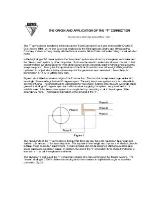
- 1. THE ORIGIN AND APPLICATION OF THE “T” CONNECTION By Alan Drew Chief Operations Officer, NLC The “T” connection is sometimes referred to as the “Scott Connection” as it was developed by Charles F. Scott around 1894. At the time Scott was employed by the Westinghouse Electric and Manufacturing Company and was working closely with the famous inventor Nikola Tesla on the alternating current induction motor. In the beginning of AC power systems the “two-phase” system was utilized by some power companies and the “three-phase” system by other companies. Scott saw the need to create a transformer connection that could transform two-phase power to three-phase power and to conversely transform three phase power to two-phase power. Among the first applications of the Scott Connection was at the original Niagara Falls hydroelectric project where the two-phase output of the generators was converted to three-phase for transmission at 11 kV to Buffalo, New York. Figure 1 shows the fundamental origin of the T connection. The round circle represents a generator with two single phase windings that are 90 degrees apart. The early two-phase systems were four-wire which seems confusing. The simplest way to understand the “two-phase” systems is to visualize two single phase generator windings 90 degrees apart each with two wires supplying the system. As you will notice the establishment of the three-phase system is accomplished by connecting a coil in the mid-point of the secondary winding. This midpoint connection is the concept of the “T”. Figure 1 The main benefit of the “T” connection is the fact that there are only two coils needed on the primary side and two coils needed on the secondary side. This equates to less weight and physical size which applicable to three-phase distribution transformers. A more compact unit can be designed which requires less pole space and makes installation easier. In addition, the cost of the “T” connection three-phase transformer is less than a three coil three phase transformer. The fundamental makeup of the “T” connection consists of a main winding and the “teaser” winding. The “teaser” winding is 0.866 % of the main winding which then creates an equilateral triangle as in a delta connection (fig. 2).
- 2. Figure 2 The other unique feature is that while the “T” connection does not have three full windings the T arrangement can simulate both Wye and Delta connections which makes it very versatile. By adding a neutral tap point on the teaser winding the center point of a wye connection is established as shown in fig. 3. Figure 3
- 3. The “T” connected transformer can efficiently supply the majority of common three-phase loads, however, experience has shown that for large three-phase motors that are frequently starting three-winding transformers are more efficient. The majority of today’s “T” connected transformers are three-phase pole mounted units. Again, this application is motivated by the more compact design that is achieved by using only two windings. There are also many “T” connected padmounted transformers in use supplying a wide a variety of both three-phase and single-phase loads. “T” connected transformers can be paralleled together by using standard paralleling procedures. “T” connected transformers should not be paralleled with conventional three winding transformers. Aed 8-10-06