1. Technological Studies Pneumatic Systems
1
Pneumatic Systems
1 Pneumatic systems............................................................................................3
(a) The advantages of pneumatic systems............................................................................. 3
(i) High effectiveness................................................................................................................................3
(ii) High durability and reliability..............................................................................................................3
(iii) Simple design.......................................................................................................................................3
(iv) High adaptability to harsh environment...............................................................................................4
(v) Safety ...................................................................................................................................................4
(vi) Easy selection of speed and pressure ...................................................................................................4
(vii) Environmental friendly ........................................................................................................................4
(viii)Economical ..........................................................................................................................................4
(b) Limitations of pneumatic systems ................................................................................... 4
(i) Relatively low accuracy.......................................................................................................................4
(ii) Low loading .........................................................................................................................................5
(iii) Processing required before use ............................................................................................................5
(iv) Uneven moving speed..........................................................................................................................5
(v) Noise....................................................................................................................................................5
(c) Main pneumatic components........................................................................................... 5
2 The production and transportation of compressed air.................................5
(a) Compressor ...................................................................................................................... 5
(b) Pressure regulating component........................................................................................ 6
3 The consumption of compressed air...............................................................7
(a) Execution component ...................................................................................................... 7
(i) Single acting cylinder ..........................................................................................................................7
(ii) Double acting cylinder.........................................................................................................................8
(b) Directional control valve ................................................................................................. 8
(i) 2/2 Directional control valve................................................................................................................9
(ii) 3/2 Directional control valve................................................................................................................9
(iii) 5/2 Directional control valve..............................................................................................................10
(c) Control valve.................................................................................................................. 10
(i) Non-return valve................................................................................................................................10
(ii) Flow control valve .............................................................................................................................11
(iii) Shuttle valve ......................................................................................................................................11
4 Principles of pneumatic control ....................................................................12
(a) Pneumatic circuit ........................................................................................................... 12
(b) Pneumatic circuit diagram............................................................................................. 12
(i) Basic rules..........................................................................................................................................12
(ii) Basic principles ............................................................................................................. 13
(iii) The setting of circuit diagrams..................................................................................... 14
5 Different kinds of basic circuits ....................................................................16
(a) Flow amplification......................................................................................................... 16
(b) Signal inversion............................................................................................................. 16
(c) Memory Function .......................................................................................................... 17
(d) Delay function ............................................................................................................... 17
(i) ON-signal delay .................................................................................................................................17
(ii) OFF-signal Delay...............................................................................................................................18
2. Technological Studies Pneumatic Systems
2
(e) Single acting cylinder control........................................................................................ 18
(i) Direct control and speed control ........................................................................................................18
(ii) OR Function.......................................................................................................................................19
(iii) AND Function....................................................................................................................................19
(iv) NOT Function ....................................................................................................................................20
(f) Double acting cylinder ................................................................................................... 20
(i) Direct control .....................................................................................................................................20
(ii) Single control.....................................................................................................................................21
6 The application of pneumatic systems..........................................................21
(a) Transport system............................................................................................................ 21
(b) Vehicle door operation system....................................................................................... 22
7 Safety measures when using pneumatic control systems............................23
Appendix: Pneumatic components ..................................................................24
Exercise...............................................................................................................28
3. Technological Studies Pneumatic Systems
3
Pneumatic Systems
1 Pneumatic systems
A pneumatic system is a system that uses compressed air to transmit and control energy.
Pneumatic systems are used in controlling train doors, automatic production lines, mechanical
clamps, etc (Fig. 1).
(a) Automobile production lines (b) Pneumatic system of an automatic machine
Fig. 1 Common pneumatic systems used in the industrial sector
(a) The advantages of pneumatic systems
Pneumatic control systems are widely used in our society, especially in the industrial sectors
for the driving of automatic machines. Pneumatic systems have a lot of advantages.
(i) High effectiveness
Many factories have equipped their production lines with compressed air supplies and movable
compressors. There is an unlimited supply of air in our atmosphere to produce compressed air.
Moreover, the use of compressed air is not restricted by distance, as it can easily be transported
through pipes. After use, compressed air can be released directly into the atmosphere without the
need of processing.
(ii) High durability and reliability
Pneumatic components are extremely durable and can not be damaged easily. Compared to
electromotive components, pneumatic components are more durable and reliable.
(iii) Simple design
The designs of pneumatic components are relatively simple. They are thus more suitable for
use in simple automatic control systems.
4. Technological Studies Pneumatic Systems
4
(iv) High adaptability to harsh environment
Compared to the elements of other systems, compressed air is less affected by high
temperature, dust, corrosion, etc.
(v) Safety
Pneumatic systems are safer than electromotive systems because they can work in inflammable
environment without causing fire or explosion. Apart from that, overloading in pneumatic system
will only lead to sliding or cessation of operation. Unlike electromotive components, pneumatic
components do not burn or get overheated when overloaded.
(vi) Easy selection of speed and pressure
The speeds of rectilinear and oscillating movement of pneumatic systems are easy to adjust
and subject to few limitations. The pressure and the volume of air can easily be adjusted by a
pressure regulator.
(vii) Environmental friendly
The operation of pneumatic systems do not produce pollutants. The air released is also
processed in special ways. Therefore, pneumatic systems can work in environments that demand
high level of cleanliness. One example is the production lines of integrated circuits.
(viii) Economical
As pneumatic components are not expensive, the costs of pneumatic systems are quite low.
Moreover, as pneumatic systems are very durable, the cost of repair is significantly lower than that
of other systems.
(b) Limitations of pneumatic systems
Although pneumatic systems possess a lot of advantages, they are also subject to many
limitations.
(i) Relatively low accuracy
As pneumatic systems are powered by the force provided by compressed air, their operation is
subject to the volume of the compressed air. As the volume of air may change when compressed or
heated, the supply of air to the system may not be accurate, causing a decrease in the overall
accuracy of the system.
5. Technological Studies Pneumatic Systems
5
(ii) Low loading
As the cylinders of pneumatic components are not very large, a pneumatic system cannot drive
loads that are too heavy.
(iii) Processing required before use
Compressed air must be processed before use to ensure the absence of water vapour or dust.
Otherwise, the moving parts of the pneumatic components may wear out quickly due to friction.
(iv) Uneven moving speed
As air can easily be compressed, the moving speeds of the pistons are relatively uneven.
(v) Noise
Noise will be produced when compressed air is released from the pneumatic components.
(c) Main pneumatic components
Pneumatic components can be divided into two categories:
1. Components that produce and transport compressed air.
2. Components that consume compressed air.
All main pneumatic components can be represented by simple pneumatic symbols. Each
symbol shows only the function of the component it represents, but not its structure. Pneumatic
symbols can be combined to form pneumatic diagrams. A pneumatic diagram describes the
relations between each pneumatic component, that is, the design of the system.
2 The production and transportation of compressed air
Examples of components that produce and transport compressed air include compressors and
pressure regulating components.
(a) Compressor
A compressor can compress air to the required pressures. It can convert the mechanical energy
from motors and engines into the potential energy in compressed air (Fig. 2). A single central
compressor can supply various pneumatic components with compressed air, which is transported
through pipes from the cylinder to the pneumatic components. Compressors can be divided into
two classes: reciprocatory and rotary.
6. Technological Studies Pneumatic Systems
6
(a) Compressor used in schools (b) Compressor used in (c) Pneumatic symbol of
laboratories a compressor
Fig. 2
(b) Pressure regulating component
Pressure regulating components are formed by various components, each of which has its own
pneumatic symbol:
(i) Filter – can remove impurities from compressed air before it is fed to the pneumatic
components.
(ii) Pressure regulator – to stabilise the pressure and regulate the operation of pneumatic
components
(iii) Lubricator – To provide lubrication for pneumatic components
(a) Pressure regulating component (b) Pneumatic symbols of the pneumatic
components within a pressure
regulating component
Fig. 3
7. Technological Studies Pneumatic Systems
7
3 The consumption of compressed air
Examples of components that consume compressed air include execution components
(cylinders), directional control valves and assistant valves.
(a) Execution component
Pneumatic execution components provide rectilinear or rotary movement. Examples of
pneumatic execution components include cylinder pistons, pneumatic motors, etc. Rectilinear
motion is produced by cylinder pistons, while pneumatic motors provide continuous rotations.
There are many kinds of cylinders, such as single acting cylinders and double acting cylinders.
(i) Single acting cylinder
A single acting cylinder has only one entrance that allows compressed air to flow through.
Therefore, it can only produce thrust in one direction (Fig. 4). The piston rod is propelled in the
opposite direction by an internal spring, or by the external force provided by mechanical movement
or weight of a load (Fig. 5).
Fig. 4 Cross section of a single acting cylinder
Fig. 5 (a) Single acting cylinder (b) Pneumatic symbol of a
single acting cylinder
The thrust from the piston rod is greatly lowered because it has to overcome the force from the
spring. Therefore, in order to provide the driving force for machines, the diameter of the cylinder
should be increased. In order to match the length of the spring, the length of the cylinder should
also be increased, thus limiting the length of the path. Single acting cylinders are used in stamping,
printing, moving materials, etc.
8. Technological Studies Pneumatic Systems
8
(ii) Double acting cylinder
In a double acting cylinder, air pressure is applied alternately to the relative surface of the
piston, producing a propelling force and a retracting force (Fig. 6). As the effective area of the
piston is small, the thrust produced during retraction is relatively weak. The impeccable tubes of
double acting cylinders are usually made of steel. The working surfaces are also polished and
coated with chromium to reduce friction.
Fig. 6 Cross section of a double acting cylinder
(b) Pneumatic symbol of a double
Fig. 7 (a) Double acting cylinder acting cylinder
(b) Directional control valve
Directional control valves ensure the flow of air between air ports by opening, closing and
switching their internal connections. Their classification is determined by the number of ports, the
number of switching positions, the normal position of the valve and its method of operation.
Common types of directional control valves include 2/2, 3/2, 5/2, etc. The first number represents
the number of ports; the second number represents the number of positions. A directional control
valve that has two ports and five positions can be represented by the drawing in Fig. 8, as well as its
own unique pneumatic symbol.
Fig. 8 Describing a 5/2 directional control valve
9. Technological Studies Pneumatic Systems
9
(i) 2/2 Directional control valve
The structure of a 2/2 directional control valve is very simple. It uses the thrust from the
spring to open and close the valve, stopping compressed air from flowing towards working tube ‘A’
from air inlet ‘P’. When a force is applied to the control axis, the valve will be pushed open,
connecting ‘P’ with ‘A’ (Fig. 9). The force applied to the control axis has to overcome both air
pressure and the repulsive force of the spring. The control valve can be driven manually or
mechanically, and restored to its original position by the spring.
Fig. 9 (a) 2/2 directional control valve (b) Cross section (c) Pneumatic symbol of a
2/2 directional control
valve
(ii) 3/2 Directional control valve
A 3/2 directional control valve can be used to control a single acting cylinder (Fig. 10). The
open valves in the middle will close until ‘P’ and ‘A’ are connected together. Then another valve
will open the sealed base between ‘A’ and ‘R’ (exhaust). The valves can be driven manually,
mechanically, electrically or pneumatically. 3/2 directional control valves can further be divided
into two classes: Normally open type (N.O.) and normally closed type (N.C.) (Fig. 11).
Fig. 10 (a) 3/2 directional control valve (b) Cross section
10. Technological Studies Pneumatic Systems
10
(a) Normally closed type (b) Normally open type
Fig. 11 Pneumatic symbols
(iii) 5/2 Directional control valve
When a pressure pulse is input into the pressure control port ‘P’, the spool will move to the left,
connecting inlet ‘P’ and work passage ‘B’. Work passage ‘A’ will then make a release of air through
‘R1’ and ‘R2’. The directional valves will remain in this operational position until signals of the
contrary are received. Therefore, this type of directional control valves is said to have the function
of ‘memory’.
(a) 5/2 directional control valve (b) Cross section (c) Pneumatic symbol
Fig. 12 5/2 directional control valve
(c) Control valve
A control valve is a valve that controls the flow of air. Examples include non-return valves,
flow control valves, shuttle valves, etc.
(i) Non-return valve
A non-return valve allows air to flow in one direction only. When air flows in the opposite
direction, the valve will close. Another name for non-return valve is poppet valve (Fig. 13).
Fig. 13 (a) Non-return valve (b) Cross section (c) Pneumatic symbol
11. Technological Studies Pneumatic Systems
11
(ii) Flow control valve
A flow control valve is formed by a non-return valve and a variable throttle (Fig. 14).
Fig. 14 (a) Flow control valve(b) Cross section (c) Pneumatic symbol
(iii) Shuttle valve
Shuttle valves are also known as double control or single control non-return valves. A shuttle
valve has two air inlets ‘P1’ and ‘P2’ and one air outlet ‘A’. When compressed air enters through
‘P1’, the sphere will seal and block the other inlet ‘P2’. Air can then flow from ‘P1’ to ‘A’. When
the contrary happens, the sphere will block inlet ‘P1’, allowing air to flow from ‘P2’ to ‘A’ only.
Fig. 15 (a) Shuttle valve (b) Cross section (c) Pneumatic symbol
12. Technological Studies Pneumatic Systems
12
4 Principles of pneumatic control
(a) Pneumatic circuit
Pneumatic control systems can be designed in the form of pneumatic circuits. A pneumatic
circuit is formed by various pneumatic components, such as cylinders, directional control valves,
flow control valves, etc. Pneumatic circuits have the following functions:
1. To control the injection and release of compressed air in the cylinders.
2. To use one valve to control another valve.
(b) Pneumatic circuit diagram
A pneumatic circuit diagram uses pneumatic symbols to describe its design. Some basic rules
must be followed when drawing pneumatic diagrams.
(i) Basic rules
1. A pneumatic circuit diagram represents the circuit in static form and assumes there is no
supply of pressure. The placement of the pneumatic components on the circuit also follows
this assumption.
2. The pneumatic symbol of a directional control valve is formed by one or more squares. The
inlet and exhaust are drawn underneath the square, while the outlet is drawn on the top.
Each function of the valve (the position of the valve) shall be represented by a square. If
there are two or more functions, the squares should be arranged horizontally (Fig. 16).
Fig. 16 3/2 directional control valve Fig 17 3/2 directional control valve
(normally closed type) (normally closed type)
3. Arrows "↓↖" are used to indicate the flow direction of air current. If the external port is
not connected to the internal parts, the symbol “┬” is used. The symbol “⊙” underneath
the square represents the air input, while the symbol “▽” represents the exhaust. Fig. 17
shows an example of a typical pneumatic valve.
4. The pneumatic symbols of operational components should be drawn on the outside of the
squares. They can be divided into two classes: mechanical and manual (Fig. 18 and 19).
13. Technological Studies Pneumatic Systems
13
(a) Vertical piston lever (b) Pulley lever (c) Unilateral pulley lever
Fig. 18 Mechanically operated pneumatic components
(a) Standard (b) Lever (c) Button (d) Pull & push
Fig. 19 Manually operated pneumatic components
5. Pneumatic operation signal pressure lines should be drawn on one side of the squares, while
triangles are used to represent the direction of air flow (Fig. 20).
Fig. 20 Pneumatic operation signal pressure line
(ii) Basic principles
Fig. 21 shows some of the basic principles of drawing pneumatic circuit diagrams, the
numbers in the diagram correspond to the following points:
Fig. 21 Basic principles of drawing pneumatic circuit diagrams
1. When the manual switch is not operated, the spring will restore the valve to its original
position.
2. From the position of the spring, one can deduce that the block is operating. The other block
will not operate until the switch is pushed.
3. Air pressure exists along this line because it is connected to the source of compressed air.
4. As this cylinder cavity and piston rod are under the influence of pressure, the piston rod is
in its restored position.
5. The rear cylinder cavity and this line are connected to the exhaust, where air is released.
14. Technological Studies Pneumatic Systems
14
(iii) The setting of circuit diagrams
When drawing a complete circuit diagram, one should place the pneumatic components on
different levels and positions, so the relations between the components can be expressed clearly.
This is called the setting of circuit diagrams. A circuit diagram is usually divided into three levels:
power level, logic level and signal input level (Fig. 22).
Fig. 22 Power level, logic level and signal input level
15. Technological Studies Pneumatic Systems
15
The basic rules of circuit diagram setting are as follows:
1. 2.
In a pneumatic circuit, the flow of energy is from the
bottom to the top. Therefore, the air supply unit
should be put at the bottom left corner.
The work cycle should be drawn from left to right.
The first operating cylinder should be placed at the
upper left corner.
3.
Power control valves should be drawn directly under
the cylinder controlled by them, forming a power unit.
4.
Control cylinders and operational valves (signal
components) driven by power control valves should
be placed at the lower levels of the diagram.
5. 6.
Assistance valves, such as those with logic functions
(for example, memory, ‘AND’, ‘OR’, ‘NOT’, delay,
etc), can be put between the pneumatic components
and the power control valves.
Use the line which represents the connecting pipe to
connect all the air supply unit and the pneumatic
components to complete the pneumatic circuit.
Check carefully the circuit and the logic of the
operation before use to avoid any accident.
16. Technological Studies Pneumatic Systems
16
5 Different kinds of basic circuits
A basic circuit is a pneumatic circuit designed to perform basic tasks, such as flow
amplification, signal inversion, memory, delay, single acting cylinder control, double acting
cylinder control, etc.
(a) Flow amplification
Cylinders with a large capacity require a larger flow of air, which can be hazardous to users. It
is unsafe to manually operate pneumatic directional control valves with large flow capacity. Instead
we should first operate manually a small control valve and use it to operate the pneumatic control
system with large flow capacity. This is called flow amplification, which can greatly ensure the
safety of the operators. During operation, valves with large flow capacity should be placed near the
cylinder, while valves with smaller flow capacity should be placed on control boards some distances
away. Fig. 23 shows a basic flow amplification circuit. Notice how different components are placed
on different levels.
Fig. 23 Flow amplification system
(b) Signal inversion
The pneumatic diagram in Fig. 24 shows how directional control valves can be switched.
When operating control valve , control valve will stop producing pressure output. When
control valve ceases operation and is restored to its original position, control valve will
resume its output. Therefore, at any given time, the pressure output of control valve is the exact
opposite of that of control valve .
Fig. 24 Signal inversion system
17. Technological Studies Pneumatic Systems
17
(c) Memory Function
Memory is a common basic function. It can keep a component at a certain state
permanently until there is a change of signals. Fig. 25 shows a memory function circuit. When
control valve is operated momentarily (that is, pressed for a short time), the output signal of the
5/2 directional control valve will be set to ON. The signal will stay that way until control valve
is operated momentarily and generates another signal to replace it, causing it to stay permanently
at OFF.
Fig. 25 Memory function circuit
(d) Delay function
A pneumatic delay circuit can delay the operating time of the next control valve. Its principle
of operation involves the use of an orifice to slow down the flow of air and control the time of
pneumatic operation. Delay functions can be divided into two classes: ON-signal delay and OFF-
signal delay.
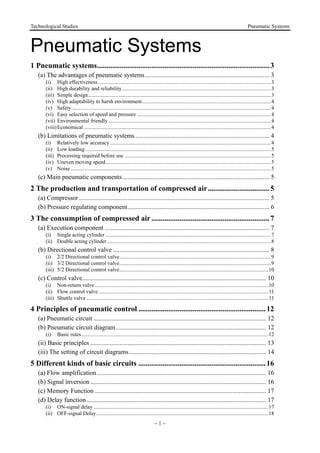
(i) ON-signal delay
Fig. 26 shows the circuit diagram of an ON-signal delay circuit, which delays the output of the
next control valve. When control valve is operated, the one way flow control valve will slow
down the flow of air, thus delaying the signal output of the outlet of control valve (A), resulting
in a persistent ON-signal. The time when control valve will be restored to its original position is
not affected.
Fig. 26 Circuit diagram of an ON-signal delay circuit
18. Technological Studies Pneumatic Systems
18
(ii) OFF-signal Delay
Fig. 27 shows the circuit diagram of an OFF-signal delay circuit, which delays the output of
the next control valve. This circuit is similar to an ON-signal delay circuit. The only difference is
that the one way flow control valve is connected in the opposite direction. Therefore, when control
valve is operated, the outlet of control valve (A) will continue to output signals. However,
when control valve is restored to its original position, the release of air is slowed down by the
one way flow control valve, resulting in a persistent OFF-signal.
Fig. 27 Circuit diagram of an OFF-signal delay circuit
(e) Single acting cylinder control
Single acting cylinders can be controlled manually. However, they can also be controlled by
two or more valves. This is called logic control. Examples of logic control include ‘OR’ function,
‘AND’ function, ‘NOT’ function, etc.
(i) Direct control and speed control
If a single acting cylinder is connected to a manual 3/2 directional control valve, when the
control valve is operated, it will cause the cylinder to work (Fig. 28). Therefore, the circuit allows
the cylinder to be controlled manually.
Fig. 28 Direct control of a single acting cylinder
The only way to change the extension speed of the piston of a single acting cylinder is to
restrict the flow of air at the inlet and use the spring to determine the speed of retraction. Therefore,
a one way flow control valve is placed in the circuit to control the speed.
19. Technological Studies Pneumatic Systems
19
(ii) OR Function
The single acting cylinder in Fig. 29 can be operated by two different circuits. Examples
include manual operation and relying on automatic circuit signals, that is, when either control valve
or control valve is operated, the cylinder will work. Therefore, the circuit in Fig. 29 possesses
the OR function. However, if the output of two 3/2 directional control valves are connected through
the port of a triode, the air current from control valve will be released through the exhaust of
control valve , and so the cylinder will not work. This problem can be solved by connecting a
shuttle valve to the port of the triode.
Fig. 29 Circuit diagram of an OR function circuit
(iii) AND Function
Another name for an AND function is interlock control. This means control is possible only
when two conditions are satisfied. A classic example is a pneumatic system that works only when
its safety door is closed and its manual control valve is operated. The flow passage will open only
when both control valves are operated. Fig. 30 shows the circuit diagram of an AND function
circuit. The cylinder will work only when both valve and are operated.
Fig. 30 Circuit diagram of an AND function circuit
20. Technological Studies Pneumatic Systems
20
(iv) NOT Function
Another name for a NOT function is inverse control. In order to hold or lock an operating
conveyor or a similar machine, the cylinder must be locked until a signal for cancelling the lock is
received. Therefore, the signal for cancelling the lock should be operated by a normally open type
control valve. However, to cancel the lock, the same signal must also cancel the locks on other
devices, like the indication signal in Fig. 31. Fig. 31 shows how the normally closed type control
valve can be used to cut off the normally open type control valve and achieve the goal of
changing the signal.
Fig. 31 Circuit diagram for a NOT function circuit
(f) Double acting cylinder
(i) Direct control
The only difference between a single acting cylinder and a double acting cylinder is that a
double acting cylinder uses a 5/2 directional control valve instead of a 3/2 directional control valve
(Fig. 32). Usually, when a double acting cylinder is not operated, outlet ‘B’ and inlet ‘P’ will be
connected. In this circuit, whenever the operation button is pushed manually, the double acting
cylinder will move back and forth once.
Fig. 32 Circuit diagram of a double acting cylinder direct control circuit
21. Technological Studies Pneumatic Systems
21
In order to control the speed in both directions, flow control valves are connected to the inlets
on both sides of the cylinder. The direction of the flow control valve is opposite to that of the
release of air by the flow control valve of the single acting cylinder. Compared to the throttle inlet,
the flow control valve is tougher and more stable. Connecting the circuit in this way allows the
input of sufficient air pressure and energy to drive the piston.
(ii) Single control
A cylinder always has to maintain its position in a lot of situations, even after the
operational signal has disappeared. This can be achieved by the use of a circuit that possesses
the memory function. As shown in Fig. 33, the extension path of a double acting cylinder is
activated by control valve , while retraction is governed by control valve . Control valve ,
on the other hand, maintains the position of the cylinder by maintaining its own position.
Control valve will be changed only when one of the manual control valves is pushed. If both
control valves and are operated at the same time, control valve will be subject to the
same pressure and will remain in its original position.
Fig. 33 Circuit that maintains the position of a double acting cylinder
6 The application of pneumatic systems
The application of pneumatic systems is very extensive. The following are some examples.
(a) Transport system
Fig. 34a shows a simplified industrial transport system. When the button switch is pushed, the
cylinder will push one of the goods from the shelf onto the transfer belt. When the button switch is
released, the cylinder will retract automatically. Fig. 34b shows the circuit diagram of the transport
system.
22. Technological Studies Pneumatic Systems
22
(a) Operation of a pneumatic transport system (b) Pneumatic circuit diagram
of a pneumatic transport system
Fig. 34
(b) Vehicle door operation system
Pneumatic systems can be used to operate the doors of public vehicles (Fig. 35a). Assuming
that the opening and closing of the doors are controlled by two button switches ON and OFF. When
the button switch ON is pressed, the doors will open. When the button switch OFF is pushed, the
doors will close. Fig. 35b shows a pneumatic system that can be used to operate the doors of
vehicles.
Fig. 35 (a) Operation of a pneumatic system that (b) Pneumatic circuit diagram
controls the movement of vehicle doors
23. Technological Studies Pneumatic Systems
23
7 Safety measures when using pneumatic control
systems
(a) Compressed air can cause serious damage to the human body if they enter the body through
ducts like the oral cavity or ears.
(b) Never spray compressed air onto anyone.
(c) Under high temperature, compressed air can pass through human skin.
(d) Compressed air released from the exhaust contains particles and oil droplets, which can cause
damage to eyes.
(e) Even though the pressure of compressed air in pipes and reservoirs is relatively low, when the
container loses its entirety, fierce explosions may still occur.
(f) Before switching on a compressed air supply unit, one should thoroughly inspect the whole
circuit to see if there are any loose parts, abnormal pressure or damaged pipes.
(g) A loose pipe may shake violently due to the high pressure built up inside it. Therefore, each
time before the system pressure is increased, thorough inspection of the entire circuit is
required to prevent accidents.
(h) As the force produced by pneumatic cylinders is relatively large, and the action is usually very
fast, you may suffer serious injuries if you get hit by a cylinder.
(i) Switches should be installed on the compressed air supply unit to allow easy and speedy
control of air flow.
(j) In case of a leakage, the compressed air supply unit should be turned off immediately.
(k) The compressed air supply unit must be turned off before changes can be made to the system.
(l) Stay clear of the moving parts of the system. Never try to move the driving parts in the
mechanical operation valve with your hand.
24. Technological Studies Pneumatic Systems
24
Appendix: Pneumatic components
There may exist differences in appearance and sizes of pneumatic components produced by
different manufacturers. However, the functions and operating methods among these components
are similar. The following are the pictures and cross section diagrams of the pneumatic components
made by another manufacturer for your reference.
1. Pneumatic components for the production and transportation of compressed air
(a) Compressor
Fig. 36 (a) Compressor (b) Pneumatic symbol
(b) Pressure regulating component
Fig. 37 (a) Pressure regulating component (b) Cross section of pressure regulating
component
(c) Pneumatic symbol
25. Technological Studies Pneumatic Systems
25
2. Pneumatic components for consumption of compressed air
(a) Single acting cylinder
Fig. 38 (a) Single acting cylinder (b) Cross section of a single acting cylinder
(c) Pneumatic symbol
(b) Double acting cylinder
Fig. 39 (a) Double acting cylinder (b) Cross section of a double acting cylinder
(c) Pneumatic symbol
26. Technological Studies Pneumatic Systems
26
(c) 3/2 Directional control valve
Fig. 40 (a) 3/2 Directional control valve (b) Cross section of a 3/2 directional
control valve
(c) Pneumatic symbols (a) Normally closed type (b) Normally open type
(d) 5/2 Directional control valve
Fig. 41 (a) 5/2 Directional control valve (b) Cross section (c) Pneumatic symbol
(e) Flow control valve
Fig. 42 (a) Flow control valve (b) Cross section (c) Pneumatic symbol
28. Technological Studies Pneumatic Systems
28
Exercise
1. List six advantages of using pneumatic systems.
2. State the limitations of using pneumatic systems.
3. What are the components that regulate the pressure?
4. State the difference(s) between a single acting cylinder and a double acting cylinder.
5. State the functions and classification of directional control valves.
6. What are the basic functions of a pneumatic control system?
7. Draw the following symbols of the pneumatic components:
Type Symbol Type Symbol
(a) Compressor (h) Manual control
valve
(b) Cylinder (i) Push button
control valve
(c) Filter (j) Vertical piston
lever control
valve
(d) Single acting cylinder (k) Pulley lever
control valve
(e) Double acting cylinder (l) Non-return valve
(f) 3/2 directional control
valve
(m) Flow control
valve
(g) 5/2 directional control
valve
8. Draw a signal inversion circuit.
9. Draw a pneumatic circuit with memory function.
10. Draw a pneumatic circuit of a double cylinder with its piston staying at the end of the cylinder.