
Recomendados
Más contenido relacionado
La actualidad más candente
La actualidad más candente (20)
Destacado
Similar a Theory of machines 1 mabie
Similar a Theory of machines 1 mabie (20)
Último
Último (20)
Theory of machines 1 mabie
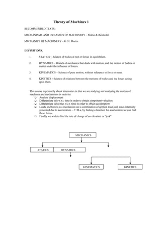
- 1. Theory of Machines 1 RECOMMENDED TEXTS: MECHANISMS AND DYNAMICS OF MACHINERY – Mabie & Reinholtz MECHANICS OF MACHINERY – G. H. Martin DEFINITIONS. 1. STATICS – Science of bodies at rest or forces in equilibrium. 2. DYNAMICS – Branch of mechanics that deals with motion, and the motion of bodies or matter under the influence of forces. 3. KINEMATICS – Science of pure motion, without reference to force or mass. 4. KINETICS - Science of relations between the motions of bodies and the forces acting upon them. This course is primarily about kinematics in that we are studying and analysing the motion of machines and mechanisms in order to: Analyse displacement Differentiate this w.r.t. time in order to obtain component velocities Differentiate velocities w.r.t. time in order to obtain accelerations Loads and forces in a mechanism are a combination of applied loads and loads internally generated due to acceleration – F=M.a, by finding a function for acceleration we can find these forces. Finally we wish to find the rate of change of acceleration or “jerk” MECHANICS STATICS DYNAMICS KINEMATICS KINETICS
- 2. HOW IS A MACHINE MADE? What are its constituents parts and how do they link together Machine parts are known as “elements” Two elements in relative motion and in contact are known as a “pair” The element joining pairs together is known as a “link”. A group of links and elements that are joined together is a “kinematic chain”. Fix one link of the kinematic chain and the chain becomes a “mechanism” Apply force with the mechanism and it becomes a ”machine” DEFINITIONS. MECHANISM – Is an assemblage of (rigid) bodies formed and connected in such a manner that they move upon each other with definite relative motion. (A chain/belt/cable is non-rigid yet can be used in a mechanism. Another example of this would be air or hydraulic fluid used in a pneumatic or hydraulic system – they are not rigid in the true sense yet are used to transmit motion). MACHINE - a mechanism, or collection of mechanisms which transmit force from the source of power to the resistance to be overcome. Another definition is that a machine is a combination of resistant bodies so arranged that by their means the mechanical forces of nature can be compelled to do work accompanied by certain determinate motions. NOTE A mechanism is therefore kinematically described, its motion is what determines it as a mechanism. A machine on the other hand is a mechanism which does work. Rigid structure, truss, etc – Statics Mechanism – Kinematics Machine – Kinetics EXAMPLES OF MECHANISMS: CRANK LEVER RECIPROCATING DRIVE – Connected to piston pump CRANK – Rotating element which may convert rotational motion into reciprocal or vice-versa Diagram 1
- 3. SLIDER CRANK - ENGINE MECHANISM Standard engine layout for two and four stroke internal combustion engines Diagram 2 BELL CRANK Used in motorcycle rear brakes – gives approximation to linear motion over short distances. Diagram 3
- 4. PIVOTING PISTON CRANK Used in early steam engines. The valves opened and closed as the cylinder oscillated to allow steam enter and exit the cylinder. Diagram 4 FOUR BAR LINKAGE Also known as a parallogram linkage. Used extensively to transmit motion from one crank to another using a connecting rod. Motion may be reciprocal or fully rotational on the part of either crank – This is dependent on the relationship between the crank lengths, connecting rod length and the distance between the two fixed centres. Diagram 5
- 5. Changeover points or change points are shown below. This is where direction of rotation may be reversed on one or other crank. On old railway locomotives the two sets of wheels on opposite sides of the train had the four-bar linkages displaced or out-of-phase by 90 degrees to ensure that no matter what position the train stopped in there would be no danger of wheel direction of rotation being incorrect. Diagram 6 If direction of rotation on one crank is opposite to that on the other then what is known as a butterfly arrangement will be obtained. Diagram 7 MORE MECHANISM DEFINITIONS LINK Machine part or component of mechanism assumed rigid (but not necessarily so for example a chain, belt, hydraulic fluid, cable, etc) DRIVER Input link or crank. Where the power comes from is typically a motor. Whether its an AC, DC, diesel, petrol, etc. in 99% of cases input power or motion to a machine or a mechanism is in the form of a rotating shaft. CYCLE When the parts of a mechanism or machine have passed through all the possible positions the can assume and have returned to their original positions they have completed a full cycle of motion. PERIOD Time required for a full cycle of motion – typically 360 degrees rotation of the input crank.
- 6. PHASE The simultaneous relative position of the links at any instant during the cycle of motion for the mechanism constitute a phase. Phase is the word used to describe where the mechanism “is in its cycle of motion” at any moment in time. We use the words “in-phase” to describe two systems whose positions are complimentary, compatible or equivalent in some way at some specific moment in time. PAIRING ELEMENTS (Kinematic Pairs) In order to transmit motion from the driver to the follower for example the links must be connected together in some manner. Connections between links are called Kinematic Pairs. Two bodies in contact constitutes a pair. Looking back at the mechanisms shown so far it is possible to see that most links are joined to two other links and thus may be said to be part of not one but two pairs. KINEMATIC CHAIN A number of links connected by means of pairs makes a Kinematic Chain. CONSTRAINED KINEMATIC CHAIN = MECHANISM A constrained Kinematic chain is a mechanism as the constraint implies that a fixed link is present as a frame of reference.e.g base or foundation. Without there being a fixed link whose position is defined there can be no frame of reference for the motion of the assembly of links. Without this ability to absolutely define the motion of each element there is no mechanism. CONSTRAINED CHAIN Relative motion of the links always the same. In the figure below for the same position “x” of link 5 there are two possible arrangements of links 3 and 4. Links 3 and 4 are unconstrained therefore this is not a mechanism instead its an Unconstrained Kinematic Chain i.e. Were link s 2 and 4 to be directly connected then it would be a constrained chain. Diagram. 8 LOCKED CHAIN If no motion at all were possible then a locked chain is obtained – also known as a structure or truss. Diagram. 9
- 7. CLOSED CHAIN Most mechanisms consist of closed chains wherein each link is connected to at least two others in the system. AN example of this would be the early radial aircraft engine type OPEN CHAIN An example of an open chain would be a pendulum – links with only one joint (but touches another link intermittently) JOINT TYPES More than two links may join at the same point and examples of these types of joint are given below: All these types of links may be used to form an open mechanism. Diagram 10 PAIRS A Pair is basically two (linked/ connected/joined/touching/links in contact) links. The nature of the connection between the two links defines the pair type – i.e. the relative motion which the links are permitted. HIGHER AND LOWER KINEMATIC PAIRS: LOWER PAIRING: ► Two surfaces are in contact i.e. piston and cylinder, pivot etc. – slider. HIGHER PAIRING ► Contact is at a point, or along a line e.g. ball bearing, roller bearing, gear teeth, cam surfaces *Wear is higher at higher pairs.
- 8. WRAPPING PAIR ► Chain & sprocket, belt & pulley, cable/drum. ANALYSIS For the purposes of kinematic analysis we usually assumes a perfect fit occurs at a joint, i.e, no dead band or clearance