Your FRAME for Your Promotion Event
•
0 recomendaciones•325 vistas

Presentation system for the point of sale. Mobile Action-Area ModuleSystem. More Infos: http://www.rappich.de/en/presentation-systems

Recomendados
Más contenido relacionado
Destacado
Similar a Your FRAME for Your Promotion Event
Similar a Your FRAME for Your Promotion Event (20)
Más de RAPPICH SYSTEMBAU GmbH & Co.KG
Más de RAPPICH SYSTEMBAU GmbH & Co.KG (9)
Último
Último (20)
Your FRAME for Your Promotion Event
- 2. RAPPICH SYSTEMBAU GmbH & Co. KG PLANNING of possible frame versions with backlit graphic areas RS FRAME Presentation System - Mobile Action Area Superstructure Page 1
- 3. RS FRAME RAPPICH SYSTEMBAU GmbH & Co. KG Ground plan with main dimensions – Erection instructions, parts 1 and 2 The main dimensions of the action area superstructure - exclusive of the action floor - are L/W/H 5.65 x 4.00 x 2.85m. The graphic areas can be designed individually according to customer requirements. Further information upon request. Erection stage, Part 2Erection stage, Part 1 Perspective Plan view Component spacing Componentspacing Note: 1. Erect light columns (component 1), spacing – see Erection stage 2 2. Attach components 2 and screw together components 1 and 2 Note: 3. Screw together components 3 and component 2 4. Install lattice girders (component 4) Presentation System - Mobile Action Area Superstructure Page 2
- 4. RS FRAME RAPPICH SYSTEMBAU GmbH & Co. KG Side view with main dimensions – Erection instructions, parts 3 and 4 Erection stage, Part 3 Perspective Note: 5. Install 16 upper horizontal lightboxes (component 5) and attach them to component 4 6. Install component 6 and connect electric power supply of the upper lightboxes using component 6 Erection stage, Part 4 Perspective Note: 7. Install component 7 (ceiling sails) Presentation System - Mobile Action Area Superstructure Page 3
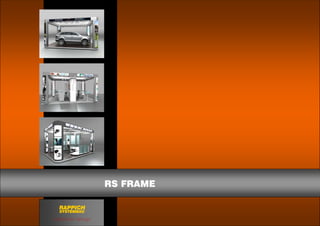
- 5. RAPPICH SYSTEMBAU GmbH & Co. KG RS FRAME IMPLEMENTAION of possible frame versions Presentation System - Mobile Action Area Superstructure Page 4
- 6. RAPPICH SYSTEMBAU GmbH & Co. KG RS FRAME IMPLEMENTAION of possible frame versions Presentation System - Mobile Action Area Superstructure Page 5
- 7. RAPPICH SYSTEMBAU GmbH & Co. KG D-09337 Callenberg OT Meinsdorf Langenberger Straße 28c Tel.: +49 (0) 3723/41 59 10 Fax.: +49 (0) 3723/41 59 12 E-Mail info@rappich.de exhibition design RAPPICH SYSTEMBAU RS FRAME