
Recomendados
Recomendados
Más contenido relacionado
Último
Último (20)
Destacado
Destacado (20)
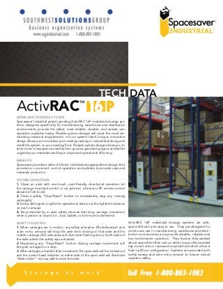
ActivRac 16P Mobilized Storage System - Technical Data
- 1. ActivRACTM TECH DATA MOBILIZED STORAGE SYSTEM Spacesaver Industrial patent pending ActivRAC 16P mobilized storage sys-tems, designed specifically for manufacturing, warehouse and distribution environments, provide the safest, most reliable, durable, and easiest user operation available today. Flexible system designs will meet the most de-manding industrial requirements. c-UL-us system listed. Unique, innovative design allows you to mobilize your existing racking or industrial shelving and install the system on your existing floor. Flexible system design allows you to store more in less space as well as free up value generating space and better organize your materials resulting in improved operational efficiency. BENEFITS Spacesaver provides a state-of-the-art, mobilized storage systems design that provides a convenient control operation and safeties to provide user and materials protection. SYSTEM OPERATION 1. Open an aisle with one-touch, user-friendly, directional operation (at the carriage mounted control or via optional infrared or RF remote control aboard a fork truck). 2. Press a safety “Stop/Reset” button to immediately stop any moving carriage(s). 3. Easily distinguish a system’s operational status via the lighted indicators on each carriage. 4. Be protected by in-aisle safety devices that stop carriage movement when a person or object (i.e., box, ladder, or fork truck) is detected. SAFETY FEATURES 1. When carriages are in motion, any safety activation (PhotoSweeps® and aisle entry sensors) will stop the aisle from closing on that aisle and the mobile carriage LED indicators will illuminate flashing red on both sides of the aisle where the safety was activated. 2. Depressing any “Stop/Reset” button during carriage movement will bring all carriages to a stop. 3. After carriages complete their movement the open aisle will be locked out and the control head indicator on either side of the open aisle will illuminate “Aisle in Use” - it’s now safe to enter the aisle. ActivRAC 16P mobilized storage systems are safe, space-efficient and easy to use. They are designed for continuous use in manufacturing, warehouse and distri-bution environments and provide durable, reliable and low maintenance operation. They feature fully-welded wheel assemblies that ride on either low profile beveled top mount rails or recessed mounted rails which allow a flush rail/floor configuration. Systems are provided with safety sweep and aisle entry sensors to ensure robust operator safety.
- 2. A. Powered Systems UÊ >ÀÀˆ>}iÊ `iÈ}˜Ê V>«>LˆˆÌÞÊ «iÀ“ˆÌÃÊ ÛˆÀÌÕ>ÞÊ Õ˜ˆ“ˆÌi`Ê V>ÀÀˆ>}iÊ layout configurations. UÊ -œv̇ÃÌ>ÀÌÊV>ÀÀˆ>}iÊ“œÛi“i˜ÌÊÀi`ÕViÃÊÃÞÃÌi“ÊÃÌ>À̇իÊ>“«iÀ>}iÊ draw and eliminates jostling of stored material during movement. UÊ *œÃˆÌˆÛiÊ`ˆÀiVÌÊÜ…iiÊ
- 3. Ê“œÌœÀÊ`ÀˆÛiÊ܈̅ÊÃœvÌÊÃÌ>ÀÌÉÃÌœ«]Ê`Þ˜>“ˆVÊ braking, current limiting and automatic time out. – Provides smooth, even carriage movement. – Protects material stored. – Provides longer system life. UÊ ˜vÀÀi`Ê`ˆÃ̘ViÊÃi˜ÃœÀÃÊvœÀÊ«ÀiVˆÃiÊVÀÀˆ}iÊ«œÃˆÌˆœ˜ˆ˜}° UÊ V‡1‡ÕÃÊÃÞÃÌi“ʈÃÌi`ÊÌœÊÃÃÕÀiÊiiVÌÀˆVÊÃviÌÞ° UÊ «Ìˆœ˜Ê`ÕÊVœ˜ÌÀœÃÊvœÀÊVViÃȘ}ÊÊÃÞÃÌi“Ê“œ`ÕiÊvÀœ“ÊLœÌ…Ê the front and rear. B. Top Mount Rail Design Option All rails are installed on top of concrete slab. UÊ ÎÉn»Ê ™°x““®Ê ÌÊ ÝÊ {‡£ÉÓ»Ê ££{““®Ê ܈`iÊ ÃÌiiÊ ÀˆÃÊ ÜˆÌ…Ê LVŽÊ zinc finish, with beveled edges. ADA compliant. UÊ ,ˆÊ ˜`Ê VÀÀˆ}iÊ `iÈ}˜Ê œÜÃÊ Vœ˜VÀiÌiÊ ÃLÊ ÌœÊ LiÊ Õ˜iÛiÊ ÌÊ the following maximum variation Ê qÊÎɣȻ{°n““®ÊÛÀˆÌˆœ˜ÊœÛiÀʘÞÊÓ½°È“®ÊÀˆÊÀÕ˜ Ê qÊ£É{»È°{““®Ê“݈“Õ“ÊÛÀˆÌˆœ˜ÊœÛiÀʘÞÊ£ä½Êΰä{“®ÊÀˆÊÀÕ˜ UÊ *ÀœÛˆ`iÃÊ“ˆ˜ˆ“ʈ˜ÌiÀÀի̈œ˜ÊœvÊ“ÌiÀˆÊ…˜`ˆ˜}ÊiµÕˆ«“i˜ÌÊ UÊ -œˆ`]ÊÌœ«Ê“œÕ˜Ìi`Êœ˜ÊyœœÀ]ÊÃÕ««œÀ̈˜}ÊÕ«Ê̜ʣÈ]äääÊLÃÊÇ]ÓxÇÊŽ}®Ê per wheel assembly. UÊ
- 5. iÈ}˜i`Ê̜ʜ«iÀÌiÊÕ˜`iÀÊ…iÛÞ]Êœ˜}‡ÌiÀ“]ÊVÞVˆVÊÃÌÀiÃÃÊœ`ð UÊ *ÀœÛˆ`iÃÊÌ…iÊÃœˆ`ÊLÈVÊvœÕ˜`̈œ˜ÊÀiµÕˆÀi`ÊvœÀÊ…iÛÞ‡`ÕÌÞÊ“œLˆ- lized storage systems assuring low maintenance and easy operation. C. Recessed Rail Design Option All rails are installed flush with concrete slab. UÊ ÎÉn»™°x““®ÊÌÊÝÊ·£ÉÓ»n™““®Ê܈`iÊÃÌiiÊÀˆÃÊ܈̅ÊLVŽÊ∘VÊ finish, designed to be installed flush into the concrete floor UÊ ,ˆÊ ˜`Ê VÀÀˆ}iÊ `iÈ}˜Ê œÜÃÊ Vœ˜VÀiÌiÊ ÃLÊ ÌœÊ LiÊ Õ˜iÛiÊ ÌÊ the following maximum variation Ê qÊÎɣȻ{°n““®ÊÛÀˆÌˆœ˜ÊœÛiÀʘÞÊÓ½°È“®ÊÀˆÊÀÕ˜ Ê qÊ£É{»È°{““®Ê“݈“Õ“ÊÛÀˆÌˆœ˜ÊœÛiÀʘÞÊ£ä½Êΰä{“®ÊÀˆÊÀÕ˜ UÊ *ÀœÛˆ`iÃÊ yÕÃ…Ê ˜œ˜‡ˆ˜ÌiÀÀÕ«Ìi`Ê ÌÀ˜ÃˆÌˆœ˜Ê vœÀÊ “ÌiÀˆÊ …˜`ˆ˜}Ê equipment UÊ -œˆ`]ÊyÕÃ…Ê“œÕ˜Ìi`ʈ˜ÊyœœÀ]ÊÃÕ««œÀ̈˜}ÊÕ«Ê̜ʣÈ]äääÊLÃÊÇ]ÓxÇÊŽ}®Ê per wheel assembly. UÊ
- 7. iÈ}˜i`Ê̜ʜ«iÀÌiÊÕ˜`iÀÊ…iÛÞ]Êœ˜}‡ÌiÀ“]ÊVÞVˆVÊÃÌÀiÃÃÊœ`ð UÊ *ÀœÛˆ`iÃÊÌ…iÊÃœˆ`ÊLÈVÊvœÕ˜`̈œ˜ÊÀiµÕˆÀi`ÊvœÀÊ…iÛÞ‡`ÕÌÞÊ“œLˆ- lized storage systems assuring low maintenance and easy operation. D. Wheels UÊ È»Ê£xÓ““®Ê
- 9. ÀˆÛiÊ7…iià UÊ *ÀiVˆÃˆœ˜Ê“V…ˆ˜i`ÊÃœˆ`ÊÃÌiiÊÜ…iið – Provide easy movement. – Prevent premature wear. – Roll easier than smaller wheels. E. Carriage Base/Rack Flue Spacer Articulation ( Back to Back Racking Configuration) UÊ ˜LiÃÊÃÞÃÌi“ÊÌœÊLiʈ˜ÃÌi`Êœ˜ÊÌÞ«ˆVÊi݈Ã̈˜}ÊVœ˜VÀiÌiÊyœœÀÃÊ without the need for leveled rails, footings, or second floor installation UÊ œÜÃÊÃÞÃÌi“ÊÌœÊÌÀVŽÊ˜`ÊÌÀ˜ÃviÀÊÌ…iÊÀVŽÊœ`ˆ˜}ÊiµÕÞÊÌœÊ all carriage wheels. F. Uniframe Wheel Assemblies Carriage Base UÊ ÕÞÊÜi`i`ÊÕ˜ˆvÀ“iÊÜ…iiÊÃÃi“Lˆið – Provides maximum strength for the load and cyclic stress requirements of a mobile system. – One-piece construction assures wheel alignment. UÊ ÃÃi“Li`ÊÃÌÀÕVÌÕÀÊÃÌiiÊVÀÀˆ}iÊLÃiÊ…ÃÊʓ݈“Õ“ÊV«V- ˆÌÞÊ œvÊ £È]äääÊ LÃÊ Ç]ÓxÇÊ Ž}®Ê «iÀÊ Ãˆ˜}iÊ œÀÊ ÎÓ]äääÊ LÃÊ £{]x£{Ê Ž}®Ê back-to-back rack section. G. Multiple Synchronized Motors UÊ Õ“LiÀÊœvÊ“œÌœÀÃÊÛÀˆiÃÊ܈̅ʜ`]ÊÌ…iÀiLÞ]Ê«ÀœÛˆ`ˆ˜}ÊÌ…iÊ“œÃÌÊ cost effective design. UÊ *ÀœÛˆ`iÃÊÓœœÌ…]ÊiÛi˜ÊVÀÀˆ}iÊ“œÛi“i˜Ì° UÊ ˆ˜Ìˆ˜ÃÊ «Àœ«iÀÊ VÀÀˆ}iÊ ˆ}˜“i˜ÌÊ Ì…ÀœÕ}…Ê VœÃi`Ê œœ«Ê motor feedback and control on all individual motors within carriage regardless of length or weight load distribution. Eliminates racking and binding without the use of tubular or solid steel drive shaft systems. H. Cross Bracing UÊ ii«ÃÊÜ…iiÊÃÃi“LˆiÃʈ˜ÊiÝVÌʈ}˜“i˜Ì° UÊ *ÀœÛˆ`iÃÊÀˆ}ˆ`ÊLÃiÊvœÀÊÀVŽˆ˜}ÊœÀÊÃ…iÛˆ˜}° I. Photo Sweep® UÊ ÝÌi˜`ÃÊÌ…iÊi˜ÌˆÀiÊi˜}Ì…ÊœvÊLœÌ…ÊÈ`iÃÊœvÊÌ…iÊVÀÀˆ}i]ÊÃÌœ««ˆ˜}Ê movement and slightly backing carriage away when an obstruction is detected. UÊ ˜iʈ˜ÛˆÃˆLiʈ}…ÌÊLi“Ê«œÃˆÌˆœ˜i`ÊÌÊLœÌÌœ“Êi`}iÊœvÊiÛiÀÞÊVÀ- riage provides added safety. UÊ -̘`À`Êœ˜ÊÊV̈Û, Ê£È*Ê“œLˆˆâi`ÊÃÌœÀ}iÊÃÞÃÌi“ð J. Aisle Entry Sensor UÊ ÕÌœ“̈VÞÊÃÌœ«ÃÊœÀÊ«ÀiÛi˜ÌÃÊVÀÀˆ}iÊ“œÛi“i˜ÌÊÜ…i˜ÊÊÕÃiÀÊ enters an aisle. UÊ -…œÕ`Ê Ê ÕÃiÀÊ i˜ÌiÀÊ Ê VœÃˆ˜}Ê ˆÃi]Ê Ì…iÊ ÃÞÃÌi“Ê ÜˆÊ ÃÌœ«Ê Ê carriage movement and that aisle will need to be reset to resume operation. UÊ ˜ÕÊÀiÃiÌÊÌÊÌ…iÊœ«i˜i`ʈÃiÊ«ÀœÛˆ`iÃÊ``ˆÌˆœ˜ÊÃviÌÞÊLÞÊ prompting users to visually check the open aisle before resetting the system. UÊ -œˆ`Ê ÃÌÌiÊ VˆÀVÕˆÌÀÞÊ ˜`Ê «…œÌœiiVÌÀˆVÊ ÌiV…˜œœ}ÞÊ i˜ÃÕÀiÃÊ œ˜}Ê term system reliability. UÊ -̘`À`Êœ˜ÊÊV̈Û, Ê£È*Ê“œLˆˆâi`ÊÃÌœÀ}iÊÃÞÃÌi“ð K. Beacon Horn UÊ Ã…ˆ˜}ÊLiVœ˜ÊÜÀ˜ÃÊœvÊVÀÀˆ}iÊ“œÛi“i˜Ì° UÊ œÀ˜Ê ÜÀ˜ÃÊ œvÊ VÀÀˆ}iÊ “œÛi“i˜ÌÊ ˆ˜Ê ÀiÃÊ Ü…iÀiÊ LiVœ˜Ê cannot be seen. L. Covered Wiring Raceway UÊ *ÀœÌiVÌÃÊ܈Àˆ˜}ÊvÀœ“ÊLÕÃiʘ`ÊVœ˜Ì“ˆ˜Ìˆœ˜° DESIGN AND CAPABILITY
- 10. M O P Q M. Overhead Buss Bar Power Distribution System UÊ VViÃÃʈÃiÊV˜ÊLiÊÃÊÀ}iÊÃʘii`i`° UÊ ii«ÃʈÃiÊvÀiiÊvÀœ“Ê܈Àˆ˜}ÊœLÃÌÀÕV̈œ˜Ã° N. Programmable Features. (Optional) UÊ -ÞÃÌi“Ê…ÃÊœ«Ìˆœ˜Ê«Àœ}À““LiÊvÕ˜V̈œ˜Ã°Ê(*Interface from building management or security system will be required by customer) – System Priority Aisle – System Close Park Ê qÊ -ÞÃÌi“Ê œÃi`É ˆ}…ÌÊ*ÀŽI – System Fire Park* œÌiÊ*ÀŽÃʘ`ÊÕÌœ‡“œÛiÃÊV˜ÊÃœÊLiÊÌÀˆ}}iÀi`ÊLÃi`Êœ˜Ê̈“iÊœvÊ`ÞÊ and day of week. O. Infrared Remote. (Optional) UÊ ˜LiÃÊ œ«iÀÌœÀÊ œ˜Ê Ê vœÀŽÊ ÌÀÕVŽÊ ÌœÊ œ«iÀÌiÊ Ê ÃÞÃÌi“Ê Vœ˜ÌÀœÊ head within close proximity of the control head without the need to get off the truck. UÊ œ˜ÌÀœÃÊœÛiÊivÌ]ÊœÛiÊ,ˆ}…Ì]Ê-Ìœ«É,iÃiÌÊÜ…i˜Ê`ˆÀiVÌi`ÊÌÊÌ…iÊ control head and at the needed activation location. P. Radio Frequency Remote. (Optional) UÊ ˜LiÃÊœ«iÀÌœÀÊœ˜ÊÊvœÀŽÊÌÀÕVŽÊ̜ʜ«i˜Ê˜ÊˆÃiÊÀi“œÌiÞÊvÀœ“Ê Õ«Ê̜ʣäää½Ê܈̅ʘœÊLÕˆ`ˆ˜}ÊœÀÊÀ}iÊiµÕˆ«“i˜ÌÊœLÃÌÀÕV̈œ˜Ã]ÊœÀÊ Õ« Ìœ Îxä½ ÜˆÌ… œLÃÌÀÕV̈œ˜Ã° UÊ -ÞÃÌi“Ê“ÕÃÌÊÜʅÛiʈÃiÊi˜ÌÀÞÊÃi˜ÃœÀÃʘ`ÊÕÃi`ʈ˜ÊVœ˜Õ˜V̈œ˜Ê with the infrared remote so that the system must be in a clear or ready green state to activate the aisle with the RF remote remotely. If the system is in use, the RF Remote will not remotely open any re-quested aisle in the system. UÊ ÊȘ}iÊ,ÊÀi“œÌiʈÃÊV«LiÊœvÊVœ˜ÌÀœˆ˜}ÊÕ«ÊÌœÊÈÝÊÈ®ÊVÀÀˆ}iÃÊ ˆ˜Ê Ê Ãˆ˜}iÊ “œ`ÕiÊ ˜`Ê Õ«Ê ÌœÊ wvÌii˜Ê £x®Ê “œ`ÕiÃÊ vÀœ“Ê Ê Ãˆ˜}iÊ remote. Q. Power Override Unit. (Optional) UÊ ˜`…i`ÊÀiV…À}iLiÊLÌÌiÀÞÊÕ˜ˆÌÊi˜LiÃÊÊȘ}iÊVÀÀˆ}iÊÌœÊ be moved at a reduced speed if a power failure was to occur and the system needed to be accessed. R. Touch Pad Control (Optional) UÊ ˜ÊLiÊṎˆâi`ÊÌœÊVViÃÃÊÊÃÞÃÌi“Ê“œ`ÕiÊœÀÊëiVˆwVʈÃià UÊ iÌÕÀiÃÊ«ˆ˜ÊVViÃÃÊ܈̅ÊÕ`ˆÌÊÌÀˆÊV«LˆˆÌÞ UÊ ˜ÊÌÀVŽÊÜ…œÊ˜`ÊÜ…i˜ÊÃÞÃÌi“ÊœÀʈÃiʈÃÊVViÃÃi` UÊ ˜Êˆ“ˆÌÊVViÃÃÊÌœÊëiVˆwVʈÃiÃÊLÞÊÕÃiÀ S. Computer Interface (Optional) UÊ œ“«ÕÌiÀʈ˜ÌiÀvViÊœÜÃʈÃiÊÃiiV̈œ˜ÊÛˆÊ* ° ˜ÌiÀvViÊÌœÊ7-ÊœÀÊ ,*ÊÃÞÃÌi“Ê«ÀœÛˆ`i`ÊLÞÊVÕÃÌœ“iÀ® F B C G H D I J A K E
- 11. Rail- Top Mount: ,ˆÊÃ…ÊLi]Ê£ä£nÊÃÌiiÊLÀÊ{Ê£Éӻʣ£{““®Ê܈`iÊÝÊÎÉn»Ê™°x““®Ê high with black zinc finish. Rail edges shall be beveled down to a “݈“Õ“ÊœvÊÎɣȻÊ{°n““®Ê̜ʜÜÊvœÀÊÌ…iÊÀˆÊÌœÊLiÊÌÀ˜ÃÛiÀÃi`Ê by material handling equipment. Rail shall disperse the wheel point loads to structural slab. Rail shall have two permanently “œÕ˜Ìi`Ê yœœÀÊ ˜V…œÀÃÊ “݈“Õ“Ê £x»Ê În£““®Ê œ˜Ê Vi˜ÌiÀ°Ê ,ˆÃÊ shall be installed on top of concrete slab. Rail and carriage design allows concrete slab to be unlevel at the following maximum varia- ̈œ˜ÊœvÊÎɣȻÊ{°n““®ÊÛÀˆÌˆœ˜ÊœÛiÀʘÞÊÓ½Êä°È“®ÊÀˆÊÀ՘ʘ`Ê£É{»Ê È°{““®Ê“݈“Õ“ÊÛÀˆÌˆœ˜ÊœÛiÀʘÞÊ£ä½Êΰä{“®ÊÀˆÊÀÕ˜° Rail- Recessed Mount: ,ˆÊÃ…ÊLi]Ê£ä£nÊÃÌiiÊLÀÊÎÊ£ÉÓ»Ên™““®Ê܈`iÊÝÊÎÉn»Ê™°x““®Ê high with black zinc finish. Rail shall disperse the wheel point loads to structural slab. Rail shall have two permanently mounted floor ˜V…œÀÃʓ݈“Õ“Ê£x»ÊÎn£““®Êœ˜ÊVi˜ÌiÀ°Ê,ˆÊÃ…ÊLiʈ˜ÃÌi`Ê recessed into concrete slab and flush to top of concrete slab. Rail and carriage design allows concrete slab to be unlevel at the fol- œÜˆ˜}ʓ݈“Õ“ÊÛÀˆÌˆœ˜ÊœvÊÎɣȻÊ{°n““®ÊÛÀˆÌˆœ˜ÊœÛiÀʘÞÊÓ½Ê ä°È“®ÊÀˆÊÀ՘ʘ`Ê£É{»ÊÈ°{““®Ê“݈“Õ“ÊÛÀˆÌˆœ˜ÊœÛiÀʘÞÊ£ä½Ê ΰä{“®ÊÀˆÊÀÕ˜° Mobile Carriage Bases: Assembled structural steel carriage base will have a minumum capac- ˆÌÞÊœvÊ£È]äääÊLðÊÇ]ÓxÇÊŽ}®Ê«iÀÊȘ}iʘ`ÊÎÓ]äääÊLðʣ{]x£{ÊŽ}®Ê«iÀÊ back-to-back rack section. On back-to-back configurations, individual wheel assemblies must be connected with an articulated carriage base/rack flue spacers in order to have the system track and transfer the rack loading equally to all carriage wheels. Each wheel assembly Ã…ÊLiÊiµÕˆ««i`Ê܈̅ÊÌÜœÊÜ…iiÃ]Ê“ˆ˜ˆ“Õ“ÊȻʣxÓ““®Ê`ˆ“iÌiÀÊ steel wheels. Wheels are equipped with two permanently lubri- VÌi`ʘ`ÊÃ…ˆi`i`ÊÀ`ˆÊLÊLiÀˆ˜}ðÊ7…iiÊV«VˆÌÞÊn]äääÊLÃÊ Î]ÈÓnŽ}®ÊiV…°Ê7…iiÃÊ…ÛiÊÃœˆ`ÊÃÌiiÊÝiÃÊœvÊ£‡ÎÉn»Êˆ˜ÊÎx““®Ê diameter. Wheels shall be dual flange, all wheel guided. All car-riage sections between wheel assemblies have integral cross brac-ing to maintain accepted tolerances for function of systems. Side profiles shall provide and maintain wheel assembly alignment and squareness. These profiles shall be pre-drilled at the factory but are bolted, and assembled on the job site as integral carriage mem-bers. Wiring shall be routed through an enclosed housing chan-nel SPECIFICATIONS AND SAFETY to protect the electronic wiring harness. Structural steel side «ÀœwiÃÊÃ…ÊLiÊ“ˆ˜ˆ“Õ“ÊÈ°£Èx»Ê£xÇ““®Ê…ˆ}…]ÊnÊ}Õ}iÊ{°Ó““®°Ê Finish shall be powder coat paint. Structural bases shall be placed LVŽÊÌœÊLVŽÊ܈̅ʓˆ˜ˆ“Õ“ÊȻʣxÓ““®ÊViÀÊyÕiÊLiÌÜii˜ÊLVŽ‡ to-back carriages. Power Controls: -ÞÃÌi“Ê «œÜiÀÊ ÀiµÕˆÀi“i˜ÌÃÊ ‡Ê £ÓäÊ 6 Ê Ãˆ˜}iÊ «…ÃiÊ ˆ˜«ÕÌ°Ê *œÜ- iÀi`ÊVÀÀˆ}iÃÊÃ…ÊLiÊiµÕˆ««i`Ê܈̅ʥÊ*ÆÊ™ä‡ÛœÌÊ
- 12. Ê}iÀÊ“œ- ÌœÀðÊÊṎ«iÊVÀÀˆ}iÃÊÃ…ÊLiÊ“œÛi`Ê܈̅ÊÊȘ}iÊV̈Û̈œ˜ÊœvÊ a carriage control and/or via an infrared or RF remote. Each car- Àˆ}iÊÃ…ÊLiÊiµÕˆ««i`Ê܈̅ʜ˜iÊœÀÊ“œÀiÊ¥Ê*]Ê™ä‡ÛœÌÊ
- 13. Ê}iÀÊ motors, depending on load rating. Each independent drive shall be synchronous and current limiting to maintain proper alignment through closed loop motor feedback and control on all individual motors within the carriage regardless of length or weight load ˜`Ê iˆ“ˆ˜ÌiÊ ÀVŽˆ˜}Ê ˜`Ê Lˆ˜`ˆ˜}°Ê œÌœÀÊ ˜`Ê “œÌœÀÊ Vœ˜ÌÀœiÀÃÊ shall provide for soft-start/soft-stop movement, current limiting, and automatic time-out. Carriage movement to be selectable be-tween sequential to minimize power demands on start-up, or block “œÛi“i˜ÌÊvœÀÊvÃÌiÀÊVViÃÃʜ̜ÀÃʘ`Ê«œÜiÀÊÌÀˆ˜ÊÃ…Ê«ÀœÛˆ`iÊ vœÀʓ݈“Õ“ÊVÀÀˆ}iÊÌÀÛiÊëii`ÊœvÊλÊÇÈ““®Ê«iÀÊÃiVœ˜`°ÊÊÊ power transfer to wheels to be done by chain drive. Power to mobile units provided by an overhead buss bar system. Communica-tion between carriages is provided by overhead cable festoon. Power supply to be provided by others. Safety Features: /…iÊ vœœÜˆ˜}Ê ÃviÌÞÊ viÌÕÀiÃÊ ÀiÊ ÌœÊ LiÊ «ÀœÛˆ`i`Ê *…œÌœiiVÌÀˆVÊ safety sweep scanning the full length of both sides of each car-riage. The sweep will prevent or immediately stop movement if an obstruction is encountered or the beam is broken. Photoelectric aisle entry sensor shall be positioned at each entry location. The aisle entry beam will prevent or immediately stop movement if an obstruction is encountered or the beam is broken. Status of the safeties to be displayed on the control unit. Stop pushbutton shall be provided at each aisle control. A warning horn shall be pro-vided whereupon activation of an aisle movement pushbutton it ܈ÊÜ՘`ÊvœÀÊÌ…iÊwÀÃÌÊÎÊÃiVœ˜`ÃÊœvÊVÀÀˆ}iÊ“œÛi“i˜Ì°ÊÊyÃ…ˆ˜}Ê yellow warning light is provided on the carriage ends that will flash during system movement. Specifications are subject to change Patent Pending Spacesaver Corporation 1450 Janesville Avenue Fort Atkinson, WI 53538-2798 1-866-767-1888 www.spacesaverindustrial.com KI 1330 Bellevue Street P.O. Box 8100 Green Bay, WI 54302-8100 1-800-424-2432 www.ki.com Spacesaver Corporation is a division of KI. KI and Spacesaver are registered trademarks of Krueger International, Inc. © 2010 KI and Spacesaver Corporation. All Rights Reserved. Litho in USA. SC-1018 SSC/MAR 09/10