

Recomendados
Más contenido relacionado
La actualidad más candente
La actualidad más candente (20)
Destacado
Destacado (20)
Similar a Physics details
Similar a Physics details (20)
Último
Último (20)
Physics details
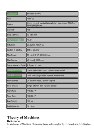
- 1. Make Model Honda CB 500E Year 1998-00 Engine Liquid cooled, parallel twin cylinder, four stroke, DOHC, 4 valve per cylinder, Capacity 499 Bore x Stroke 73 x 59 mm Compression Ratio 10.5:1 Induction 2X 32mm Keihin CV Ignition / Starting CDI / electric Max Power 58 hp 42.3 kW @ 9500 rpm Max Torque 47 Nm @ 8000 rpm Transmission / Drive 6 Speed / chain Front Suspension 37mm Telescopic forks, 115mm wheel travel, Rear Suspension Twin shock adjustable, 117mm wheel travel. Front Brakes 2x 296mm discs 2 piston calipers Rear Brakes Single 240mm disc 1-piston caliper Front Tyre 110/80-17 Rear Tyre 130/80-17 Dry-Weight 173 kg Fuel Capacity 18 Litres Theory of Machines References: 1- Mechanics of Machines: Elementary theory and examples. By: J. Hannah and R.C. Stephens .
- 2. 2- Mechanics of Machines: Advanced theory and examples. By: J. Hannah and R.C. Stephens . 3- Theory of Machine. By: R.S. Khurmi and J. K. Gupta. 4- Kinematics and Dynamics of Machines. By: G.H. Martin. Topics to be considered: 1. Kinematics and Kinetics of Mechanisms. 2. Balancing of Machines. a. For Rotating masses. b. For Reciprocating masses. 3. Cams and Followers. 4. Flywheel. 5. Gears and Gears trains. 6. Friction Clutches. 7. Belt drives and Band Brakes. 8. Power Screw. 9. Universal Joint. 10. Gyroscope. 11. Speed Governors. 12. Steering mechanism.
- 3. Chapter One Kinematics and Kinetics of Mechanisms Introduction: Theory of Machines: may be defined as that branch of engineering science, which deals with the study of relative motion between the various parts of machine, and forces which act on them. The knowledge of this subject is very essential for an engineer in designing the various parts of a machine. Sub- divisions of theory of Machines: They Theory of Machines may be sub- divided into the following four branches: 1- Kinematics: is that branch of theory of machines which is responsible to study the motion of bodies without reference to the forces which are cause this motion, i.e it’s relate the motion variables (displacement, velocity, acceleration) with the time. 2- Kinetics: is that branch of theory of machines which is responsible to relate the action of forces on bodies to their resulting motion. 3- Dynamics: is that branch of theory of machines which deals with the forces and their effects, while acting upon the machine parts in motion. 4- Statics: is that branch of theory of machines which deals with the forces and their effects, while the machine parts are rest.
- 4. There are some definitions which are concerned with this subject, must be known: Mechanism: is a combination of rigid bodies which are formed and connected together by some means, so that they are moved to perform some functions, such as the crank- connecting rod mechanism of the I.C. engines, steering mechanisms of automobiles……. etc. The analysis of mechanisms is a part of machine design which is concerned with the kinematics and kinetics of mechanisms (or the dynamics of mechanisms). Rigid Body: is that body whose changes in shape are negligible compared with its overall dimensions or with the changes in position of the body as a whole, such as rigid link, rigid disc…..etc. Links: are rigid bodies each having hinged holes or slot to be connected together by some means to constitute a mechanism which able to transmit motion or forces to some another locations. Absolute motion: the motion of body in relative to another body which is at rest or to a fixed point located on this body. Relative motion: the motion of body in relative to another moved body. Scalar quantities: are those quantities which have magnitude only e.g. mass, time, volume, density etc. Vector quantities: are those quantities which have magnitude as well as direction e.g. velocity, acceleration, force etc.
- 5. Disc in motion (rigid body) ω Slot, used for the purpose of connection with another link by slider. Rigid link Hinged hole Hinged hole used for the purpose the connection with another link by hinge pin Crank-Connecting rod mechanisms Fixed point hinge Piston moved on horizontal path Connecting rod crank
- 6. Part one: Kinematics of Mechanisms: 1- The connection of mechanism parts: The mechanism is a combination of rigid bodies which are connected together using different methods: 1-1: Hinged part: The hinge connection may be used to connect the links together or connect a link to a fixed point, piston, disc ….. etc, the connection is achieved using pin, which is pass through the hinge holes. Symbled by 1-2: Sliding Parts: The sliding connection may be used to connect two links rotate about fixed points by means of slot, pin and hinge. Symbled by Slot, pin and hinge Hinge and pin Hinge and pin
- 7. 1-3: Rolling without slipping parts: ω3 ω1 ω2 Symbled by 2- Translated bodies: There are some bodies in the mechanism which are constrained to move in translation manner, such as the piston of crank- connecting rod mechanism, the body is used to be in translation motion, if any line remain in some configuration during motion; then all the points have the same absolute velocity and acceleration. Velocity diagram: ∵ the motion is absolute, then select any fixed point such as o be as a reference point (i.e point of zero velocity). Draw the path of translation. If v is known, select a scale factor to draw the velocity diagram (denoted by SFv) B SFv= ⁄ The draw a line ob=(vB)(SFv) in direction of vB parallel to the path of translation.
- 8. Path of translation of B b V y vb o B , el di a D d oc g. b o it A Then all points on the piston have the same velocity, such as point D, i.e on the velocity diagram, the point d coincide on the point b. Acceleration diagram: ∵ the motion is absolute, then select any fixed point such as o be as a reference point (i.e point of zero acceleration). Draw the path of translation. If a is known, select a scale factor to draw the acceleration diagram (denoted by SFa) B SFa= ⁄ In which ob=(aB)(SFa). Then all points on the piston have the same acceleration value. Note: the base (ref.) point o of vo =0, ao=0.
- 9. Path of translation of B o b, d Acceleration dig. Dynamic review: Translation motion can by treatment by the dynamics of particles i.e body B can be treatment as a particle moved on straight or curved path. Then: , . Where: s: displacement ,v: velocity , a: acceleration ∫ , if a uniform . ∫ , if a uniform . . 3-Bodies rotate about fixed point: Consider the link shown which is rotate about the fixed point o, the motion of this link can be analyzed using the principle of absolute motion as follow: o D A v A a A If θ: a n g ul ar di s pl a c e m e nt a b o ut fi x e d ro ta ti o n ce nt re . ω : an g ul ar ve lo ci ty ab o ut fi xe d ro ta ti o n c e n tr e . α : a n g u l a r a c c e l e r a ti o n a b o u t fix ed rot atio n cen tre.
- 10. T h e n: ,, ⇒ ∫ b ut if α is u n if o r m a n d∫ but if α is uni for m . Velocity diagram: In order to analyze the velocity of any point we follow with one of following methods: 1- If ω is given: Draw the link by SFp (scale factor for position), SFp= v=. A Select SFv = then select a reference point of zero velocity, such as o. Draw from o, a line of length in direction of ω. To find the velocity of any point located on the link, such as D, specify point d on oa such that od=( ) Then:- .
- 11. 2- If vA is given: Select SFv, specify reference point of zero velocity. Draw oa of length (v )(SFv) in the same direction given. A To find value and direction of ω: velocity diagram a ram a d m o o d A :A a P o ls aAn=(oA) ω2 normal si o component of ti w acceleration of o e A relative to rotation n h d centre. ia a aAt=(oA) α normal g v component of r e acceleration of a t A relative to rotation m O D V a l u e o f . A c c e l e r a ti o n d i a g r w o m et h o d: 1 If α is gi v e n :- centre. Select a reference point of zero acceleration (point o) Select SFa . depend on which is greater aAn or aAt. Start from o to draw // OA directed into the rotation centre, by value of o aAn. SFa. From pointdraw OA in direction of α by value =aAt.SFa. Finally connect oa to represent the absolute value of acceleration of point A. . ac ce le ra ti o n di ag To find the acceleration of any point located on the link, such as point D. specify d on oa such that ()
- 12. 2 I f a A i s g i v e n a s a v al u e a n d di re ct io n. (a b s ol ut e acceleration of point A). Find . Select , select refrence point of zero acceleration. (point O). Start from O, draw two lines. First line directed in to point O. Second line in direction of aA (given). Then connect to represent the drawn tangential component of acceleration of A. acceleration diagram o d a aAt aAn . 4-Bodies under general plane motion:If a body under general plane motion, then it’s motion can be analyzed using the principle of relative motion. The motion of any point can be discretized into translation and rotation, if consider the link shown under general plane motion, the ends , B of absolute velocities vA, vB, and absolute accelerations aA, aB then:-
- 13. Where:is the relative velocity of B w.r.t A. A B Link AB aA aB VB is the rel ative velocity of A w.r.t B. VA is the relative acceleration of B w.r.t A. is the relative acceleration of A w.r.t B. i.e the state of velocity can be replaced by one of the following:} vector notation. ∵ VAB and VBA A B B A V A B A V B A B ∵ ω To sp ec ify di re cti on of ω: A B VB A VA B VA B VB A a b VA VB Fix ed poi nt
- 14. : mean that B is a fixed rotation a center, and A moved a round A. VAB VBA : mean that A is a fixed rotation a center, and A moved a round B. A B VAB VBA And the state of acceleration can be represented by one of the following:} vector notation. contain two comps.{ into in direction of α contain two comps.* into in direction of α A B aA A αBA αAB aB B
- 15. Velocity diagram: Consider the shown link under general plane motion, to specify the velocity of any point, it’s required one of following:1- * Absolute velocity of any point (value and direction). *Absolute velocity of other point (value or direction). 2- *Absolute velocity of any point (value and direction). *Angular velocity of the link which is the same for all points. Vc a y ci cti D n d t on ac d ia y. of ω d g ( VB ω ω ir r p . VB e a o C ct m i α i n aB B o ( t A n S O Ste ), F ). ps: t v h ). e o Dr n b aw s S k the el p n lin e e o k ct ci w po t f n siti h y i on e t n by s h m sca c e m le al p . (S e o Fp f i ). a n D ct t r I o o a f r f w VB o z o is f e b kn v r i ow el o n n o v d (va ci el ir lue t o e
- 16. To co nti nu e we req uir e oth er dir ect ion of abs olu te vel oci ty of oth er poi nt or ω. If the dir ect ion of abs olu te v el o ci t y o f p o i n t c is k n o w n t h e n : S ta r fr o m o t o d r a w li n e // d ir e ct i o n o f V c. S ta r fr o m b t o d r a w li n e li n k t o b e bc o r V cb , w h ic h is i n t e r s e c t e d w it h t h e li n e // d ir e c tio n of Vc at c. If ω is kn o w n: , th en . Dr aw bc fro m b lin k Dr a w lin e be tw ee n o a n d c p r o d u c e o c. T o fi n d V A, V D: S p e ci f y b a s u c h th at . M e a s u re o d V D = a d / S F v. T o fi n d ω v al u e a n d di re ct io n, if u n k n o w n m e a s u re b c . V C A B C . Acceleration diagram: To dr w the cceler tion di gr m it’s required one of following:1- ω or VBC. Absolute acceleration of any point (value and direction). Absolute acceleration of other point (value or direction). 2- ω or VBC.
- 17. Absolute acceleration of any point (value and direction). Angular acceleration of the link.
- 18. Steps: Find If a is known (value and direction), VB is known (direction). c Select SFa . Start from point of zero acceleration such as o. Draw oc in direction of a. c // link directed into point c (on the link). From o draw a line in directi n of aB o intersected at b. If α is known v lue nd direction . Start from to draw link. Connect ob Find aA , aD. Specify bc such that . Measure oa . Specify cd such that . Measure . To find α (value and direction) in unknown: Measure α d o b c a Acceleration diagram aBCt B BCt), they are
- 19. Note:- α is the same for all points of the link.
- 20. Example(1):- For the crank- connecting rod mechanism shown: OA= 10cm , AB= 30 cm, AC= 10 cm, it’s single degree of freedom, coordinate is . If =30 rad/sec, =100 rad/s2. Find , , VB , aB , aC , VC at = . α ω B C A O ⁄ . ⁄ ⁄ ⁄⁄ a o b c Mechanism drawn by scale 0.2 cm/cm ⇒() ⇒⁄ ⇒⁄ :⇒⁄ : ⁄ : Velocity drawn by scale 1 cm/m/s ⁄
- 22. Example(2):- In the mechanism shown in Fig. below, the link AB rotates with a uniform angular velocity of 30 rad/ s. Determine the velocity and acceleration of G for the configuration shown. The length of the various links are, AB=100 mm; BC=300 mm; BD=150 mm; DE=250 mm; EF=200 mm; DG=167 mm; angle CAB=30. To draw velocity diagram:⁄ ⁄ ⁄⁄ ⁄ Mechanism drawn by scale 0.2 ⁄ ⁄ ⁄ ⁄ ⁄ ⁄ ⁄ Velocity drawn by scale 13.33 ⁄⁄ ⁄
- 23. To draw the acceleration diagram:⁄ ⁄ ⁄ ⁄ ⁄ ⁄⁄ Acceleration drawn by scale 0.778 ⁄⁄ ⁄ ⁄ ⁄ ⁄ ⁄ ⁄ ⁄ ⁄ ⁄⁄ ⁄
- 24. Example(3):-Figure below shows the mechanism of a moulding press in which OA=80 mm, AB=320 mm, BC=120 mm, BD=320 mm. The vertical distance of OC is 240 mm and horizontal distance of OD is 160 mm. When the crank OA rotates at 120 r.p.m. anticlockwise, determine: the acceleration of D and angular acceleration of the link BD. Solution: ⁄ . ⁄ ⁄ ⁄⁄ ⇒⁄ ⁄ ⇒⁄
- 26. ⁄ ⁄ Home Work: Q1/ The diagram of a linkage is given in Fig. below. Find the velocity and acceleration of the slider D and the angular velocity of DC when the crank O1A is in the given position and the speed of rotation is 90 rev/min in the direction of the arrow. O1A= 24mm, O2B= 60mm, CD= 96mm, AB= 72mm, CB= 48mm. Q2/ In the mechanism shown in Fig. below the crank AOB rotates uniformly at 200 rev/min, in clockwise direction, about the fixed centre O. Find the velocity and acceleration of slider F.
- 27. Q3/ In the toggle mechanism, as shown in Fig.below, D is constrained to move on horizontal path. The dimensions of various links are :AB= 200 mm; BC= 300 mm; OC= 150 mm; BD= 450 mm. The crank OC is rotating in a counter clockwise direction at a speed of 180 r.p.m. , increasing at the rate of 50 rad/s2. Find, for the given configuration (a) velocity and acceleration of D, and (b) angular velocity and angular acceleration of BD. Q4/ In a mechanism as shown in Fig. below , the crank OA is 100 mm long and rotates in a clockwise direction at a speed of 100 r.p.m. The straight rod BCD rocks on a fixed point at C. The links BC and CD are each 200 mm long and the link AB is 300 mm long. The slider E, which is driven by the rod DE is 250 mm long. Find the velocity and acceleration of E.
- 28. Q5/ The mechanism of a warpping machine, as shown in Fig. below, has the dimensions as follows: O1A= 100 mm ; AC= 700 mm ; BC=200 mm ; BD= 150 mm; O2D= 200 mm; O2E=400 mm; O3C= 200 mm. The crank O1A rotates at a uniform speed of 100 rad/sec. For the given configuration, determine:1- linear velocity of the point E on the bell crank lever, 2- acceleration of the points E and B, and 3- angular acceleration of the bell crank lever. Q6/ In the mechanism shown in Fig. below , the crank AB is 75 mm long and rotate uniformly clockwise at 8 rad/sec. Given that BD= DC= DE; BC= 300 mm, draw the velocity and acceleration diagrams. State the velocity and acceleration of the pistons at C and E