SlideShare una empresa de Scribd logo
1 de 24
Descargar para leer sin conexión
4
Higher DC pressure rating
80% reduction in power consumption
Built-in surge suppression
3-year coil warranty
Class I, Division 2 coils available
w w w . a s c o v a l v e . c o m
RedHat Next Generation is the future of solenoid valve technology, designed and manufactured to provide
new capabilities. The Next Generation of solenoid valves provides lower operating cost, and represents an
advancement in the performance, reliability, and ruggedness that you have come to expect from ASCO.
RedHat Next Generation valves use electronics technology to manage power, providing a new standard of
operation. The solenoid incorporates a power management circuit providing lower power consumption,
enhanced pressure and flow ratings, and electrical surge suppression to both the solenoid and
electronic controls.
The new solenoid draws only 2 watts of power. A conventional solenoid with the same performance can
draw as high as 17 watts of power. The savings in power usage over the installed life of the valve will lower
the total cost of ownership up to 14%.
The new technology accepts both AC and DC voltages without sacrificing flow or pressure specifications.
DC performance has been increased by 150% to 500% from today’s industry standards, making the valves’
DC characteristics equivalent to AC pressure and flow values. This simplifies your control by eliminating
the need for AC output cards, reduces wiring costs, and provides safer working environments for users
operating on DC.
RedHat Next Generation coils are offered in three voltage
ranges covering most electrical requirements –
100-240/AC or DC, 24-99/AC or DC, or 12-24/DC. Each
coil has built-in electrical surge suppression that protects
the coil from external voltage spikes and eliminates
inductive voltage spikes associated with conventional
solenoids. An optional solenoid is available for use in
Class I, Division 2 hazardous locations.
ASCO RedHat Next Generation addresses many other
operating characteristics that will further improve the
life of your solenoid valves. These include a much
lower temperature rise, and an increase in valve
ambient temperature rating to 140˚F/60˚C.
Because of our confidence in the rugged design
of the RedHat Next Generation solenoids, ASCO
is pleased to extend a 3-year warranty
on the coils.
Visit us online at www.ascovalve.com to see our comprehensive product portfolio.
4
• 1/2 inch female conduit
• Polyester coated aluminum conduit hub
• Enclosure Types 1 through 4X
• Now standard with 24 inch leads
• Stainless steel nameplate
• Steel clip with epoxy powder coated paint
• LCP overmolded coil
• Optional Class I, Division 2 coil available for
hazardous locations
w w w . a s c o v a l v e . c o m
4
w w w . a s c o v a l v e . c o m
How to order
Find the valve that you are looking for in the provided specifications tables. The tables contain the following
information designed to help you in making your selection:
Warning: Improper selection or use of products and related items in this catalog can cause death, serious
injury or property damage. If you need any assistance in selecting, specifying, or ordering a valve, please
contact ASCO at (800) 972-2726.
As you use this catalog to select RedHat Next Generation products, note these key operating features:
• Increase in DC pressure ratings to AC levels on all products (up to a 500% improvement)
• Lower power operation
• Voltage ranging
• Built in surge suppression
• Elimination of AC hum
• Increase in AC and DC operating temperatures
• Low solenoid temperature rise
• Longer coil life due to lower operating temperatures and electrical surge suppression
• Solenoid approvals to UL, CSA, and CE standards
When ordering a replacement coil, select from the following:
Pipe
Size
(ins.)
Orifice
Dia.
(ins.)
Cv
Flow
Operating Pressure
Differential (psi)
Max Fluid
Temp.˚F Brass
Const.
Ref.
Agency
Stainless
Steel
Const.
Ref.
Agency
Wattage
AC/DC
Approx.
Shipping
Weight
(lbs.)Min.
Max. AC/DC
Air-Inert
Gas Water
Light Oil @
300 SSU UL UL
1/2 5/8 4 0 150 150 - 180 8210P094 4 - - - 2 3.2
When ordering a valve product, specify the ASCO base catalog number (Ex. 8210P094). This number will always
be 8 digits long.
Choose one of the three operating voltage ranges (100-240V/50-60Hz/DC, 24-99V/50-60Hz/DC or 12-24/DC) and
add it to the base catalog number (Ex. 8210P094 24-99V/50-60Hz/DC).
If you want to enhance the product with one or more of the options allowed in the Optional Features Chart for that
catalog number, please add the appropriate prefix or suffix (as shown):
Pipe
Size
(ins.)
Orifice
Dia.
(ins.)
Solenoid Options Base Catalog Number Resilient Materials Other Standard Rebuild Kit
ClassI,
Division2Coil
Brass
StainlessSteel
NBR
FKM
EPDM
Neoprene
OxygenService
PTFE
Urethane
Vacuum
ManualOperator
MountingBracket
BrassAC/DC
StainlessSteel
AC/DC
1/2 5/8 EE 8210P094 - V E J N - - VH MO MB 322670 -
Voltage Range Valve Prefix Replacement Coil Part Number
100-240V/50-60Hz/DC - 250404-601-*
24-99V/50-60Hz/DC - 250404-602-*
12-24/DC - 250404-603-*
100-240V/50-60Hz/DC EE 250504-601-*
24-99V/50-60Hz/DC EE 250504-602-*
12-24/DC EE 250504-603-*
Optional Class I, Division 2 solenoid (Ex. EE8210P094 24-99V/50-60Hz/DC)
If an FKM elastomer and manual operator are required, add VMO to the back of the base catalog number.
(Ex. 8210P094VMO 24-99V/50-60Hz/DC)
When ordering a rebuild kit for a valve, supply the rebuild kit number as shown in the table. (Ex. 322670)
When ordering a rebuild kit for a valve with a suffix, add the suffix to the appropriate standard rebuild kit.
(Ex. The rebuild kit for the above valve with FKM is 322670-V)
All constructions are available with prefix EE for Class I, Division 2 requirements.
4
w w w . a s c o v a l v e . c o m
2-Way Normally Closed 1-2
2-Way Normally Open 1-2
Dimensional Drawings 3-4
3-Way Normally Closed 5-6
3-Way Normally Open 5-6
3-Way Universal 5-6
Dimensional Drawings 7-8
4-Way 9
Dimensional Drawings 10
Engineering Information 12-18
TABLE OF CONTENTS
4
w w w . a s c o v a l v e . c o m1
2-Way
• Two-way (2/2) Next Generation solenoid valves have one inlet
port and one outlet port.
• Control of air, water, light oil, and non-corrosive media.
• Normally closed (opens when energized) and normally
open (closed when energized) operation.
• Pipe sizes – 1/4 to 2 inch.
Specifications
= Safety Shut-off Valve = General Purpose Valve
Pipe
Size
(ins.)
Orifice
Dia.
(ins.)
Cv
Flow
Operating Pressure
Differential (psi)
Max
Fluid
Temp.˚F Brass
Const.
Ref.
Agency
Stainless
Steel
Const.
Ref.
Agency
Wattage
AC/DC
Approx.
Shipping
Weight
(lbs.)Min.
Max. AC/DC
Air-
Inert
Gas Water
Light Oil
@ 300 SSU UL UL
General Service - Normally Closed
1/4 1/8 0.34 0 500 500 330 180 8262P232 1 - - - 2 2.4
1/4 5/32 0.47 0 290 250 250 180 8262P202 1 8262P220 1 2 2.4
1/4 7/32 0.72 0 145 125 120 180 8262P208 1 8262P226 1 2 2.4
1/4 9/32 0.96 0 90 85 80 180 8262P212 1 8262P230 1 2 2.4
1/4 5/16 1.5 10 1500 1500 1500 180 8223P025 2 - - - - 2 2.9
3/8 5/32 0.52 0 150 150 100 180 8263P200 3 ❍ - - - 2 1.8
3/8 9/32 0.85 0 80 80 70 180 8263P210 3 ❍ - - - 2 2.3
3/8 5/16 1.5 10 1500 1500 1500 180 8223P027 2 - - - - 2 2.9
3/8 5/8 3 0 150 150 - 180 8210P093 4 - - - 2 3.2
3/8 5/8 3 5 300 300 300 180 8210P006 4 - - - 2 3.2
1/2 3/8 3.2 25 1500 1500 1500 180 8223P003 5 - 8223P010 6 - 2 3.4
1/2 5/8 4 0 150 150 - 180 8210P094 4 - - - 2 3.2
1/2 5/8 4 0 150 150 125 180 - - - 8210P087 7 2 3.5
1/2 5/8 4 5 300 300 300 180 8210P007 4 - - - 2 3.2
3/4 5/8 4.5 0 150 150 125 180 - - - 8210P088 7 2 3.5
3/4 3/4 5 0 150 150 - 180 8210P095 7 - - - 2 3.4
3/4 3/4 5 0 3 3 - 180 8030P003 8 - - - 2 3.4
3/4 3/4 7.8 25 750 750 750 180 8223P005 9 - - - - 2 4.4
1 1 13 5 150 150 100 180 8210P004 10 - - - 2 5.4
1 1/4 1 1/8 15 5 150 150 100 180 8210P008 10 - - - 2 6.6
1 1/2 1 1/4 22.5 5 150 150 100 180 8210P022 11 - - - 2 7.7
2 1 3/4 43 5 150 125 90 180 8210P100 12 - - - 2 9.9
General Service - Normally Open
1/4 3/32 0.17 0 300 250 230 140 8262P261 13 - - - 2 2.6
1/4 1/8 0.35 0 130 110 100 180 8262P262 13 - - - 2 2.6
1/4 5/32 0.49 0 85 75 60 180 8262P263 14 - - - 2 2.6
1/4 9/32 0.96 0 30 20 20 180 8262P265 14 - - - 2 2.6
3/8 5/8 3 0 150 150 125 180 8210P033 15 - - - 2 3.4
1/2 5/8 4 0 150 150 125 180 8210P034 15 - - - 2 3.4
3/4 3/4 5.5 0 150 150 125 180 8210P035 16 - - - 2 4.2
3/4 3/4 5.5 0 2 2 - 180 8030P083 17 - - - 2 3.4
Standard: Watertight, Types 1, 2, 3, 3S, 4, and 4X.
Optional: Class I, Division 2 for Hazardous Locations and Watertight, Types 3,
3S, 4, 4X. (To order, add prefix “EE” to catalog number.)
4
w w w . a s c o v a l v e . c o m 2
Optional Features Chart
= Standard. Other options may be available. All option combinations may not be available. Please consult your local ASCO contact.
Valve contains PTFE main disc; Pressure rating reduced by 25%; Pressure rating limited to 250 psi; Valve contains Nylon 11 piston.
Pressure rating limited to 400 psi. Valves supplied with mounting holes in body.
Pipe
Size
(ins.)
Orifice
Dia.
(ins.)
Base Catalog Number Resilient Materials Other Standard Rebuild Kit
Brass
StainlessSteel
NBR
FKM
EPDM
Neoprene
OxygenService
PTFE
Urethane
Vacuum
ManualOperator
MountingBracket
BrassAC/DC
StainlessSteel
AC/DC
1/4 3/32 8262P261 - - V E J N T - - - 322777 -
1/4 1/8 8262P232 - V E J N T - - MS 322595 -
1/4 1/8 8262P262 - V E J N T - - - - 322778 -
1/4 5/32 8262P202 8262P220 V E J N T - - MS 322595 322596
1/4 5/32 8262P263 - V E J N T - - - - 322778 -
1/4 7/32 8262P208 8262P226 V E J N T - - MS 322595 322596
1/4 9/32 8262P212 8262P230 V E J N T - VH MS 322595 322596
1/4 9/32 8262P265 - V E J N T - - - - 322778 -
1/4 5/16 8223P025 - - - - - - - - - - 322815 -
3/8 5/32 8263P200 - V E J N T - - - - 322806 -
3/8 9/32 8263P210 - V E J N T - - - - 322807 -
3/8 5/16 8223P027 - - - - - - - - - - 322815 -
3/8 5/8 8210P093 - V E J N - - VH MO MB 322670 -
3/8 5/8 8210P033 - V E J N - - VH - MB 322770 -
3/8 5/8 8210P006 - V E J N - - - MO MB 322654 -
1/2 3/8 8223P003 8223P010 - - - - - - - - - 322816 322817
1/2 5/8 8210P094 - V E J N - - VH MO MB 322670 -
1/2 5/8 8210P034 - V E J N - - VH - MB 322770 -
1/2 5/8 - 8210P087 V E J N - - - MO MB - 322676
1/2 5/8 8210P007 - V E J N - - - MO MB 322654 -
3/4 5/8 - 8210P088 V E J N - - - MO MB - 322676
3/4 3/4 8210P095 - V E J N - - VH MO MB 322673 -
3/4 3/4 8030P003 - V E J N - - - MO MB 322758 -
3/4 3/4 8210P035 - V E J N - - VH - MB 322771 -
3/4 3/4 8030P083 - V E J N - - - - MB 322763 -
3/4 3/4 8223P005 - - - - - - - - - - 322818 -
1 1 8210P004 - V E J N - - - MO - 322677 -
1 1/4 1 1/8 8210P008 - V E J N - - - MO - 322680 -
1 1/2 1 1/4 8210P022 - V E J N - - - MO - 322680 -
2 1 3/4 8210P100 - V E J N - - - MO - 322682 -
3
4
Dimensions: inches
Const. Ref. 1
0.88 0.44
0.88
0.44
.59
B
C
D
G
E
F
H
I
2 MOUNTING HOLES
M4 THREAD
0.20 DEEP
2 MOUNTING HOLES
.190-32 UNF-2B
0.25 DEEP
1/2 NPT
Const. Ref. 2
H
C
B
1/2 NPT
G
D
E
F
Const. Ref. 3
.41
.38
I
H
C
B
1/2 NPT
G
.81
.75
2 MOUNTING HOLES
-24 UNC-2B
.25 MIN THREAD DEPTH
E
F
D
Const. Ref. 4, 7, 15, 16, 17
H
C
B
1/2 NPT
G
I
E
F
Const. Ref. 5, 6, 9
H
I
C
B
F
E
D
1/2 NPT
Const.
Ref. B C D E F G H I
1 4.00 3.04 1.97 0.79 1.19 1.56 1.87 1.41
2 4.00 3.04 1.97 0.88 1.41 2.44 1.87 -
3 4.00 3.04 1.97 0.67 1.25 1.88 1.87 1.15
4 4.00 3.04 1.97 1.28 1.84 2.75 1.87 2.28
5 4.00 3.04 1.97 1.05 2.31 - 1.87 3.03
6 4.00 3.04 1.97 1.13 2.31 - 1.87 3.13
7 4.00 3.04 1.97 1.46 2.19 2.81 1.87 2.28
8 4.00 3.04 1.97 1.44 2.13 2.81 1.87 2.28
9 4.00 3.04 1.97 1.61 3.03 - 1.87 3.60
10 4.00 3.04 1.97 2.21 3.67 3.75 1.87 -
11 4.00 3.04 1.97 2.36 4.14 4.38 1.87 3.92
12 4.00 3.04 1.97 2.75 5.52 5.06 1.87 4.72
13 4.00 3.04 1.97 0.79 1.19 1.25 1.87 1.19
14 4.00 3.04 1.97 0.79 1.19 1.56 1.87 1.19
15 4.00 3.04 1.97 1.72 2.18 2.75 1.87 2.28
16 4.00 3.04 1.97 1.88 2.57 2.81 1.87 2.28
17 4.00 3.04 1.97 0.85 1.81 2.81 1.87 2.28
4
4
Dimensions: inches
Const. Ref. 8
H
C
B
1/2 NPT
G I
D
E
F
Const. Ref. 10
C
G
1/2 NPT
D
E
F
H
B
Const. Ref. 11, 12
H
C
B
G
E
F
I
1/2 NPT
D
Const. Ref. 13, 14
.67 I
F
D
H
C
B
1/2 NPT
2 MOUNTING HOLES
.31 DEEP FOR .164
THREAD CUTTING SCREW
E
4
w w w . a s c o v a l v e . c o m5
3-Way
• Three-way (3/2) Next Generation solenoid valves have three ports and
two orifices. When one orifice is open, the other is closed.
• Control of air, water, light oil, and other non-corrosive media.
• Normally closed (pressure to cylinder port when energized) operation.
• Normally open (cylinder port exhausts when energized) operation.
• Universal operation (can function as normally open, normally closed,
diverter of fluid flow, or selector of 2 fluid sources configurable by piping).
• Pipe sizes – 1/4 to 3/4 inch.
Specifications
= General Purpose Valve. 1/4" exhaust orifice with 0.73 Cv flow; 11/32" exhaust orifice with 1.20 Cv flow; 3/32" exhaust orifice with 0.27 Cv flow.
10 psi minimum for light oils.
Pipe
Size
(ins.)
Orifice
Dia.
(ins.)
Cv
Flow
Operating Pressure
Differential (psi)
Max.
Fluid
Temp.˚F Brass
Const.
Ref.
Agency
Stainless
Steel
Const.
Ref.
Agency
Wattage
AC/DC
Approx.
Shipping
Weight
(lbs.)Min.
Max. AC/DC
Air-Inert
Gas Water
Light Oil
@ 300 SSU UL UL
General Service - Normally Closed
1/4 3/32 0.17 0 205 205 205 180 8314P035 1 8314P121 1 ● 2 2.6
1/4 1/8 0.27 0 145 145 145 180 8314P036 1 - - - 2 2.6
1/4 5/64 0.12 0 232 232 232 180 8320P182 2 - - - 2 2.5
1/4 7/64 0.23 0 150 150 150 180 8320P184 2 - - - 2 2.5
1/4 5/32 0.35 0 75 75 75 180 8320P186 2 - - - 2 2.5
1/4 3/32 0.20 5 150 150 100 180 8317P035 3 - - - 2 2.7
1/4 9/32 0.80 10 200 200 200 180 8321P001 4 - - - 2 3.8
3/8 9/32 0.80 10 200 200 200 180 8321P002 4 - - - 2 3.8
3/8 5/8 2.5 10 250 250 - 180 8316P054 5 - - - 2 4.9
1/2 5/8 3.2 10 250 250 - 180 8316P064 5 - - - 2 4.9
3/4 11/16 4.8 10 250 250 - 180 8316P074 6 - - - 2 5.1
NAMUR Mount - 3/2 Normally Closed
1/4 3/32 0.12 - 150 - - 180 8320P704 8 8320P714 8 ● 2 3.2
General Service - Normally Open
1/8 7/16 0.18 - 350 350 350 180 8320P136 7 8320P146 7 ● 2 2.5
1/4 1/32 0.05 - 790 825 825 180 8320P190 2 - - - 2 2.5
1/4 5/64 0.12 0 210 210 210 180 8320P192 2 - - - 2 2.5
1/4 7/64 0.23 0 150 150 150 180 8320P194 2 - - - 2 2.5
General Service - Universal Operation
1/4 5/64 0.12 0 116 116 116 180 8320P172 2 - - - 2 2.5
1/4 7/64 0.23 0 60 60 60 180 8320P174 2 - - - 2 2.5
1/4 5/32 0.35 0 35 35 35 180 8320P176 2 - - - 2 2.5
Standard: Watertight, Types 1, 2, 3, 3S, 4, and 4X.
Optional: Class I, Division 2 for Hazardous Locations and Watertight, Types 3,
3S, 4, 4X. (To order, add prefix “EE” to catalog number.)
Pipe
Size
(ins.)
Orifice
Dia.
(ins.)
Base Catalog Number Resilient Materials Other Standard Rebuild Kit
Brass
StainlessSteel
NBR
FKM
EPDM
Neoprene
OxygenService
PTFE
Urethane
Vacuum
ManualOperator
MountingBracket
BrassAC/DC
StainlessSteel
AC/DC
1/8 7/16 8320P136 8320P146 ● V E J N T - - MO/MS MB 322715 322718
1/4 1/32 8320P190 - V E J N T - - MO/MS MB 322744 -
1/4 5/64 8320P182 - V E J N T - - MO/MS MB 322722 -
1/4 5/64 8320P192 - V E J N T - - MO/MS MB 322723 -
1/4 5/64 8320P172 - V E J N T - - MO/MS MB 322721 -
1/4 3/32 8314P035 8314P121 V E - N - - - MS MB 322864 322872
1/4 3/32 8317P035 - V - - N - - - - - 322919 -
1/4 3/32 8320P704 8320P714 V E J N T - - MO/MS - 322821 322823
1/4 7/64 8320P184 - V E J N T - - MO/MS MB 322722 -
1/4 7/64 8320P194 - V E J N T - - MO/MS MB 322723 -
1/4 7/64 8320P174 - V E J N T - - MO/MS MB 322721 -
1/4 1/8 8314P036 - V E - N - - - MS MB 322864 -
1/4 5/32 8320P186 - V E J N T - - MO/MS MB 322722 -
1/4 5/32 8320P176 - V E J N T - - MO/MS MB 322721 -
1/4 9/32 8321P001 - V E - - - - - MO/MS - 322688 -
3/8 9/32 8321P002 - V E - - - - - MO/MS - 322688 -
3/8 5/8 8316P054 - V E J N - - - MO MB 322690 -
1/2 5/8 8316P064 - V E J N - - - MO MB 322690 -
3/4 11/16 8316P074 - V E J N - - - MO MB 322692 -
Optional Features Chart
= Standard. Other options may be available. All option combinations may not be available. Please consult your local ASCO contact.
Pressure rating reduced by 25%; Upper disc is FKM; Not available with PTFE resilient materials. Pressure rating limited to 100 psi for MO constructions.
4
w w w . a s c o v a l v e . c o m 6
4
w w w . a s c o v a l v e . c o m7
Dimensions: inches
Const. Ref.1
E
F
D
G
0.88 0.44
0.88
0.44
0.59
I
HB
C
2 MOUNTING HOLES
M4 THREAD
0.20 DEEP
2 MOUNTING HOLES
.190-32 UNF-2B
0.25 DEEP
1/2 NPT
Const. Ref. 2
JI
G
E
D
H
C
B
1/2 NPT
2 MOUNTING HOLES
.31 DEEP FOR
.164 THREAD
CUTTING SCREW
F
Const. Ref. 3
F
E
.75
1.50
G
D
E
H
B
C
1/2 NPT
I
Const.
Ref. B C D E F G H I J
1 4.00 3.04 2.09 0.79 1.19 1.56 1.87 1.41 -
2 4.00 3.04 1.97 1.02 2.02 1.69 1.87 1.45
3 4.00 3.04 1.97 0.57 1.07 2.00 1.87 2.05 -
4 4.00 3.04 1.97 1.00 2.03 1.31 1.87 3.12
5 4.00 3.04 1.97 2.12 3.77 2.76 1.87 4.29 -
6 4.00 3.04 1.97 2.50 4.19 - 1.87 3.38 -
7 4.00 3.04 1.97 0.67 1.64 1.19 1.87 1.19 -
8 4.00 3.04 1.97 - - - 1.87 - -
4
w w w . a s c o v a l v e . c o m 8
Dimensions: inches
Const. Ref. 4
G
I
F
J
D
B
C
0.25-20 UNC-2B
0.44 DEEP
2 PLACES
H
E
Const. Ref. 5
F
G
D
H
E
B
C 1/2 NPT
I
Const. Ref. 6
F
I
D
B
C
H
1/2 NPT
E
Const. Ref. 7
G
E
D
H
C
B
1/2 NPT
F
1
2.44
.02
1.81
3
2
1/8 PIPE THREAD
3 PLACES
Ø .28 HOLE FOR
MOUNTING,
2 PLACES
Const. Ref. 8
3
1
2
1 3
.95 1/4 ANPT
1.91
1.26 1.75
1/4 ANPT
Ø .22 x .125 DEEP
FOR POSITIONING DOWEL
.27 FOR M5 SCREWS, 2 PLACES
.28 FOR .190-32 UNC-2A &
.190-32 UNF-2A SCREWS,
2 PLACES
3.62
1.25
1.85
1/2 NPT
1
3
D
B
C
H
4
w w w . a s c o v a l v e . c o m9
4-Way
• Four-way, four port (4/2) and five port (5/2) Next Generation
solenoid valves have one pressure port, 2 cylinder ports,
and either 1 or 2 exhaust ports.
• Control of air, water, light oil, and non-corrosive media.
• Single solenoid operation (pressure and exhaust ports
and cylinder ports alternate connection based on
solenoid operation).
• Pipe sizes – 1/4 to 1 inch.
Pipe
Size
(ins.)
Orifice
Size
(ins.)
Base Catalog Number Resilient Materials Other Standard Rebuild Kit
Brass
StainlessSteel
NBR
FKM
EPDM
Neoprene
OxygenService
PTFE
Urethane
Vacuum
ManualOperator
MountingBracket
BrassAC/DC
1/4 1/16 8345P001 - V - - - - - - MO - 322925
1/4 1/4 EE8551P401* EE8551P409 - - - - - - - MH/MS - -
1/4 1/4 8344P070 - V - - - - - - MO - 322696
3/8 3/8 8344P080 - V - - - - - - MO - 322700
3/8 3/8 8344P072 - V - - - - - - MO - 322697
1/2 3/8 8344P074 - V - - - - - - MO - 322697
3/4 3/4 8344P076 - V - - - - - - MO - 322698
1 3/4 8344P078 - V - - - - - - MO - 322698
Specifications
Optional Features Chart
= General Purpose Valve. 25 psi minimum for light oils; 3/32" exhaust orifice. * Aluminum body.
= Standard. * Aluminum body.
Pipe
Size
(ins.)
Orifice
Size
(ins.)
Cv
Flow
Operating Pressure
Differential (psi)
Max
Fluid
Temp.˚F Brass
Const.
Ref.
Agency
Stainless
Steel
Agency
Wattage
AC/DC
Approx.
Shipping
Weight
(lbs.)Min.
Max. AC/DC
Pressure Exhaust
Air-
Inert
Gas Water
Light Oil
@ 300 SSU UL
Const.
Ref. UL
General Service - Single Solenoid
1/4 1/16 0.09 0.09 10 150 150 150 180 8345P001 2 - - - 2 4.8
1/4 1/4 0.8 1.0 10 250 250 250 180 8344P070 1 - - - 2 5.2
3/8 3/8 1.4 2.2 10 250 250 250 180 8344P072 3 - - - 2 9.6
1/2 3/8 1.4 2.2 10 250 250 250 180 8344P074 3 - - - 2 9.6
3/4 3/4 5.2 5.6 10 250 250 250 180 8344P076 4 - - - 2 18.6
1 3/4 5.2 5.6 10 250 250 250 180 8344P078 4 - - - 2 18.6
General Service - 4/2 Dual Solenoid
3/8 3/8 1.4 2.2 300 300 200 180 8344P080 5 - - - 2 10.8
NAMUR Mount - 3/2, 5/2 Single Solenoid
1/4 1/4 0.86 0.86 30 150 - - 180 EE8551P401* 6 EE8551P409 6 2 4
Standard: Watertight, Types 1, 2, 3, 3S, 4, and 4X.
Optional: Class I, Division 2 for Hazardous Locations and Watertight, Types 3,
3S, 4, 4X. (To order, add prefix “EE” to catalog number.)
4
w w w . a s c o v a l v e . c o m 10
Dimensions: inches
Const. Ref. 1
J
F
K
D
H
B
C
1/2 NPT
E
G
I
Const. Ref. 2
F
I
JG
D
E
H
B
C
1/2 NPT
Const. Ref. 3, 4
F
JK
I
D
H
E
B
C
1/2 NPT
G
Const.
Ref. B C D E F G H I J K
Exhaust
Pipe
Size
1 4.00 3.04 1.97 1.12 2.08 2.94 1.87 4.82 1.03 1.41 3/8"
2 4.00 3.04 2.09 1.00 1.75 2.06 1.87 3.00 1.09 - 1/4"
3 4.00 3.04 1.97 0.94 2.06 3.18 1.87 6.05 1.50 1.86 1/2"
4 4.00 3.04 1.97 1.31 2.86 4.12 1.87 8.25 2.10 2.12 1"
4
w w w . a s c o v a l v e . c o m11
Dimensions: inches
Const. Ref. 6
H2
H1
L1
1/8 NPT AUX. PRESSURE PORT
L2
3 1
W
4.00
3.04
4.00
3.04
Series 8551
NPT 1/4
L1 4.96
L2 6.50
H2 3.97
H1 1.57
W 1.77
Optional Manual Operators
Add Suffix Description
MO
1
20
Push and turn to lock with flat
head screwdriver slot
MI
1
20
Momentary push in with flat
head screwdriver slot
MH
1
20
Momentary push in by hand
MS
1
20
Push and turn to lock by hand
42
.95 (24)
1.26(32)
8551 NAMUR Footprint
Const. Ref. 5
1.87
1.19
1.96
1.56
2.68
3.04
4.00
.83
1.86
1.75
3.09
6.06
1/2 PIPE
THREAD
1.50
2.62
1.06
PIPE THREAD
3 PLACES
Ø.34
2 HOLES FOR
MOUNTING
1.62
1.16
3.18
1.56
1.88
3.12
2.13
1.87
P E
B A
P
SOL A
E
SOL B
4
w w w . a s c o v a l v e . c o m 12
Engineering Section
Principles of Operation
A solenoid valve is a combination of two basic functional units:
• A solenoid (electromagnet) with its core.
• A valve body containing one or more orifices.
Flow through an orifice is controlled by the movement of the
core when the solenoid is energized or de-energized. The core
is enclosed in a sealed tube, providing a compact, leaktight
assembly. For additional information on different types and
functions of solenoid valves including direct acting, internally
pilot operated valves, two-way, three-way, and four-way valves
please visit our website at www.ascovalve.com.
Note: The 100-240 voltage range is also suitable for battery charging circuits designed around a 125/DC
nominal voltage range.
Voltage Range Minimum Voltage Maximum Voltage
100-240V/50 or 60Hz/DC 85 264
24-99V/50 or 60Hz/DC 20.4 109
12-24/DC only 10.4 26.4
Solenoids
All RedHat Next Generation solenoid valves are rated for
continuous duty under the operating conditions outlined
within this section.
Coil Operating Voltage Ranges
All coils are designed for industrial operating voltages and can
be used on the following voltage ranges:
Core
Coil
Body
The coils with voltage ranges of 100-240 and 24-99 have three lead wires, 24 inches long (2 red for power
input, and one green lead for grounding where necessary). These two versions are not polarity sensitive.
The coil with a voltage range of 12-24/DC has 3 lead wires, one red, one black, and one green. This coil is
polarity sensitive. The red lead is the positive, black is the negative, and green is the ground wire. This
solenoid is also polarity protected. Reversing the polarity will not damage the coil, but the coil will not
function until the correct polarity is applied.
Lead wire - UL and CSA listed 600 volt
leads, 6 strand, 18awg, PE coated
Overmold LCP
Bobbin-LCP
Magnet wire - Class H insulation
4
w w w . a s c o v a l v e . c o m13
Electrical Specifications
Inrush Current: The power source, wiring, and output device used need to have surge ratings equal to or
greater than the inrush current value (appropriate to the voltage range) specified in the table below.
Power Consumption
Holding Current: The power source, wiring, and output device used need to have continuous current
ratings equal to or greater than the holding current value (appropriate to the voltage range) specified in
the table below.
Leakage Currents: The leakage current is defined as a current that is supplied from an output device when the
device is in its off or de-activated state. Operation of Next Generation coil in a system that utilizes supervisory
currents is not recommended.
2 Watt Electronic Coils Type
Maximum Ambient Temperature 140˚F
Maximum Cycle Rate 1 Operation/Second
Standard Coil Class of Insulation H
The Next Generation solenoid nominal power rating is 2 watts. Depending on the input voltage applied,
the actual power rating may vary. Please use the charts below to determine your actual power rating.
The advanced technology used in the Next Generation coil includes electronic circuitry which may limit the
compatibility with certain control system components. The following issues need to be considered when
specifying an output card or device to operate the Next Generation coil. An initial inrush current spike is
drawn by the Next Generation coil. This inrush spike is 72 msec in duration, which is sufficient time for the
core to reach the plugnut. The electrical requirement then drops to the holding value.
1.4
1.5
1.6
1.7
1.8
1.9
2.0
24 62 99
Voltage Input
1.4
1.5
1.6
1.7
1.8
1.9
2.0
100 170 240
Voltage Input
1.4
1.5
1.6
1.7
1.8
1.9
2.0
12 18 24
Voltage Input
Version
100-240/50-60Hz
Version
24-99/50-60Hz
Version
12-24/DC
Watts
Watts
Watts
Watt
Rating
Inrush Current Rating
Coil Version Peak Inrush Current (Amps)
12-24/DC 3.2
24-99/50-60Hz/DC 1.4
100-240/50-60Hz/DC 0.32
Maximum Duration = 72 ms
Holding Current Rating
Coil Version
Input
Voltage
Average Holding
Current (Amps)
Average Holding
Volt-Amps (VA)
12-24/DC
12 0.340 4.0
24 0.250 6.0
24-99/50-60Hz/DC
24 0.170 4.0
99 0.100 10.0
100-240/50-60Hz/DC
100 0.040 4.0
240 0.032 7.5
Maximum Leakage Current 3 mA
4
w w w . a s c o v a l v e . c o m 14
The Next Generation solenoid coil is fully encapsulated using Dupont™ Zenite®
Liquid Crystal Polymer resin
(LCP). Zenite (LCP) is a thermoplastic polyester resin which exhibits several advantages over other thermo-
plastics. The advantages include excellent resistance to a wide range of organic solvents and automotive
fluids*, resistance to impact, and long term retention of properties at continuous-use temperatures.
*Chemical resistance of Zenite LCP may not be suitable for all applications. Zenite LCP is not suitable for
caustic solution. Please consult ASCO for appropriate product solutions.
Zenite is a registered Trademark of Dupont Co.
Solenoid Enclosures
Type 1 General Purpose – Intended for indoor use, primarily to provide protection for enclosed parts in
locations without unusual service conditions. DIN-type terminals meeting ISO 4400 and DIN Standard 43650.
Type 2 Dripproof – Intended for indoor use, primarily to provide protection against limited amounts of
falling water or dirt.
Type 3 Raintight, Dusttight, and Sleet (Ice) Resistant – Intended for outdoor use, primarily to provide
protection against wind-blown dust, rain, and sleet; undamaged by the formation of ice on the enclosure.
Type 3S Raintight, Dusttight, and Sleet (Ice) Resistant – Intended for outdoor use, primarily to provide
protection against wind-blown dust, rain, and sleet; external mechanism remains operable when ice laden.
Type 3R Rainproof, Sleet (Ice) Resistant – Intended for outdoor use, primarily to provide protection
against falling rain and sleet; undamaged by the formation of ice on the enclosure.
Type 4 Watertight and Dusttight – Intended for indoor or outdoor use to provide protection against
splashing water, water seepage, falling or hose-directed water, and severe external condensation;
undamaged by the formation of ice on the enclosure.
Type 4X Watertight, Dusttight, and Corrosion Resistant – Same as Type 4 but provides additional protection
to resist corrosion.
Class I, Division 2 for Hazardous Locations/Watertight – Meets Types 1 through 4X and is UL listed and CSA
certified for Class I, Division 2, Groups A, B, C, and D and Class II, Division 2, Groups F and G. Operating
temperature code T4A (120˚C).
General Purpose/Watertight – Intended for indoor and outdoor use and provides protection classifications
from NEMA types 1 through 4X.
4
w w w . a s c o v a l v e . c o m15
Valve Specifications
Minimum Operating Pressure Differential
The minimum operating pressure differential is required to fully open the valve and keep it open. For 2-way
valves with a floating diaphragm, the valve may start to close below the minimum pressure differential. For 3
and 4-way valves, the minimum operating pressure differential is measured between the pressure and
exhaust ports and must be maintained through the operating cycle to ensure complete transfer from one
position to the other.
Note: Hung diaphragm constructions do not require a minimum pressure differential, however, may not
yield maximum flow rates at low-pressure differentials.
Maximum Operating Pressure Differential (MOPD)
The maximum operating pressure differential refers to the maximum difference in pressure between the
inlet and outlet ports, against which the solenoid can safely operate the valve. If the pressure at the outlet
is not known, it is safest to regard the supply pressure as the MOPD.
Minimum Ambient Temperature
The nominal limitation of 32˚F (0˚C) is advisable for any valve that might contain moisture (water vapor).
Where freezing water is not a factor, the minimum ambient temperature of the products listed in this
catalog is 14˚F (-10˚C). Special constructions are available with low temperature elastomers to provide
service at -40˚F (-40˚C) ambient temperatures. Consult ASCO for more information.
Maximum Ambient Temperature
The maximum ambient temperature is 140˚F (60˚C). This limit is based on continuous energization with the
maximum fluid temperatures as shown on each catalog page.
Response Time
Response time from fully closed to fully open or vice versa depends on valve size, operating mode, fluids,
temperature, inlet pressure, and pressure drop. The response times for Next Generation are defined as:
Small direct acting valves – 10 to 60 msec
Large direct acting valves – 25 to 90 msec
Internally pilot operated valves:
- Small diaphragm types – 20 to 100 msec
- Large diaphragm types – 80 to 150 msec
- Small piston types – 80 to 150 msec
- Large piston types – 105 to 200 msec
Operation on liquids has relatively little effect on small direct acting valves, however, response times of
large direct acting and internally piloted valves may be lengthened by 50% to 100%.
Viscosity
All valves with a pressure rating for light oil are designed for use with oils rated for a maximum of 300
SSU's with the following exceptions:
Series 8314, 8317, 8321 – 45 SSU
Series 8345 – 50 SSU
4
w w w . a s c o v a l v e . c o m 16
Resilient Material Selection
NBR (Buna "N", Nitrile) – NBR is commonly referred to as a nitrile rubber and is the standard synthetic elastomer for
accomplishing resilient-type seating or sealing in ASCO valves. It has excellent compatibility for most air, water, and light oil
applications. It has a useful temperature range of 0°F to 180°F (-18°C to 82°C).
FKM (Viton®
/Fluorel®
, etc.) – FKM is a fluorocarbon elastomer primarily developed for handling such hydrocarbons as
jet fuels, gasolines, solvents, etc., which normally cause detrimental swelling to NBR. FKM has a high temperature range
similar to EPDM, but more resistant to “dry heat.” FKM has a wide range of chemical compatibility. It has a useful
temperature range of 0°F to 350°F (-18°C to 177°C).
EPDM (Ethylene Propylene) – EPDM is selected for applications above the NBR temperature range, such as handling
hot water and steam. Ethylene propylene has an extremely wide range of fluid compatibility, but has the distinct
disadvantage that it cannot be used with petroleum-based fluids or contaminated fluids (such as lubricated air). It has
a useful temperature range of -10°F to 300°F (-23°C to 149°C).
CR (Neoprene) – CR is principally used as an external seal in refrigeration applications. It is also utilized for oxygen
service. It has a useful temperature range of 0°F to 180°F (-18°C to 82°C).
Oxygen Service – All valve parts are degreased and blacklight inspected for cleanliness. They are assembled
and tested in a clean area using oil-free air or nitrogen; helium mass spectrometer tested for external
leakage. The pipe connections are sealed with plugs, and each valve is tagged certifying testing. All valves
are shipped in sealed bags.
PTFE (Teflon®
, Rulon) – PTFE and PTFE with fillers are considered more a plastic than a resilient-type material.
They are virtually unattacked by any fluid. Their temperature usage has ranges from discs for cryogenic valves to
discs for steam valves. They are not easily fabricated and are known to have “cold flow” characteristics which may
contribute to objectionable leakage, particularly on gases.
Urethane – Urethane is primarily used on high pressure valves, and/or for long life applications, because
of its high strength and abrasion resistance. The physical and chemical properties of urethane vary
depending on whether the compound is polyester or polyether based. Urethane has a wide range of
chemical resistance including alcohols, non-aromatic compounds, ethers, edible fats and oils, hydraulic
fluid, and water. It has a useful temperature range of -90ºF to 200ºF for ethers, and -30ºF to 200ºF for esters.
Polyester based Urethanes in contact with moisture should be limited to a maximum temperature of 140ºF.
Viton & Teflon are registered Trademarks of DuPont Co.
Fluorel is a registered Trademark of 3M.
Series
Number
Const.
Ref.
Manual Operator
Suffix
Manual Operator
Type
Illustration
Number
8030 8 MO Maintained 3
8210 4, 7, 10, 11, 12 MO Maintained 2
8262 1 MS Maintained 6
8314 1 MS Maintained 6
8316 5, 6 MO Maintained 2
8320 2 MO Momentary 1
8320 2 MS Maintained 6
8321 4 MO Momentary 1
8321 4 MS Maintained 3
8344 1, 3, 4 MO Maintained 2
8345 2 MO Maintained 5
Manual Operators
Manual operators are provided to operate the valves manually when electric actuation is not provided. There
are two basic types of manual operators, momentary and maintained. To determine which type of manual
operator is available for your valves, please see the Optional Features Chart on the relevant valve catalog
page. Once it is determined that the subject valve can accommodate a manual operator, the chart below will
tell you the type of manual operator. The chart also references the relevant cutaway illustration.
4
w w w . a s c o v a l v e . c o m17
Valve Parts in Contact with Fluids
Catalog Number Body Seals and Discs Disc Holder Core Guide Springs Shading Coil Stem
8030P003 Brass NBR - - 302 Stainless Steel - -
8030P083 Brass NBR - - 302 Stainless Steel - -
8210P004 Brass NBR - - 302 Stainless Steel - -
8210P007 Brass NBR - - 302 Stainless Steel - -
8210P008 Brass NBR - - 302 Stainless Steel - -
8210P022 Brass NBR PA - 302 Stainless Steel - -
8210P033 Brass NBR PA - 302 Stainless Steel - -
8210P034 Brass NBR PA - 302 Stainless Steel - -
8210P035 Brass NBR PA - 302 Stainless Steel - -
8210P087 304 Stainless Steel NBR - - 302 Stainless Steel - -
8210P088 304 Stainless Steel NBR - - 302 Stainless Steel - -
8210P093 Brass NBR - - 302 Stainless Steel - -
8210P094 Brass NBR - - 302 Stainless Steel - -
8210P095 Brass NBR - - 302 Stainless Steel - -
8210P100 Brass NBR - - 302 Stainless Steel - -
8223P003 Brass NBR, PA, PTFE - - 302 Stainless Steel Copper -
8223P005 Brass NBR, PA, PTFE - - 302 Stainless Steel Copper -
8223P010 304 Stainless Steel PTFE, NBR - - 302 Stainless Steel Silver -
8223P025 Brass NBR, PA, PTFE - - 302 Stainless Steel Copper -
8223P027 Brass NBR, PA, PTFE - - 302 Stainless Steel Copper -
8262P202 Brass NBR - - 302 Stainless Steel Copper -
8262P208 Brass NBR - - 302 Stainless Steel Copper -
8262P212 Brass NBR - - 302 Stainless Steel Copper -
8262P220 304 Stainless Steel NBR - - 302 Stainless Steel Silver -
8262P226 304 Stainless Steel NBR - - 302 Stainless Steel Silver -
8262P230 304 Stainless Steel NBR - - 302 Stainless Steel Silver -
8262P232 Brass NBR - - 302 Stainless Steel Copper -
8262P261 Brass UR - - 302 Stainless Steel Copper PA
8262P262 Brass NBR - - 302 Stainless Steel Copper PA
8262P263 Brass NBR - - 302 Stainless Steel Copper PA
8262P265 Brass NBR - - 302 Stainless Steel Copper PA
8314P035 Brass NBR, FKM - CA 302 Stainless Steel Copper -
8314P036 Brass NBR, FKM - CA 302 Stainless Steel Copper -
8314P121 303 Stainless Steel NBR, FKM - CA 302 Stainless Steel Silver -
8316P054 Brass NBR CA CA 302, 17-7PH Stainless Steels Copper -
8316P064 Brass NBR CA CA 302, 17-7PH Stainless Steels Copper -
8316P074 Brass NBR CA CA 302, 17-7PH Stainless Steels Copper -
8317P035 Brass NBR, FKM, CR - CA 302, 17-7PH Stainless Steels Copper -
8320P172 Brass NBR CA CA 302, 17-7PH Stainless Steels Copper -
8320P174 Brass NBR CA CA 302, 17-7PH Stainless Steels Copper -
8320P176 Brass NBR CA CA 302, 17-7PH Stainless Steels Copper -
8320P182 Brass NBR CA CA 302, 17-7PH Stainless Steels Copper -
8320P184 Brass NBR CA CA 302, 17-7PH Stainless Steels Copper -
8320P186 Brass NBR CA CA 302, 17-7PH Stainless Steels Copper -
8320P192 Brass NBR CA CA 302, 17-7PH Stainless Steels Copper -
8320P194 Brass NBR CA CA 302, 17-7PH Stainless Steels Copper -
8321P001 Brass NBR CA CA 302 Stainless Steel Copper -
8321P002 Brass NBR CA CA 302 Stainless Steel Copper -
8344P070 Brass NBR CA CA 302, 17-7PH Stainless Steels Copper -
8344P072 Brass NBR CA CA 302, 17-7PH Stainless Steels Copper -
8344P074 Brass NBR CA CA 302, 17-7PH Stainless Steels Copper -
8344P076 Brass NBR CA CA 302, 17-7PH Stainless Steels Copper -
8344P078 Brass NBR CA CA 302, 17-7PH Stainless Steels Copper -
8345P001 Brass NBR, FKM - CA 302, 17-7PH Stainless Steels Copper -
Note: All core tubes are 305 stainless steel and all cores and plugnuts are 430F stainless steel.
4
w w w . a s c o v a l v e . c o m
Approvals
Approval Listing Code and Information
UL, CSA, and CE listings are indicated on each series of valves in this catalog. Listing codes and other
information follow in this section.
Agency Valve Classifications and Code Reference
Solenoid Recognized Components – Solenoids in this category are intended for use as factory-installed
components of equipment where final acceptability must be determined by UL or CSA. ASCO RedHat Next
Generation solenoids are listed in the UL recognized component index under Guide No. YSYI2 for ordinary
locations and VAPT for hazardous locations.
General Purpose Valves – Normally open or normally closed valves intended to control the fluid flow, but
not to be depended upon to act as safety valves. This is a UL and CSA classification and is not intended
to indicate valve service or application. General purpose valves are listed in UL index under Guide No
YIOZ or YIOZ2 for ordinary locations and YTSX or YTSX2 for hazardous locations.
Safety Shutoff Valves – Normally closed valves of the “on” and “off” type, intended to be actuated by a
safety control or emergency device, to prevent unsafe fluid delivery. They may also be used as General
Purpose valves. Multiple port valves may be designated as safety shutoff valves only with respect to the
normally closed port. This is a UL and CSA classification. Safety shutoff valves are listed in UL index under
Guide YIOZ or Y1OZ2 for ordinary locations and YTSX or YTSX2 for hazardous locations.
^ Underwriters Laboratories (UL)
UL429, “Electrically Operated Valves.”
UL1604, “Electrical Equipment for use in Class I and II, Division 2 and Class III hazardous classified locations.”
% Canadian Standards Association (CSA)
Standard C22.2 No. 139, “Electrically Operated Valves.”
Standard C22.2 No. 213, “Electrical equipment for use in Class I, Division 2 hazardous locations.”
) European Directive (CE)
The council of the European Communities under the treaty establishing the European Economic
Community (EEC) adopted into law a series of directives to harmonize technical standards. Solenoid
valves are controlled by:
Council Directive #
Machinery 89/392/EEC
EMC 89/336/7EC
Low Voltage 72/23/EEC
PED 97/23/EC
(Electromagnetic Capability)
ASCO RedHat Next Generation valves comply with
these directives, through third party or self-certification.
The General Purpose/Watertight coils each bear the CE
approval mark on the coil.
(Pressure Equipment Directive)
Quality Assurance
ASCO’s Quality Assurance Program meets all the requirements of ISO9001-2000. ASCO can provide
product from 17 ISO-certified facilities around the world.
18
ASCO Valve, Inc. • 800.972.2726 • www.ascovalve.com 09/09 - V7381R6
France
Tel (33) 1-47-14-32-00
Germany
Tel (49)-7237-9960
United Kingdom
Tel (44) 1695-713600
Australia
Tel (61) 2-9-451-7077
China
Tel (86-28) 8662-8833
Japan
Tel (81) 798-65-6361
Singapore
Tel (65) 6556-1100
Brazil
Tel (55) 11-4208-1660
Mexico
Tel (52-55) 5809-5640
Canada
Tel 519-758-2700

Más contenido relacionado

La actualidad más candente

Inertia dynamics ac_motor_coupler_specsheet
Inertia dynamics ac_motor_coupler_specsheetInertia dynamics ac_motor_coupler_specsheet
Inertia dynamics ac_motor_coupler_specsheetElectromate
 
Nb, nbg, nk, nkg (data booklet)
Nb, nbg, nk, nkg (data booklet)Nb, nbg, nk, nkg (data booklet)
Nb, nbg, nk, nkg (data booklet)Preeda Pawarana
 
6.catalogue vts fan coil unit
6.catalogue   vts fan coil unit6.catalogue   vts fan coil unit
6.catalogue vts fan coil unitHaji Ali
 
ASCO ATEX Solenoid Valves - 327 Series - Spec Sheet
ASCO ATEX Solenoid Valves - 327 Series - Spec SheetASCO ATEX Solenoid Valves - 327 Series - Spec Sheet
ASCO ATEX Solenoid Valves - 327 Series - Spec SheetThorne & Derrick UK
 
Msv f2 dn15-400
Msv f2 dn15-400Msv f2 dn15-400
Msv f2 dn15-400logenatech
 
Asco Du Atex Explosion Proof Operator Hazardous Area Solenoid Valve Operator ...
Asco Du Atex Explosion Proof Operator Hazardous Area Solenoid Valve Operator ...Asco Du Atex Explosion Proof Operator Hazardous Area Solenoid Valve Operator ...
Asco Du Atex Explosion Proof Operator Hazardous Area Solenoid Valve Operator ...Thorne & Derrick UK
 
Yokogawa digital YEWFLOW Vortex Flowmeters
Yokogawa digital YEWFLOW Vortex FlowmetersYokogawa digital YEWFLOW Vortex Flowmeters
Yokogawa digital YEWFLOW Vortex FlowmetersMiller Energy, Inc.
 
Metso Neles T5 Series Top Entry Rotary Ball Valves
Metso Neles T5 Series Top Entry Rotary Ball ValvesMetso Neles T5 Series Top Entry Rotary Ball Valves
Metso Neles T5 Series Top Entry Rotary Ball ValvesMead O'Brien, Inc.
 

La actualidad más candente (20)

13/10/2017 Sinergroup - Reverse osmosis spare parts solenoid valves sensors
13/10/2017 Sinergroup - Reverse osmosis spare parts solenoid valves sensors13/10/2017 Sinergroup - Reverse osmosis spare parts solenoid valves sensors
13/10/2017 Sinergroup - Reverse osmosis spare parts solenoid valves sensors
 
Floating Ball Valves for Industrial Application
Floating Ball Valves for Industrial ApplicationFloating Ball Valves for Industrial Application
Floating Ball Valves for Industrial Application
 
Rotor Insertion Flow Meter Technical Information
Rotor Insertion Flow Meter Technical InformationRotor Insertion Flow Meter Technical Information
Rotor Insertion Flow Meter Technical Information
 
Industrial Linear Electric Actuators for Valves
Industrial Linear Electric Actuators for ValvesIndustrial Linear Electric Actuators for Valves
Industrial Linear Electric Actuators for Valves
 
Hazardous Area Pressure Switch
Hazardous Area Pressure SwitchHazardous Area Pressure Switch
Hazardous Area Pressure Switch
 
Technical Information for PC4000 Pipeline Connector
Technical Information for PC4000 Pipeline ConnectorTechnical Information for PC4000 Pipeline Connector
Technical Information for PC4000 Pipeline Connector
 
Reverse osmosis spare parts solenoid valves sensors catalogue
Reverse osmosis spare parts solenoid valves sensors catalogueReverse osmosis spare parts solenoid valves sensors catalogue
Reverse osmosis spare parts solenoid valves sensors catalogue
 
Trunnion Mount Ball Valves For Industrial Pipelines
Trunnion Mount Ball Valves For Industrial PipelinesTrunnion Mount Ball Valves For Industrial Pipelines
Trunnion Mount Ball Valves For Industrial Pipelines
 
Inertia dynamics ac_motor_coupler_specsheet
Inertia dynamics ac_motor_coupler_specsheetInertia dynamics ac_motor_coupler_specsheet
Inertia dynamics ac_motor_coupler_specsheet
 
AP Tech Gas Delivery Components Condensed Catalog
AP Tech Gas Delivery Components Condensed CatalogAP Tech Gas Delivery Components Condensed Catalog
AP Tech Gas Delivery Components Condensed Catalog
 
Nb, nbg, nk, nkg (data booklet)
Nb, nbg, nk, nkg (data booklet)Nb, nbg, nk, nkg (data booklet)
Nb, nbg, nk, nkg (data booklet)
 
6.catalogue vts fan coil unit
6.catalogue   vts fan coil unit6.catalogue   vts fan coil unit
6.catalogue vts fan coil unit
 
ASCO ATEX Solenoid Valves - 327 Series - Spec Sheet
ASCO ATEX Solenoid Valves - 327 Series - Spec SheetASCO ATEX Solenoid Valves - 327 Series - Spec Sheet
ASCO ATEX Solenoid Valves - 327 Series - Spec Sheet
 
Msv f2 dn15-400
Msv f2 dn15-400Msv f2 dn15-400
Msv f2 dn15-400
 
Asco Du Atex Explosion Proof Operator Hazardous Area Solenoid Valve Operator ...
Asco Du Atex Explosion Proof Operator Hazardous Area Solenoid Valve Operator ...Asco Du Atex Explosion Proof Operator Hazardous Area Solenoid Valve Operator ...
Asco Du Atex Explosion Proof Operator Hazardous Area Solenoid Valve Operator ...
 
Yokogawa digital YEWFLOW Vortex Flowmeters
Yokogawa digital YEWFLOW Vortex FlowmetersYokogawa digital YEWFLOW Vortex Flowmeters
Yokogawa digital YEWFLOW Vortex Flowmeters
 
Compact Clean Steam Generator
Compact Clean Steam GeneratorCompact Clean Steam Generator
Compact Clean Steam Generator
 
Metso Neles T5 Series Top Entry Rotary Ball Valves
Metso Neles T5 Series Top Entry Rotary Ball ValvesMetso Neles T5 Series Top Entry Rotary Ball Valves
Metso Neles T5 Series Top Entry Rotary Ball Valves
 
Granzow Magnetic Level Indicator for Industrial Process Measurement
Granzow Magnetic Level Indicator for Industrial Process MeasurementGranzow Magnetic Level Indicator for Industrial Process Measurement
Granzow Magnetic Level Indicator for Industrial Process Measurement
 
Heaters for process air and gases
Heaters for process air and gasesHeaters for process air and gases
Heaters for process air and gases
 

Similar a Asco

Heat Shrink Cable Joints & Cable Terminations LV HV, 6.6kV 11kV 33kV - SPS Ca...
Heat Shrink Cable Joints & Cable Terminations LV HV, 6.6kV 11kV 33kV - SPS Ca...Heat Shrink Cable Joints & Cable Terminations LV HV, 6.6kV 11kV 33kV - SPS Ca...
Heat Shrink Cable Joints & Cable Terminations LV HV, 6.6kV 11kV 33kV - SPS Ca...Thorne & Derrick International
 
ASCO Solenoid Valves - Process Industry Applications
ASCO Solenoid Valves - Process Industry ApplicationsASCO Solenoid Valves - Process Industry Applications
ASCO Solenoid Valves - Process Industry ApplicationsThorne & Derrick UK
 
WEG Contactors Oveload Relays
WEG Contactors Oveload RelaysWEG Contactors Oveload Relays
WEG Contactors Oveload RelaysAllan Bernardino
 
RK Engineering Load Break Switches.pdf
RK Engineering Load Break Switches.pdfRK Engineering Load Break Switches.pdf
RK Engineering Load Break Switches.pdfRK Engineering
 
Brochure_26-80S-ANSI _SG104309BEN_B04-0914
Brochure_26-80S-ANSI _SG104309BEN_B04-0914Brochure_26-80S-ANSI _SG104309BEN_B04-0914
Brochure_26-80S-ANSI _SG104309BEN_B04-0914Patrick Volluz
 
Control & Isolation 5
Control & Isolation 5Control & Isolation 5
Control & Isolation 5Andy Birdsall
 
Weg low-voltage-switch-control-gear-50019086-brochure-english
Weg low-voltage-switch-control-gear-50019086-brochure-englishWeg low-voltage-switch-control-gear-50019086-brochure-english
Weg low-voltage-switch-control-gear-50019086-brochure-englishDaniel García
 
SF-18M-FFA VALVE
SF-18M-FFA VALVESF-18M-FFA VALVE
SF-18M-FFA VALVEROD JIN
 
2-way-direct-acting-SV11-SV12
2-way-direct-acting-SV11-SV122-way-direct-acting-SV11-SV12
2-way-direct-acting-SV11-SV12Pam Lucido
 
Ct2000 pro plus_manual_english[1]
Ct2000 pro plus_manual_english[1]Ct2000 pro plus_manual_english[1]
Ct2000 pro plus_manual_english[1]Toàn Huỳnh
 
Bomba Dosadora Milroyal C
Bomba Dosadora Milroyal C Bomba Dosadora Milroyal C
Bomba Dosadora Milroyal C Vibropac
 
Staf staf sg-en_main
Staf staf sg-en_mainStaf staf sg-en_main
Staf staf sg-en_mainTiago Egídio
 

Similar a Asco (20)

Heat Shrink Cable Joints & Cable Terminations LV HV, 6.6kV 11kV 33kV - SPS Ca...
Heat Shrink Cable Joints & Cable Terminations LV HV, 6.6kV 11kV 33kV - SPS Ca...Heat Shrink Cable Joints & Cable Terminations LV HV, 6.6kV 11kV 33kV - SPS Ca...
Heat Shrink Cable Joints & Cable Terminations LV HV, 6.6kV 11kV 33kV - SPS Ca...
 
ASCO Solenoid Valves - Process Industry Applications
ASCO Solenoid Valves - Process Industry ApplicationsASCO Solenoid Valves - Process Industry Applications
ASCO Solenoid Valves - Process Industry Applications
 
WEG Contactors Oveload Relays
WEG Contactors Oveload RelaysWEG Contactors Oveload Relays
WEG Contactors Oveload Relays
 
RK Engineering Load Break Switches.pdf
RK Engineering Load Break Switches.pdfRK Engineering Load Break Switches.pdf
RK Engineering Load Break Switches.pdf
 
Brochure_26-80S-ANSI _SG104309BEN_B04-0914
Brochure_26-80S-ANSI _SG104309BEN_B04-0914Brochure_26-80S-ANSI _SG104309BEN_B04-0914
Brochure_26-80S-ANSI _SG104309BEN_B04-0914
 
Control & Isolation 5
Control & Isolation 5Control & Isolation 5
Control & Isolation 5
 
P1 d v_built
P1 d v_builtP1 d v_built
P1 d v_built
 
Renewable energy
Renewable energyRenewable energy
Renewable energy
 
Renewable energy
Renewable energyRenewable energy
Renewable energy
 
Weg low-voltage-switch-control-gear-50019086-brochure-english
Weg low-voltage-switch-control-gear-50019086-brochure-englishWeg low-voltage-switch-control-gear-50019086-brochure-english
Weg low-voltage-switch-control-gear-50019086-brochure-english
 
Lawson - Low Voltage Fuse Links
Lawson - Low Voltage Fuse Links Lawson - Low Voltage Fuse Links
Lawson - Low Voltage Fuse Links
 
SF-18M-FFA VALVE
SF-18M-FFA VALVESF-18M-FFA VALVE
SF-18M-FFA VALVE
 
2-way-direct-acting-SV11-SV12
2-way-direct-acting-SV11-SV122-way-direct-acting-SV11-SV12
2-way-direct-acting-SV11-SV12
 
Lc1 d
Lc1 dLc1 d
Lc1 d
 
Perfect Engineers, Mumbai, Camlock Coupler
Perfect Engineers, Mumbai, Camlock CouplerPerfect Engineers, Mumbai, Camlock Coupler
Perfect Engineers, Mumbai, Camlock Coupler
 
4006 eng
4006 eng4006 eng
4006 eng
 
Ct2000 pro plus_manual_english[1]
Ct2000 pro plus_manual_english[1]Ct2000 pro plus_manual_english[1]
Ct2000 pro plus_manual_english[1]
 
Bomba Dosadora Milroyal C
Bomba Dosadora Milroyal C Bomba Dosadora Milroyal C
Bomba Dosadora Milroyal C
 
Staf staf sg-en_main
Staf staf sg-en_mainStaf staf sg-en_main
Staf staf sg-en_main
 
Hvac valves and_actuators_catalogue
Hvac valves and_actuators_catalogueHvac valves and_actuators_catalogue
Hvac valves and_actuators_catalogue
 

Más de SHORTBUS101

Dwyer Flow Meters
Dwyer Flow MetersDwyer Flow Meters
Dwyer Flow MetersSHORTBUS101
 
Anderson greenwood
Anderson greenwoodAnderson greenwood
Anderson greenwoodSHORTBUS101
 
Alloy Pipes Chart
Alloy Pipes ChartAlloy Pipes Chart
Alloy Pipes ChartSHORTBUS101
 
Flange Bolt Chart
Flange Bolt ChartFlange Bolt Chart
Flange Bolt ChartSHORTBUS101
 
Carbon Pipes Chart
Carbon Pipes ChartCarbon Pipes Chart
Carbon Pipes ChartSHORTBUS101
 
Stainless Steel Tubing
Stainless Steel TubingStainless Steel Tubing
Stainless Steel TubingSHORTBUS101
 
Allied Industrial Line Sheet
Allied Industrial Line SheetAllied Industrial Line Sheet
Allied Industrial Line SheetSHORTBUS101
 

Más de SHORTBUS101 (12)

Tylok
TylokTylok
Tylok
 
Penberthy
PenberthyPenberthy
Penberthy
 
KTM Ball Valves
KTM Ball ValvesKTM Ball Valves
KTM Ball Valves
 
Keystone valves
Keystone valvesKeystone valves
Keystone valves
 
Dwyer Flow Meters
Dwyer Flow MetersDwyer Flow Meters
Dwyer Flow Meters
 
Apollo Valves
Apollo ValvesApollo Valves
Apollo Valves
 
Anderson greenwood
Anderson greenwoodAnderson greenwood
Anderson greenwood
 
Alloy Pipes Chart
Alloy Pipes ChartAlloy Pipes Chart
Alloy Pipes Chart
 
Flange Bolt Chart
Flange Bolt ChartFlange Bolt Chart
Flange Bolt Chart
 
Carbon Pipes Chart
Carbon Pipes ChartCarbon Pipes Chart
Carbon Pipes Chart
 
Stainless Steel Tubing
Stainless Steel TubingStainless Steel Tubing
Stainless Steel Tubing
 
Allied Industrial Line Sheet
Allied Industrial Line SheetAllied Industrial Line Sheet
Allied Industrial Line Sheet
 

Asco

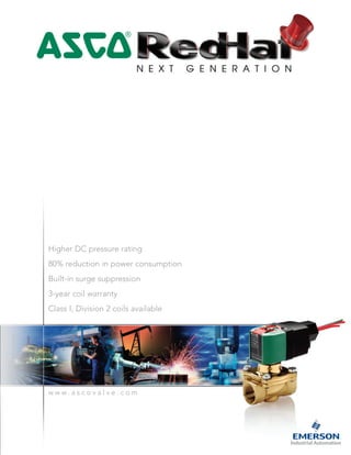
  • 1. 4 Higher DC pressure rating 80% reduction in power consumption Built-in surge suppression 3-year coil warranty Class I, Division 2 coils available w w w . a s c o v a l v e . c o m
  • 2. RedHat Next Generation is the future of solenoid valve technology, designed and manufactured to provide new capabilities. The Next Generation of solenoid valves provides lower operating cost, and represents an advancement in the performance, reliability, and ruggedness that you have come to expect from ASCO. RedHat Next Generation valves use electronics technology to manage power, providing a new standard of operation. The solenoid incorporates a power management circuit providing lower power consumption, enhanced pressure and flow ratings, and electrical surge suppression to both the solenoid and electronic controls. The new solenoid draws only 2 watts of power. A conventional solenoid with the same performance can draw as high as 17 watts of power. The savings in power usage over the installed life of the valve will lower the total cost of ownership up to 14%. The new technology accepts both AC and DC voltages without sacrificing flow or pressure specifications. DC performance has been increased by 150% to 500% from today’s industry standards, making the valves’ DC characteristics equivalent to AC pressure and flow values. This simplifies your control by eliminating the need for AC output cards, reduces wiring costs, and provides safer working environments for users operating on DC. RedHat Next Generation coils are offered in three voltage ranges covering most electrical requirements – 100-240/AC or DC, 24-99/AC or DC, or 12-24/DC. Each coil has built-in electrical surge suppression that protects the coil from external voltage spikes and eliminates inductive voltage spikes associated with conventional solenoids. An optional solenoid is available for use in Class I, Division 2 hazardous locations. ASCO RedHat Next Generation addresses many other operating characteristics that will further improve the life of your solenoid valves. These include a much lower temperature rise, and an increase in valve ambient temperature rating to 140˚F/60˚C. Because of our confidence in the rugged design of the RedHat Next Generation solenoids, ASCO is pleased to extend a 3-year warranty on the coils. Visit us online at www.ascovalve.com to see our comprehensive product portfolio. 4
  • 3. • 1/2 inch female conduit • Polyester coated aluminum conduit hub • Enclosure Types 1 through 4X • Now standard with 24 inch leads • Stainless steel nameplate • Steel clip with epoxy powder coated paint • LCP overmolded coil • Optional Class I, Division 2 coil available for hazardous locations w w w . a s c o v a l v e . c o m
  • 4. 4 w w w . a s c o v a l v e . c o m How to order Find the valve that you are looking for in the provided specifications tables. The tables contain the following information designed to help you in making your selection: Warning: Improper selection or use of products and related items in this catalog can cause death, serious injury or property damage. If you need any assistance in selecting, specifying, or ordering a valve, please contact ASCO at (800) 972-2726. As you use this catalog to select RedHat Next Generation products, note these key operating features: • Increase in DC pressure ratings to AC levels on all products (up to a 500% improvement) • Lower power operation • Voltage ranging • Built in surge suppression • Elimination of AC hum • Increase in AC and DC operating temperatures • Low solenoid temperature rise • Longer coil life due to lower operating temperatures and electrical surge suppression • Solenoid approvals to UL, CSA, and CE standards When ordering a replacement coil, select from the following: Pipe Size (ins.) Orifice Dia. (ins.) Cv Flow Operating Pressure Differential (psi) Max Fluid Temp.˚F Brass Const. Ref. Agency Stainless Steel Const. Ref. Agency Wattage AC/DC Approx. Shipping Weight (lbs.)Min. Max. AC/DC Air-Inert Gas Water Light Oil @ 300 SSU UL UL 1/2 5/8 4 0 150 150 - 180 8210P094 4 - - - 2 3.2 When ordering a valve product, specify the ASCO base catalog number (Ex. 8210P094). This number will always be 8 digits long. Choose one of the three operating voltage ranges (100-240V/50-60Hz/DC, 24-99V/50-60Hz/DC or 12-24/DC) and add it to the base catalog number (Ex. 8210P094 24-99V/50-60Hz/DC). If you want to enhance the product with one or more of the options allowed in the Optional Features Chart for that catalog number, please add the appropriate prefix or suffix (as shown): Pipe Size (ins.) Orifice Dia. (ins.) Solenoid Options Base Catalog Number Resilient Materials Other Standard Rebuild Kit ClassI, Division2Coil Brass StainlessSteel NBR FKM EPDM Neoprene OxygenService PTFE Urethane Vacuum ManualOperator MountingBracket BrassAC/DC StainlessSteel AC/DC 1/2 5/8 EE 8210P094 - V E J N - - VH MO MB 322670 - Voltage Range Valve Prefix Replacement Coil Part Number 100-240V/50-60Hz/DC - 250404-601-* 24-99V/50-60Hz/DC - 250404-602-* 12-24/DC - 250404-603-* 100-240V/50-60Hz/DC EE 250504-601-* 24-99V/50-60Hz/DC EE 250504-602-* 12-24/DC EE 250504-603-* Optional Class I, Division 2 solenoid (Ex. EE8210P094 24-99V/50-60Hz/DC) If an FKM elastomer and manual operator are required, add VMO to the back of the base catalog number. (Ex. 8210P094VMO 24-99V/50-60Hz/DC) When ordering a rebuild kit for a valve, supply the rebuild kit number as shown in the table. (Ex. 322670) When ordering a rebuild kit for a valve with a suffix, add the suffix to the appropriate standard rebuild kit. (Ex. The rebuild kit for the above valve with FKM is 322670-V) All constructions are available with prefix EE for Class I, Division 2 requirements.
  • 5. 4 w w w . a s c o v a l v e . c o m 2-Way Normally Closed 1-2 2-Way Normally Open 1-2 Dimensional Drawings 3-4 3-Way Normally Closed 5-6 3-Way Normally Open 5-6 3-Way Universal 5-6 Dimensional Drawings 7-8 4-Way 9 Dimensional Drawings 10 Engineering Information 12-18 TABLE OF CONTENTS
  • 6. 4 w w w . a s c o v a l v e . c o m1 2-Way • Two-way (2/2) Next Generation solenoid valves have one inlet port and one outlet port. • Control of air, water, light oil, and non-corrosive media. • Normally closed (opens when energized) and normally open (closed when energized) operation. • Pipe sizes – 1/4 to 2 inch. Specifications = Safety Shut-off Valve = General Purpose Valve Pipe Size (ins.) Orifice Dia. (ins.) Cv Flow Operating Pressure Differential (psi) Max Fluid Temp.˚F Brass Const. Ref. Agency Stainless Steel Const. Ref. Agency Wattage AC/DC Approx. Shipping Weight (lbs.)Min. Max. AC/DC Air- Inert Gas Water Light Oil @ 300 SSU UL UL General Service - Normally Closed 1/4 1/8 0.34 0 500 500 330 180 8262P232 1 - - - 2 2.4 1/4 5/32 0.47 0 290 250 250 180 8262P202 1 8262P220 1 2 2.4 1/4 7/32 0.72 0 145 125 120 180 8262P208 1 8262P226 1 2 2.4 1/4 9/32 0.96 0 90 85 80 180 8262P212 1 8262P230 1 2 2.4 1/4 5/16 1.5 10 1500 1500 1500 180 8223P025 2 - - - - 2 2.9 3/8 5/32 0.52 0 150 150 100 180 8263P200 3 ❍ - - - 2 1.8 3/8 9/32 0.85 0 80 80 70 180 8263P210 3 ❍ - - - 2 2.3 3/8 5/16 1.5 10 1500 1500 1500 180 8223P027 2 - - - - 2 2.9 3/8 5/8 3 0 150 150 - 180 8210P093 4 - - - 2 3.2 3/8 5/8 3 5 300 300 300 180 8210P006 4 - - - 2 3.2 1/2 3/8 3.2 25 1500 1500 1500 180 8223P003 5 - 8223P010 6 - 2 3.4 1/2 5/8 4 0 150 150 - 180 8210P094 4 - - - 2 3.2 1/2 5/8 4 0 150 150 125 180 - - - 8210P087 7 2 3.5 1/2 5/8 4 5 300 300 300 180 8210P007 4 - - - 2 3.2 3/4 5/8 4.5 0 150 150 125 180 - - - 8210P088 7 2 3.5 3/4 3/4 5 0 150 150 - 180 8210P095 7 - - - 2 3.4 3/4 3/4 5 0 3 3 - 180 8030P003 8 - - - 2 3.4 3/4 3/4 7.8 25 750 750 750 180 8223P005 9 - - - - 2 4.4 1 1 13 5 150 150 100 180 8210P004 10 - - - 2 5.4 1 1/4 1 1/8 15 5 150 150 100 180 8210P008 10 - - - 2 6.6 1 1/2 1 1/4 22.5 5 150 150 100 180 8210P022 11 - - - 2 7.7 2 1 3/4 43 5 150 125 90 180 8210P100 12 - - - 2 9.9 General Service - Normally Open 1/4 3/32 0.17 0 300 250 230 140 8262P261 13 - - - 2 2.6 1/4 1/8 0.35 0 130 110 100 180 8262P262 13 - - - 2 2.6 1/4 5/32 0.49 0 85 75 60 180 8262P263 14 - - - 2 2.6 1/4 9/32 0.96 0 30 20 20 180 8262P265 14 - - - 2 2.6 3/8 5/8 3 0 150 150 125 180 8210P033 15 - - - 2 3.4 1/2 5/8 4 0 150 150 125 180 8210P034 15 - - - 2 3.4 3/4 3/4 5.5 0 150 150 125 180 8210P035 16 - - - 2 4.2 3/4 3/4 5.5 0 2 2 - 180 8030P083 17 - - - 2 3.4 Standard: Watertight, Types 1, 2, 3, 3S, 4, and 4X. Optional: Class I, Division 2 for Hazardous Locations and Watertight, Types 3, 3S, 4, 4X. (To order, add prefix “EE” to catalog number.)
  • 7. 4 w w w . a s c o v a l v e . c o m 2 Optional Features Chart = Standard. Other options may be available. All option combinations may not be available. Please consult your local ASCO contact. Valve contains PTFE main disc; Pressure rating reduced by 25%; Pressure rating limited to 250 psi; Valve contains Nylon 11 piston. Pressure rating limited to 400 psi. Valves supplied with mounting holes in body. Pipe Size (ins.) Orifice Dia. (ins.) Base Catalog Number Resilient Materials Other Standard Rebuild Kit Brass StainlessSteel NBR FKM EPDM Neoprene OxygenService PTFE Urethane Vacuum ManualOperator MountingBracket BrassAC/DC StainlessSteel AC/DC 1/4 3/32 8262P261 - - V E J N T - - - 322777 - 1/4 1/8 8262P232 - V E J N T - - MS 322595 - 1/4 1/8 8262P262 - V E J N T - - - - 322778 - 1/4 5/32 8262P202 8262P220 V E J N T - - MS 322595 322596 1/4 5/32 8262P263 - V E J N T - - - - 322778 - 1/4 7/32 8262P208 8262P226 V E J N T - - MS 322595 322596 1/4 9/32 8262P212 8262P230 V E J N T - VH MS 322595 322596 1/4 9/32 8262P265 - V E J N T - - - - 322778 - 1/4 5/16 8223P025 - - - - - - - - - - 322815 - 3/8 5/32 8263P200 - V E J N T - - - - 322806 - 3/8 9/32 8263P210 - V E J N T - - - - 322807 - 3/8 5/16 8223P027 - - - - - - - - - - 322815 - 3/8 5/8 8210P093 - V E J N - - VH MO MB 322670 - 3/8 5/8 8210P033 - V E J N - - VH - MB 322770 - 3/8 5/8 8210P006 - V E J N - - - MO MB 322654 - 1/2 3/8 8223P003 8223P010 - - - - - - - - - 322816 322817 1/2 5/8 8210P094 - V E J N - - VH MO MB 322670 - 1/2 5/8 8210P034 - V E J N - - VH - MB 322770 - 1/2 5/8 - 8210P087 V E J N - - - MO MB - 322676 1/2 5/8 8210P007 - V E J N - - - MO MB 322654 - 3/4 5/8 - 8210P088 V E J N - - - MO MB - 322676 3/4 3/4 8210P095 - V E J N - - VH MO MB 322673 - 3/4 3/4 8030P003 - V E J N - - - MO MB 322758 - 3/4 3/4 8210P035 - V E J N - - VH - MB 322771 - 3/4 3/4 8030P083 - V E J N - - - - MB 322763 - 3/4 3/4 8223P005 - - - - - - - - - - 322818 - 1 1 8210P004 - V E J N - - - MO - 322677 - 1 1/4 1 1/8 8210P008 - V E J N - - - MO - 322680 - 1 1/2 1 1/4 8210P022 - V E J N - - - MO - 322680 - 2 1 3/4 8210P100 - V E J N - - - MO - 322682 -
  • 8. 3 4 Dimensions: inches Const. Ref. 1 0.88 0.44 0.88 0.44 .59 B C D G E F H I 2 MOUNTING HOLES M4 THREAD 0.20 DEEP 2 MOUNTING HOLES .190-32 UNF-2B 0.25 DEEP 1/2 NPT Const. Ref. 2 H C B 1/2 NPT G D E F Const. Ref. 3 .41 .38 I H C B 1/2 NPT G .81 .75 2 MOUNTING HOLES -24 UNC-2B .25 MIN THREAD DEPTH E F D Const. Ref. 4, 7, 15, 16, 17 H C B 1/2 NPT G I E F Const. Ref. 5, 6, 9 H I C B F E D 1/2 NPT Const. Ref. B C D E F G H I 1 4.00 3.04 1.97 0.79 1.19 1.56 1.87 1.41 2 4.00 3.04 1.97 0.88 1.41 2.44 1.87 - 3 4.00 3.04 1.97 0.67 1.25 1.88 1.87 1.15 4 4.00 3.04 1.97 1.28 1.84 2.75 1.87 2.28 5 4.00 3.04 1.97 1.05 2.31 - 1.87 3.03 6 4.00 3.04 1.97 1.13 2.31 - 1.87 3.13 7 4.00 3.04 1.97 1.46 2.19 2.81 1.87 2.28 8 4.00 3.04 1.97 1.44 2.13 2.81 1.87 2.28 9 4.00 3.04 1.97 1.61 3.03 - 1.87 3.60 10 4.00 3.04 1.97 2.21 3.67 3.75 1.87 - 11 4.00 3.04 1.97 2.36 4.14 4.38 1.87 3.92 12 4.00 3.04 1.97 2.75 5.52 5.06 1.87 4.72 13 4.00 3.04 1.97 0.79 1.19 1.25 1.87 1.19 14 4.00 3.04 1.97 0.79 1.19 1.56 1.87 1.19 15 4.00 3.04 1.97 1.72 2.18 2.75 1.87 2.28 16 4.00 3.04 1.97 1.88 2.57 2.81 1.87 2.28 17 4.00 3.04 1.97 0.85 1.81 2.81 1.87 2.28
  • 9. 4 4 Dimensions: inches Const. Ref. 8 H C B 1/2 NPT G I D E F Const. Ref. 10 C G 1/2 NPT D E F H B Const. Ref. 11, 12 H C B G E F I 1/2 NPT D Const. Ref. 13, 14 .67 I F D H C B 1/2 NPT 2 MOUNTING HOLES .31 DEEP FOR .164 THREAD CUTTING SCREW E
  • 10. 4 w w w . a s c o v a l v e . c o m5 3-Way • Three-way (3/2) Next Generation solenoid valves have three ports and two orifices. When one orifice is open, the other is closed. • Control of air, water, light oil, and other non-corrosive media. • Normally closed (pressure to cylinder port when energized) operation. • Normally open (cylinder port exhausts when energized) operation. • Universal operation (can function as normally open, normally closed, diverter of fluid flow, or selector of 2 fluid sources configurable by piping). • Pipe sizes – 1/4 to 3/4 inch. Specifications = General Purpose Valve. 1/4" exhaust orifice with 0.73 Cv flow; 11/32" exhaust orifice with 1.20 Cv flow; 3/32" exhaust orifice with 0.27 Cv flow. 10 psi minimum for light oils. Pipe Size (ins.) Orifice Dia. (ins.) Cv Flow Operating Pressure Differential (psi) Max. Fluid Temp.˚F Brass Const. Ref. Agency Stainless Steel Const. Ref. Agency Wattage AC/DC Approx. Shipping Weight (lbs.)Min. Max. AC/DC Air-Inert Gas Water Light Oil @ 300 SSU UL UL General Service - Normally Closed 1/4 3/32 0.17 0 205 205 205 180 8314P035 1 8314P121 1 ● 2 2.6 1/4 1/8 0.27 0 145 145 145 180 8314P036 1 - - - 2 2.6 1/4 5/64 0.12 0 232 232 232 180 8320P182 2 - - - 2 2.5 1/4 7/64 0.23 0 150 150 150 180 8320P184 2 - - - 2 2.5 1/4 5/32 0.35 0 75 75 75 180 8320P186 2 - - - 2 2.5 1/4 3/32 0.20 5 150 150 100 180 8317P035 3 - - - 2 2.7 1/4 9/32 0.80 10 200 200 200 180 8321P001 4 - - - 2 3.8 3/8 9/32 0.80 10 200 200 200 180 8321P002 4 - - - 2 3.8 3/8 5/8 2.5 10 250 250 - 180 8316P054 5 - - - 2 4.9 1/2 5/8 3.2 10 250 250 - 180 8316P064 5 - - - 2 4.9 3/4 11/16 4.8 10 250 250 - 180 8316P074 6 - - - 2 5.1 NAMUR Mount - 3/2 Normally Closed 1/4 3/32 0.12 - 150 - - 180 8320P704 8 8320P714 8 ● 2 3.2 General Service - Normally Open 1/8 7/16 0.18 - 350 350 350 180 8320P136 7 8320P146 7 ● 2 2.5 1/4 1/32 0.05 - 790 825 825 180 8320P190 2 - - - 2 2.5 1/4 5/64 0.12 0 210 210 210 180 8320P192 2 - - - 2 2.5 1/4 7/64 0.23 0 150 150 150 180 8320P194 2 - - - 2 2.5 General Service - Universal Operation 1/4 5/64 0.12 0 116 116 116 180 8320P172 2 - - - 2 2.5 1/4 7/64 0.23 0 60 60 60 180 8320P174 2 - - - 2 2.5 1/4 5/32 0.35 0 35 35 35 180 8320P176 2 - - - 2 2.5 Standard: Watertight, Types 1, 2, 3, 3S, 4, and 4X. Optional: Class I, Division 2 for Hazardous Locations and Watertight, Types 3, 3S, 4, 4X. (To order, add prefix “EE” to catalog number.)
  • 11. Pipe Size (ins.) Orifice Dia. (ins.) Base Catalog Number Resilient Materials Other Standard Rebuild Kit Brass StainlessSteel NBR FKM EPDM Neoprene OxygenService PTFE Urethane Vacuum ManualOperator MountingBracket BrassAC/DC StainlessSteel AC/DC 1/8 7/16 8320P136 8320P146 ● V E J N T - - MO/MS MB 322715 322718 1/4 1/32 8320P190 - V E J N T - - MO/MS MB 322744 - 1/4 5/64 8320P182 - V E J N T - - MO/MS MB 322722 - 1/4 5/64 8320P192 - V E J N T - - MO/MS MB 322723 - 1/4 5/64 8320P172 - V E J N T - - MO/MS MB 322721 - 1/4 3/32 8314P035 8314P121 V E - N - - - MS MB 322864 322872 1/4 3/32 8317P035 - V - - N - - - - - 322919 - 1/4 3/32 8320P704 8320P714 V E J N T - - MO/MS - 322821 322823 1/4 7/64 8320P184 - V E J N T - - MO/MS MB 322722 - 1/4 7/64 8320P194 - V E J N T - - MO/MS MB 322723 - 1/4 7/64 8320P174 - V E J N T - - MO/MS MB 322721 - 1/4 1/8 8314P036 - V E - N - - - MS MB 322864 - 1/4 5/32 8320P186 - V E J N T - - MO/MS MB 322722 - 1/4 5/32 8320P176 - V E J N T - - MO/MS MB 322721 - 1/4 9/32 8321P001 - V E - - - - - MO/MS - 322688 - 3/8 9/32 8321P002 - V E - - - - - MO/MS - 322688 - 3/8 5/8 8316P054 - V E J N - - - MO MB 322690 - 1/2 5/8 8316P064 - V E J N - - - MO MB 322690 - 3/4 11/16 8316P074 - V E J N - - - MO MB 322692 - Optional Features Chart = Standard. Other options may be available. All option combinations may not be available. Please consult your local ASCO contact. Pressure rating reduced by 25%; Upper disc is FKM; Not available with PTFE resilient materials. Pressure rating limited to 100 psi for MO constructions. 4 w w w . a s c o v a l v e . c o m 6
  • 12. 4 w w w . a s c o v a l v e . c o m7 Dimensions: inches Const. Ref.1 E F D G 0.88 0.44 0.88 0.44 0.59 I HB C 2 MOUNTING HOLES M4 THREAD 0.20 DEEP 2 MOUNTING HOLES .190-32 UNF-2B 0.25 DEEP 1/2 NPT Const. Ref. 2 JI G E D H C B 1/2 NPT 2 MOUNTING HOLES .31 DEEP FOR .164 THREAD CUTTING SCREW F Const. Ref. 3 F E .75 1.50 G D E H B C 1/2 NPT I Const. Ref. B C D E F G H I J 1 4.00 3.04 2.09 0.79 1.19 1.56 1.87 1.41 - 2 4.00 3.04 1.97 1.02 2.02 1.69 1.87 1.45 3 4.00 3.04 1.97 0.57 1.07 2.00 1.87 2.05 - 4 4.00 3.04 1.97 1.00 2.03 1.31 1.87 3.12 5 4.00 3.04 1.97 2.12 3.77 2.76 1.87 4.29 - 6 4.00 3.04 1.97 2.50 4.19 - 1.87 3.38 - 7 4.00 3.04 1.97 0.67 1.64 1.19 1.87 1.19 - 8 4.00 3.04 1.97 - - - 1.87 - -
  • 13. 4 w w w . a s c o v a l v e . c o m 8 Dimensions: inches Const. Ref. 4 G I F J D B C 0.25-20 UNC-2B 0.44 DEEP 2 PLACES H E Const. Ref. 5 F G D H E B C 1/2 NPT I Const. Ref. 6 F I D B C H 1/2 NPT E Const. Ref. 7 G E D H C B 1/2 NPT F 1 2.44 .02 1.81 3 2 1/8 PIPE THREAD 3 PLACES Ø .28 HOLE FOR MOUNTING, 2 PLACES Const. Ref. 8 3 1 2 1 3 .95 1/4 ANPT 1.91 1.26 1.75 1/4 ANPT Ø .22 x .125 DEEP FOR POSITIONING DOWEL .27 FOR M5 SCREWS, 2 PLACES .28 FOR .190-32 UNC-2A & .190-32 UNF-2A SCREWS, 2 PLACES 3.62 1.25 1.85 1/2 NPT 1 3 D B C H
  • 14. 4 w w w . a s c o v a l v e . c o m9 4-Way • Four-way, four port (4/2) and five port (5/2) Next Generation solenoid valves have one pressure port, 2 cylinder ports, and either 1 or 2 exhaust ports. • Control of air, water, light oil, and non-corrosive media. • Single solenoid operation (pressure and exhaust ports and cylinder ports alternate connection based on solenoid operation). • Pipe sizes – 1/4 to 1 inch. Pipe Size (ins.) Orifice Size (ins.) Base Catalog Number Resilient Materials Other Standard Rebuild Kit Brass StainlessSteel NBR FKM EPDM Neoprene OxygenService PTFE Urethane Vacuum ManualOperator MountingBracket BrassAC/DC 1/4 1/16 8345P001 - V - - - - - - MO - 322925 1/4 1/4 EE8551P401* EE8551P409 - - - - - - - MH/MS - - 1/4 1/4 8344P070 - V - - - - - - MO - 322696 3/8 3/8 8344P080 - V - - - - - - MO - 322700 3/8 3/8 8344P072 - V - - - - - - MO - 322697 1/2 3/8 8344P074 - V - - - - - - MO - 322697 3/4 3/4 8344P076 - V - - - - - - MO - 322698 1 3/4 8344P078 - V - - - - - - MO - 322698 Specifications Optional Features Chart = General Purpose Valve. 25 psi minimum for light oils; 3/32" exhaust orifice. * Aluminum body. = Standard. * Aluminum body. Pipe Size (ins.) Orifice Size (ins.) Cv Flow Operating Pressure Differential (psi) Max Fluid Temp.˚F Brass Const. Ref. Agency Stainless Steel Agency Wattage AC/DC Approx. Shipping Weight (lbs.)Min. Max. AC/DC Pressure Exhaust Air- Inert Gas Water Light Oil @ 300 SSU UL Const. Ref. UL General Service - Single Solenoid 1/4 1/16 0.09 0.09 10 150 150 150 180 8345P001 2 - - - 2 4.8 1/4 1/4 0.8 1.0 10 250 250 250 180 8344P070 1 - - - 2 5.2 3/8 3/8 1.4 2.2 10 250 250 250 180 8344P072 3 - - - 2 9.6 1/2 3/8 1.4 2.2 10 250 250 250 180 8344P074 3 - - - 2 9.6 3/4 3/4 5.2 5.6 10 250 250 250 180 8344P076 4 - - - 2 18.6 1 3/4 5.2 5.6 10 250 250 250 180 8344P078 4 - - - 2 18.6 General Service - 4/2 Dual Solenoid 3/8 3/8 1.4 2.2 300 300 200 180 8344P080 5 - - - 2 10.8 NAMUR Mount - 3/2, 5/2 Single Solenoid 1/4 1/4 0.86 0.86 30 150 - - 180 EE8551P401* 6 EE8551P409 6 2 4 Standard: Watertight, Types 1, 2, 3, 3S, 4, and 4X. Optional: Class I, Division 2 for Hazardous Locations and Watertight, Types 3, 3S, 4, 4X. (To order, add prefix “EE” to catalog number.)
  • 15. 4 w w w . a s c o v a l v e . c o m 10 Dimensions: inches Const. Ref. 1 J F K D H B C 1/2 NPT E G I Const. Ref. 2 F I JG D E H B C 1/2 NPT Const. Ref. 3, 4 F JK I D H E B C 1/2 NPT G Const. Ref. B C D E F G H I J K Exhaust Pipe Size 1 4.00 3.04 1.97 1.12 2.08 2.94 1.87 4.82 1.03 1.41 3/8" 2 4.00 3.04 2.09 1.00 1.75 2.06 1.87 3.00 1.09 - 1/4" 3 4.00 3.04 1.97 0.94 2.06 3.18 1.87 6.05 1.50 1.86 1/2" 4 4.00 3.04 1.97 1.31 2.86 4.12 1.87 8.25 2.10 2.12 1"
  • 16. 4 w w w . a s c o v a l v e . c o m11 Dimensions: inches Const. Ref. 6 H2 H1 L1 1/8 NPT AUX. PRESSURE PORT L2 3 1 W 4.00 3.04 4.00 3.04 Series 8551 NPT 1/4 L1 4.96 L2 6.50 H2 3.97 H1 1.57 W 1.77 Optional Manual Operators Add Suffix Description MO 1 20 Push and turn to lock with flat head screwdriver slot MI 1 20 Momentary push in with flat head screwdriver slot MH 1 20 Momentary push in by hand MS 1 20 Push and turn to lock by hand 42 .95 (24) 1.26(32) 8551 NAMUR Footprint Const. Ref. 5 1.87 1.19 1.96 1.56 2.68 3.04 4.00 .83 1.86 1.75 3.09 6.06 1/2 PIPE THREAD 1.50 2.62 1.06 PIPE THREAD 3 PLACES Ø.34 2 HOLES FOR MOUNTING 1.62 1.16 3.18 1.56 1.88 3.12 2.13 1.87 P E B A P SOL A E SOL B
  • 17. 4 w w w . a s c o v a l v e . c o m 12 Engineering Section Principles of Operation A solenoid valve is a combination of two basic functional units: • A solenoid (electromagnet) with its core. • A valve body containing one or more orifices. Flow through an orifice is controlled by the movement of the core when the solenoid is energized or de-energized. The core is enclosed in a sealed tube, providing a compact, leaktight assembly. For additional information on different types and functions of solenoid valves including direct acting, internally pilot operated valves, two-way, three-way, and four-way valves please visit our website at www.ascovalve.com. Note: The 100-240 voltage range is also suitable for battery charging circuits designed around a 125/DC nominal voltage range. Voltage Range Minimum Voltage Maximum Voltage 100-240V/50 or 60Hz/DC 85 264 24-99V/50 or 60Hz/DC 20.4 109 12-24/DC only 10.4 26.4 Solenoids All RedHat Next Generation solenoid valves are rated for continuous duty under the operating conditions outlined within this section. Coil Operating Voltage Ranges All coils are designed for industrial operating voltages and can be used on the following voltage ranges: Core Coil Body The coils with voltage ranges of 100-240 and 24-99 have three lead wires, 24 inches long (2 red for power input, and one green lead for grounding where necessary). These two versions are not polarity sensitive. The coil with a voltage range of 12-24/DC has 3 lead wires, one red, one black, and one green. This coil is polarity sensitive. The red lead is the positive, black is the negative, and green is the ground wire. This solenoid is also polarity protected. Reversing the polarity will not damage the coil, but the coil will not function until the correct polarity is applied. Lead wire - UL and CSA listed 600 volt leads, 6 strand, 18awg, PE coated Overmold LCP Bobbin-LCP Magnet wire - Class H insulation
  • 18. 4 w w w . a s c o v a l v e . c o m13 Electrical Specifications Inrush Current: The power source, wiring, and output device used need to have surge ratings equal to or greater than the inrush current value (appropriate to the voltage range) specified in the table below. Power Consumption Holding Current: The power source, wiring, and output device used need to have continuous current ratings equal to or greater than the holding current value (appropriate to the voltage range) specified in the table below. Leakage Currents: The leakage current is defined as a current that is supplied from an output device when the device is in its off or de-activated state. Operation of Next Generation coil in a system that utilizes supervisory currents is not recommended. 2 Watt Electronic Coils Type Maximum Ambient Temperature 140˚F Maximum Cycle Rate 1 Operation/Second Standard Coil Class of Insulation H The Next Generation solenoid nominal power rating is 2 watts. Depending on the input voltage applied, the actual power rating may vary. Please use the charts below to determine your actual power rating. The advanced technology used in the Next Generation coil includes electronic circuitry which may limit the compatibility with certain control system components. The following issues need to be considered when specifying an output card or device to operate the Next Generation coil. An initial inrush current spike is drawn by the Next Generation coil. This inrush spike is 72 msec in duration, which is sufficient time for the core to reach the plugnut. The electrical requirement then drops to the holding value. 1.4 1.5 1.6 1.7 1.8 1.9 2.0 24 62 99 Voltage Input 1.4 1.5 1.6 1.7 1.8 1.9 2.0 100 170 240 Voltage Input 1.4 1.5 1.6 1.7 1.8 1.9 2.0 12 18 24 Voltage Input Version 100-240/50-60Hz Version 24-99/50-60Hz Version 12-24/DC Watts Watts Watts Watt Rating Inrush Current Rating Coil Version Peak Inrush Current (Amps) 12-24/DC 3.2 24-99/50-60Hz/DC 1.4 100-240/50-60Hz/DC 0.32 Maximum Duration = 72 ms Holding Current Rating Coil Version Input Voltage Average Holding Current (Amps) Average Holding Volt-Amps (VA) 12-24/DC 12 0.340 4.0 24 0.250 6.0 24-99/50-60Hz/DC 24 0.170 4.0 99 0.100 10.0 100-240/50-60Hz/DC 100 0.040 4.0 240 0.032 7.5 Maximum Leakage Current 3 mA
  • 19. 4 w w w . a s c o v a l v e . c o m 14 The Next Generation solenoid coil is fully encapsulated using Dupont™ Zenite® Liquid Crystal Polymer resin (LCP). Zenite (LCP) is a thermoplastic polyester resin which exhibits several advantages over other thermo- plastics. The advantages include excellent resistance to a wide range of organic solvents and automotive fluids*, resistance to impact, and long term retention of properties at continuous-use temperatures. *Chemical resistance of Zenite LCP may not be suitable for all applications. Zenite LCP is not suitable for caustic solution. Please consult ASCO for appropriate product solutions. Zenite is a registered Trademark of Dupont Co. Solenoid Enclosures Type 1 General Purpose – Intended for indoor use, primarily to provide protection for enclosed parts in locations without unusual service conditions. DIN-type terminals meeting ISO 4400 and DIN Standard 43650. Type 2 Dripproof – Intended for indoor use, primarily to provide protection against limited amounts of falling water or dirt. Type 3 Raintight, Dusttight, and Sleet (Ice) Resistant – Intended for outdoor use, primarily to provide protection against wind-blown dust, rain, and sleet; undamaged by the formation of ice on the enclosure. Type 3S Raintight, Dusttight, and Sleet (Ice) Resistant – Intended for outdoor use, primarily to provide protection against wind-blown dust, rain, and sleet; external mechanism remains operable when ice laden. Type 3R Rainproof, Sleet (Ice) Resistant – Intended for outdoor use, primarily to provide protection against falling rain and sleet; undamaged by the formation of ice on the enclosure. Type 4 Watertight and Dusttight – Intended for indoor or outdoor use to provide protection against splashing water, water seepage, falling or hose-directed water, and severe external condensation; undamaged by the formation of ice on the enclosure. Type 4X Watertight, Dusttight, and Corrosion Resistant – Same as Type 4 but provides additional protection to resist corrosion. Class I, Division 2 for Hazardous Locations/Watertight – Meets Types 1 through 4X and is UL listed and CSA certified for Class I, Division 2, Groups A, B, C, and D and Class II, Division 2, Groups F and G. Operating temperature code T4A (120˚C). General Purpose/Watertight – Intended for indoor and outdoor use and provides protection classifications from NEMA types 1 through 4X.
  • 20. 4 w w w . a s c o v a l v e . c o m15 Valve Specifications Minimum Operating Pressure Differential The minimum operating pressure differential is required to fully open the valve and keep it open. For 2-way valves with a floating diaphragm, the valve may start to close below the minimum pressure differential. For 3 and 4-way valves, the minimum operating pressure differential is measured between the pressure and exhaust ports and must be maintained through the operating cycle to ensure complete transfer from one position to the other. Note: Hung diaphragm constructions do not require a minimum pressure differential, however, may not yield maximum flow rates at low-pressure differentials. Maximum Operating Pressure Differential (MOPD) The maximum operating pressure differential refers to the maximum difference in pressure between the inlet and outlet ports, against which the solenoid can safely operate the valve. If the pressure at the outlet is not known, it is safest to regard the supply pressure as the MOPD. Minimum Ambient Temperature The nominal limitation of 32˚F (0˚C) is advisable for any valve that might contain moisture (water vapor). Where freezing water is not a factor, the minimum ambient temperature of the products listed in this catalog is 14˚F (-10˚C). Special constructions are available with low temperature elastomers to provide service at -40˚F (-40˚C) ambient temperatures. Consult ASCO for more information. Maximum Ambient Temperature The maximum ambient temperature is 140˚F (60˚C). This limit is based on continuous energization with the maximum fluid temperatures as shown on each catalog page. Response Time Response time from fully closed to fully open or vice versa depends on valve size, operating mode, fluids, temperature, inlet pressure, and pressure drop. The response times for Next Generation are defined as: Small direct acting valves – 10 to 60 msec Large direct acting valves – 25 to 90 msec Internally pilot operated valves: - Small diaphragm types – 20 to 100 msec - Large diaphragm types – 80 to 150 msec - Small piston types – 80 to 150 msec - Large piston types – 105 to 200 msec Operation on liquids has relatively little effect on small direct acting valves, however, response times of large direct acting and internally piloted valves may be lengthened by 50% to 100%. Viscosity All valves with a pressure rating for light oil are designed for use with oils rated for a maximum of 300 SSU's with the following exceptions: Series 8314, 8317, 8321 – 45 SSU Series 8345 – 50 SSU
  • 21. 4 w w w . a s c o v a l v e . c o m 16 Resilient Material Selection NBR (Buna "N", Nitrile) – NBR is commonly referred to as a nitrile rubber and is the standard synthetic elastomer for accomplishing resilient-type seating or sealing in ASCO valves. It has excellent compatibility for most air, water, and light oil applications. It has a useful temperature range of 0°F to 180°F (-18°C to 82°C). FKM (Viton® /Fluorel® , etc.) – FKM is a fluorocarbon elastomer primarily developed for handling such hydrocarbons as jet fuels, gasolines, solvents, etc., which normally cause detrimental swelling to NBR. FKM has a high temperature range similar to EPDM, but more resistant to “dry heat.” FKM has a wide range of chemical compatibility. It has a useful temperature range of 0°F to 350°F (-18°C to 177°C). EPDM (Ethylene Propylene) – EPDM is selected for applications above the NBR temperature range, such as handling hot water and steam. Ethylene propylene has an extremely wide range of fluid compatibility, but has the distinct disadvantage that it cannot be used with petroleum-based fluids or contaminated fluids (such as lubricated air). It has a useful temperature range of -10°F to 300°F (-23°C to 149°C). CR (Neoprene) – CR is principally used as an external seal in refrigeration applications. It is also utilized for oxygen service. It has a useful temperature range of 0°F to 180°F (-18°C to 82°C). Oxygen Service – All valve parts are degreased and blacklight inspected for cleanliness. They are assembled and tested in a clean area using oil-free air or nitrogen; helium mass spectrometer tested for external leakage. The pipe connections are sealed with plugs, and each valve is tagged certifying testing. All valves are shipped in sealed bags. PTFE (Teflon® , Rulon) – PTFE and PTFE with fillers are considered more a plastic than a resilient-type material. They are virtually unattacked by any fluid. Their temperature usage has ranges from discs for cryogenic valves to discs for steam valves. They are not easily fabricated and are known to have “cold flow” characteristics which may contribute to objectionable leakage, particularly on gases. Urethane – Urethane is primarily used on high pressure valves, and/or for long life applications, because of its high strength and abrasion resistance. The physical and chemical properties of urethane vary depending on whether the compound is polyester or polyether based. Urethane has a wide range of chemical resistance including alcohols, non-aromatic compounds, ethers, edible fats and oils, hydraulic fluid, and water. It has a useful temperature range of -90ºF to 200ºF for ethers, and -30ºF to 200ºF for esters. Polyester based Urethanes in contact with moisture should be limited to a maximum temperature of 140ºF. Viton & Teflon are registered Trademarks of DuPont Co. Fluorel is a registered Trademark of 3M. Series Number Const. Ref. Manual Operator Suffix Manual Operator Type Illustration Number 8030 8 MO Maintained 3 8210 4, 7, 10, 11, 12 MO Maintained 2 8262 1 MS Maintained 6 8314 1 MS Maintained 6 8316 5, 6 MO Maintained 2 8320 2 MO Momentary 1 8320 2 MS Maintained 6 8321 4 MO Momentary 1 8321 4 MS Maintained 3 8344 1, 3, 4 MO Maintained 2 8345 2 MO Maintained 5 Manual Operators Manual operators are provided to operate the valves manually when electric actuation is not provided. There are two basic types of manual operators, momentary and maintained. To determine which type of manual operator is available for your valves, please see the Optional Features Chart on the relevant valve catalog page. Once it is determined that the subject valve can accommodate a manual operator, the chart below will tell you the type of manual operator. The chart also references the relevant cutaway illustration.
  • 22. 4 w w w . a s c o v a l v e . c o m17 Valve Parts in Contact with Fluids Catalog Number Body Seals and Discs Disc Holder Core Guide Springs Shading Coil Stem 8030P003 Brass NBR - - 302 Stainless Steel - - 8030P083 Brass NBR - - 302 Stainless Steel - - 8210P004 Brass NBR - - 302 Stainless Steel - - 8210P007 Brass NBR - - 302 Stainless Steel - - 8210P008 Brass NBR - - 302 Stainless Steel - - 8210P022 Brass NBR PA - 302 Stainless Steel - - 8210P033 Brass NBR PA - 302 Stainless Steel - - 8210P034 Brass NBR PA - 302 Stainless Steel - - 8210P035 Brass NBR PA - 302 Stainless Steel - - 8210P087 304 Stainless Steel NBR - - 302 Stainless Steel - - 8210P088 304 Stainless Steel NBR - - 302 Stainless Steel - - 8210P093 Brass NBR - - 302 Stainless Steel - - 8210P094 Brass NBR - - 302 Stainless Steel - - 8210P095 Brass NBR - - 302 Stainless Steel - - 8210P100 Brass NBR - - 302 Stainless Steel - - 8223P003 Brass NBR, PA, PTFE - - 302 Stainless Steel Copper - 8223P005 Brass NBR, PA, PTFE - - 302 Stainless Steel Copper - 8223P010 304 Stainless Steel PTFE, NBR - - 302 Stainless Steel Silver - 8223P025 Brass NBR, PA, PTFE - - 302 Stainless Steel Copper - 8223P027 Brass NBR, PA, PTFE - - 302 Stainless Steel Copper - 8262P202 Brass NBR - - 302 Stainless Steel Copper - 8262P208 Brass NBR - - 302 Stainless Steel Copper - 8262P212 Brass NBR - - 302 Stainless Steel Copper - 8262P220 304 Stainless Steel NBR - - 302 Stainless Steel Silver - 8262P226 304 Stainless Steel NBR - - 302 Stainless Steel Silver - 8262P230 304 Stainless Steel NBR - - 302 Stainless Steel Silver - 8262P232 Brass NBR - - 302 Stainless Steel Copper - 8262P261 Brass UR - - 302 Stainless Steel Copper PA 8262P262 Brass NBR - - 302 Stainless Steel Copper PA 8262P263 Brass NBR - - 302 Stainless Steel Copper PA 8262P265 Brass NBR - - 302 Stainless Steel Copper PA 8314P035 Brass NBR, FKM - CA 302 Stainless Steel Copper - 8314P036 Brass NBR, FKM - CA 302 Stainless Steel Copper - 8314P121 303 Stainless Steel NBR, FKM - CA 302 Stainless Steel Silver - 8316P054 Brass NBR CA CA 302, 17-7PH Stainless Steels Copper - 8316P064 Brass NBR CA CA 302, 17-7PH Stainless Steels Copper - 8316P074 Brass NBR CA CA 302, 17-7PH Stainless Steels Copper - 8317P035 Brass NBR, FKM, CR - CA 302, 17-7PH Stainless Steels Copper - 8320P172 Brass NBR CA CA 302, 17-7PH Stainless Steels Copper - 8320P174 Brass NBR CA CA 302, 17-7PH Stainless Steels Copper - 8320P176 Brass NBR CA CA 302, 17-7PH Stainless Steels Copper - 8320P182 Brass NBR CA CA 302, 17-7PH Stainless Steels Copper - 8320P184 Brass NBR CA CA 302, 17-7PH Stainless Steels Copper - 8320P186 Brass NBR CA CA 302, 17-7PH Stainless Steels Copper - 8320P192 Brass NBR CA CA 302, 17-7PH Stainless Steels Copper - 8320P194 Brass NBR CA CA 302, 17-7PH Stainless Steels Copper - 8321P001 Brass NBR CA CA 302 Stainless Steel Copper - 8321P002 Brass NBR CA CA 302 Stainless Steel Copper - 8344P070 Brass NBR CA CA 302, 17-7PH Stainless Steels Copper - 8344P072 Brass NBR CA CA 302, 17-7PH Stainless Steels Copper - 8344P074 Brass NBR CA CA 302, 17-7PH Stainless Steels Copper - 8344P076 Brass NBR CA CA 302, 17-7PH Stainless Steels Copper - 8344P078 Brass NBR CA CA 302, 17-7PH Stainless Steels Copper - 8345P001 Brass NBR, FKM - CA 302, 17-7PH Stainless Steels Copper - Note: All core tubes are 305 stainless steel and all cores and plugnuts are 430F stainless steel.
  • 23. 4 w w w . a s c o v a l v e . c o m Approvals Approval Listing Code and Information UL, CSA, and CE listings are indicated on each series of valves in this catalog. Listing codes and other information follow in this section. Agency Valve Classifications and Code Reference Solenoid Recognized Components – Solenoids in this category are intended for use as factory-installed components of equipment where final acceptability must be determined by UL or CSA. ASCO RedHat Next Generation solenoids are listed in the UL recognized component index under Guide No. YSYI2 for ordinary locations and VAPT for hazardous locations. General Purpose Valves – Normally open or normally closed valves intended to control the fluid flow, but not to be depended upon to act as safety valves. This is a UL and CSA classification and is not intended to indicate valve service or application. General purpose valves are listed in UL index under Guide No YIOZ or YIOZ2 for ordinary locations and YTSX or YTSX2 for hazardous locations. Safety Shutoff Valves – Normally closed valves of the “on” and “off” type, intended to be actuated by a safety control or emergency device, to prevent unsafe fluid delivery. They may also be used as General Purpose valves. Multiple port valves may be designated as safety shutoff valves only with respect to the normally closed port. This is a UL and CSA classification. Safety shutoff valves are listed in UL index under Guide YIOZ or Y1OZ2 for ordinary locations and YTSX or YTSX2 for hazardous locations. ^ Underwriters Laboratories (UL) UL429, “Electrically Operated Valves.” UL1604, “Electrical Equipment for use in Class I and II, Division 2 and Class III hazardous classified locations.” % Canadian Standards Association (CSA) Standard C22.2 No. 139, “Electrically Operated Valves.” Standard C22.2 No. 213, “Electrical equipment for use in Class I, Division 2 hazardous locations.” ) European Directive (CE) The council of the European Communities under the treaty establishing the European Economic Community (EEC) adopted into law a series of directives to harmonize technical standards. Solenoid valves are controlled by: Council Directive # Machinery 89/392/EEC EMC 89/336/7EC Low Voltage 72/23/EEC PED 97/23/EC (Electromagnetic Capability) ASCO RedHat Next Generation valves comply with these directives, through third party or self-certification. The General Purpose/Watertight coils each bear the CE approval mark on the coil. (Pressure Equipment Directive) Quality Assurance ASCO’s Quality Assurance Program meets all the requirements of ISO9001-2000. ASCO can provide product from 17 ISO-certified facilities around the world. 18
  • 24. ASCO Valve, Inc. • 800.972.2726 • www.ascovalve.com 09/09 - V7381R6 France Tel (33) 1-47-14-32-00 Germany Tel (49)-7237-9960 United Kingdom Tel (44) 1695-713600 Australia Tel (61) 2-9-451-7077 China Tel (86-28) 8662-8833 Japan Tel (81) 798-65-6361 Singapore Tel (65) 6556-1100 Brazil Tel (55) 11-4208-1660 Mexico Tel (52-55) 5809-5640 Canada Tel 519-758-2700