More Related Content
Similar to Penberthy (20)
More from SHORTBUS101 (12)
Penberthy
- 1. Penberthy Multiview™
Magnetic Liquid Level Gauges
Copyright © 2009 Tyco Flow Control. All rights reserved. PENMC-0669-US-0907
Keystone is either a trademark or registered trademark of Tyco International Services AG or its affiliates in
the United States and/or other countries. All other brand names, product names, or trademarks belong to
their respective holders.
Flow Control
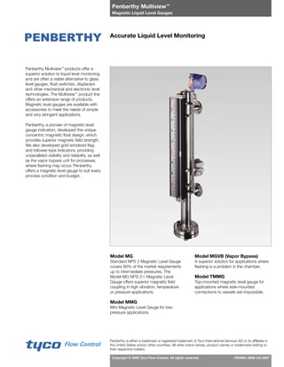
Accurate Liquid Level Monitoring
Penberthy is either a trademark or registered trademark of Tyco International Services AG or its affiliates in
the United States and/or other countries. All other brand names, product names or trademarks belong to
their respective holders.
Penberthy Multiview™
products offer a
superior solution to liquid level monitoring
and are often a viable alternative to glass
level gauges, float switches, displacers
and other mechanical and electronic level
technologies. The Multiview™
product line
offers an extensive range of products.
Magnetic level gauges are available with
accessories to meet the needs of simple
and very stringent applications.
Penberthy, a pioneer of magnetic level
gauge indication, developed the unique
concentric magnetic float design, which
provides superior magnetic field strength.
We also developed gold anodized flag-
and follower-type indicators, providing
unparalleled visibility and reliability, as well
as the vapor bypass unit for processes,
where flashing may occur. Penberthy
offers a magnetic level gauge to suit every
process condition and budget.
Model MG
Standard NPS 2 Magnetic Level Gauge
covers 80% of the market requirements
up to intermediate pressures. The
Model MG NPS 21
⁄2 Magnetic Level
Gauge offers superior magnetic field
coupling in high vibration, temperature
or pressure applications.
Model MMG
Mini Magnetic Level Gauge for low-
pressure applications.
Model MGVB (Vapor Bypass)
A superior solution for applications where
flashing is a problem in the chamber.
Model TMMG
Top-mounted magnetic level gauge for
applications where side-mounted
connections to vessels are impossible.
- 2. Penberthy Multiview™
Magnetic Liquid Level Gauges
Copyright © 2009 Tyco Flow Control. All rights reserved. PENMC-0669
2
Penberthy Multiview™ Follower-type and Flag-type Indicators
Follower-type Indication
In MG Follower-type models, the unit
consists of a hermetically sealed tube in a
protective view housing. Within this tube is
a gold (other colors are available) anodized
aluminum follower which will mirror level
changes in the process tank. This entire
assembly is attached to the standpipe,
where the follower is magnetically coupled
with the float.
Because the follower and float are
magnetically linked, liquid level changes
in the process tank will cause the float
and the follower to rise and fall in unison.
The result is a precise indication of liquid
level within the vessel. The anodized gold
follower is designed to withstand extreme
heat up to 800°F [427°C] without adverse
wear and discoloration.
Follower-type monitoring is suitable for
most applications, except where violent
changes in level or high vibration can
cause the follower to decouple from the
float. In these types of applications,
flag-type indication is recommended.
Flag-type Indication
MG Flag-type models provide an
enhanced secure link between indicator
and float. The view housing is sealed and
consists of a single-column assembly
of aluminum flags within an extruded
aluminum channel. These flags are
anodized with black on one side and
gold on the other. Each flag houses a
small magnet and is assembled on an
individual axle.
As the float in the standpipe rises and
falls, the magnetic interaction between the
float and flag magnets causes the flags
to rotate 180°. These changes are shown
through contrasting colors – black above
and gold below the liquid level. To help
ensure trouble-free operation, our flags
are magnetically interlocked and utilize
mechanical stops. This is designed to
prevent over-rotation.
Penberthy’s redundant axle system helps
prevent binding, with each flag allowed
to rotate on the axle and each axle free
to rotate in the channel. This method of
indication is accurate regardless of the
speed of process level change or vibration.
- 3. Penberthy Multiview™
Magnetic Liquid Level Gauges
Copyright © 2009 Tyco Flow Control. All rights reserved. PENMC-0669
3
MG Model
The standard MG NPS 2 model utilizes a
Schedule 10 pipe (1) with a conventional
corrugated magnetic-ring float design.
The MG NPS 2½ can utilize a Schedule
10 or Schedule 40 pipe with a concentric
magnetic float design for applications
in higher vibration, along with added
internal support for higher-pressure and
higher-temperature applications. All
metallic standpipe designs are rated to
the ANSI / ASME Boiler and Pressure
Vessel Codes and ANSI / ASME B31.1 /
B31.3. This makes them ideal for use in
all kinds of storage and pressure vessel
applications, including those in the most
extreme-duty conditions. In addition,
we offer polymer versions constructed
of 2" Schedule 40 pipe for low-pressure
applications, where cost control and
corrosion resistance are necessary.
Features and Benefits
• Connection Versatility – A wide
variety of connections is available:
weld neck flanges, lap-joint flanges,
weldolets, threadolets, sockolets, 3000-
lb. threaded process couplings and
other plumbing options. Extruded tee
allows for full-penetration welding on all
side connections for Schedule 10 pipe.
• Process Compatibility – A wide
variety of material or lining options to
meet most process applications.
• Code Design – Meets the design
requirements of ANSI / ASME Boiler and
Pressure Vessel Code ASME B31.1.
Remote Control and Indication• –
A wide variety of switches and
transmitters is available for mounting
on the MG.
1
2
3
4
5
6
Illustration Key
1. Standpipe
2. Tank Connection
3. Clamp
4. Follower or Flag Indicator
5. Indicator Scale
6. Magnetic Float
Construction Material
316 / 316L SS
Alloy-20
Monel®
Titanium
Hastelloy-C
Float Minimum Specific Gravity
Float Material Minimum Specific Gravity
316 / 316L SS 0.49
Titanium 0.37
Monel®
0.51
Alloy-20 0.47
Hastelloy-C 0.53
Other Consult Sales
Standard Standpipe Lengths
Overall [mm] Vessel Centers [mm]
Side Connection Minimum 207
⁄16" [519] 41
⁄4" [108]
Maximum 25915
⁄16" [6577] 236" [5994]
End Connection Minimum 207
⁄16" [519] 41
⁄4" [108]
Maximum 25415
⁄16" [6475] 236" [5994]
Temperature Ranges
Float /
Standpipe
Material
Minimum
Temp.
°F [°C]
Maximum
Temp.
°F [°C]
Metallic -325°F [-198°C] 750°F [400°C]
Pressure Ratings (Float Limited)
Float / Standpipe
Material
Standpipe Schedule 10
psig@100°F [kPag@38°C]
Standpipe Schedule 40
psig@100°F [kPag@38°C]
Float @ 100°F
ANSI / psig
316 / 316L SS 1600 [11034] 2800 [19310] 900# / 2160
Titanium 915 [6310] 1590 [10966] 900# / 1800
Monel® 1500 [10345] 2600 [17931] 900# / 1800
Alloy-20 1400 [9655] 2500 [17241] 900# / 1800
Hastelloy-C 1800 [12414] 3100 [21379] 900# / 2250
Other Consult Sales Consult Sales Consult Sales
- 4. Penberthy Multiview™
Magnetic Liquid Level Gauges
Copyright © 2009 Tyco Flow Control. All rights reserved. PENMC-0669
4
MG Model
Construction Material
304 / 304L SS
316 / 316L SS
Alloy-20
Monel®
Titanium
Hastelloy-C
PVC
CPVC
PVDF
Tefzel® Lined
Halar® Lined
Pressure Ratings (Float Limited)
Float / Standpipe
Material
Standpipe Schedule 10
psig@100°F [kPag@38°C]
Standpipe Schedule 40
psig@100°F [kPag@38°C]
Float @ 100°F
ANSI / psig
316 / 316L SS 1270 [8756] 2200 [15168] 900# / 2160
304 / 304L SS 1270 [8756] 2200 [15168] 900# / 1800
Titanium 915 [6309] 1580 [10894] 900# / 1800
Monel® 1400 [9655] 2430 [16754] 900# / 1800
Alloy-20 1240 [8549] 2140 [15444] 900# / 1800
Hastelloy-C 1480 [10204] 2560 [17651] 900# / 2250
PVC — — 3100 [21379] 150 psig
CPVC — — — — 150 psig
Other Consult Sales Consult Sales Consult Sales
Metallic standpipe based on: P =
2 S Et
D-2yt
Stresses from ANSI B31.1 or ASME Section II-D
These pressure ratings assume that all fittings are equal to or exceed the standpipe ratings.
For Halar®
/ Tefzel®
lining and other float materials, contact your sales representative for details.
Float Minimum Specific Gravity
Float Material Minimum Specific Gravity
316 / 316L SS 0.49
304 / 304L SS 0.49
Titanium 0.37
Monel® 0.51
Alloy-20 0.47
Hastelloy-C 0.53
PVC 0.79
CPVC 0.86
Other Consult Sales
Stated specific gravity is for metallic ANSI 150 Schedule 10 extended-length float, except for polymers.
Standard Chamber Lengths
Overall [mm] Vessel Centers [mm]
Side Connection Minimum 207
⁄16" [519] 41
⁄4" [108]
Maximum 25815
⁄16" [6577] 236" [5994]
End Connection Minimum 207
⁄16" [519] 41
⁄4" [108]
Maximum 25415
⁄16" [6475] 236" [5994]
Consult your sales representative for lengths outside of stated maximum or minimum.
Temperature Ranges
Float / Standpipe Material Minimum Temp. °F [°C] Maximum Temp. °F [°C]
Metallic -325°F [-198°C] 750°F [400°C]
PVC -20°F [-28°C] 140°F [60°C]
CPVC -20°F [-28°C] 200°F [93°C]
Note: Specification data subject to change without notice.
Follower-type
with Transmitter
and Switch
Flag-type
with Transmitter
and Switch
- 5. Penberthy Multiview™
Magnetic Liquid Level Gauges
Copyright © 2009 Tyco Flow Control. All rights reserved. PENMC-0669
5
1
4
3
5
2
7
6
FlashingVaporsBypassFloat
MGVB (Vapor Bypass) Model
The Multiview™
Vapor Bypass is an
example of Penberthy’s innovation
in magnetic level gauge design and
addresses processes where flashing may
occur. Many other magnetic gauges can
fail in these types of processes. When
flashing occurs, the vapor buildup beneath
the float cannot escape quickly enough
due to the limited clearance between
the float and the chamber wall. This
causes the float to rocket to the top of the
chamber where it is crushed or damaged.
The Multiview™
Vapor Bypass features a
large chamber – a unique cage system
which confines the float to one side of
the chamber. This allows the maximum
area for vapor to bypass the float, helping
ensure proper magnetic coupling to the
indicator.
Features – MGVB (Vapor Bypass)
Larger chamber and unique internal•
float cage
Magnetically interlocked flag-type•
indication
Custom-weighted magnetic float•
Designed in accordance with•
ASME B31.3
Easy installation•
Virtually maintenance-free•
Optional transmitter or switches•
Typical Applications
Light Hydrocarbons•
Liquid Nitrogen•
Propane•
Methane•
Carbon Dioxide•
Anhydrous Ammonia•
(or any pressure-liquified gas)
Technical Data
Material: 4 NPS Schedule 40 pipe
Size range: Vessel centers are
4.25 to 236
[108mm to 5994mm]
Specific gravity: 0.47
Pressure rating: 300# ANSI
Temperature
range: -325°F to 750°F
[-198°C to 400°C]
Refer to previous pages in this bulletin for
other features shared with the
standard Multiview™.
Illustration Key
1. Standpipe
2. Vessel Connections
3. Internal Guide Cage
4. Clamp
5. Magnetic Float
6. Flag Indicator
7. Indicator Scale
- 6. Penberthy Multiview™
Magnetic Liquid Level Gauges
Copyright © 2009 Tyco Flow Control. All rights reserved. PENMC-0669
6
TMMG (Top-mount Magnetic Gauge) Model
When side-mounted level monitoring is not
feasible, we offer the Multiview™
TMMG.
The TMMG features the same trouble-
free method of operation as a standard
Multiview™
Magnetic Liquid Level Gauge.
A stilling well is recommended to help
protect both the float and the tube from
damage, the primary cause of top-mount
failure. In vessels where large particulates
can become trapped between float and
stilling well, our unique guide system limits
the contact area, virtually eliminating the
possibility of particulates clogging and
hindering float.
Features – TMMG Top-Mounting
The TMMG float is located in the
containment vessel, while the magnet
assembly is at the opposite end of a
tube in the standpipe. As the float level
changes, so does the magnetic position.
The level change is visually conveyed to
the operator via the indicator mounted to
the standpipe.
Options – TMMG Top-Mounting
Both point-level and continuous•
electronic level indication can be added
by using Penberthy’s third-party-
approved switches and transmitters.
Optional stilling well can be installed•
for additional protection of both float
and tube.
Unique guide system can be•
added to help minimize the risk of
particulate matter / crystallization
affecting float operation.
Float Minimum Specific Gravity
Float Diameter
[mm]
Minimum
Specific Gravity
3.5 [89] 0.50
4.5 [114] 0.32
6 [152] 0.21
8 [203] 0.20
10 [254] 0.15
Specific gravities are based upon multiple ANSI
150# Titanium floats. Your actual minimum
specific gravity will be application-based.
Construction Material
Standpipe Float
304 / 304L SS • •
316 / 316L SS • •
Titanium • •
Monel® • •
Inconel®625 • •
Alloy-20 • •
Hastelloy-C • •
Other Consult Sales
Minimum Vessel Opening Requirements
Float Diameter
[mm]
Minimum Flange
Connection Required
3.5 [89] 4
4.5 [114] 5
6 [152] 6
8 [203] 8
10 [254] 10
Minimum connection sizes assume the use of a
Schedule 10 stilling well equal to the flange size.
If a higher schedule or Penberthy’s guide system
is used, consult your sales representative.
Guide
System
TMMG
- 7. Penberthy Multiview™
Magnetic Liquid Level Gauges
Copyright © 2009 Tyco Flow Control. All rights reserved. PENMC-0669
7
MMG (Mini Magnetic Gauge)
In applications where monitoring will
operate at or near ambient temperature,
the Mini Magnetic Gauge (MMG) is
recommended. This system performs well
in applications such as air conditioning,
refrigeration, wastewater treatment,
oil / chemical storage, skid systems
manufacturing, boiler feedwater tanks and
filter / tank manufacturing.
The MMG is constructed using NPS 1
Schedule 10 standpipe with flag-type
level indication. Because of the smaller
float diameter, the MMG features a
conventional six-magnet configuration
with a magnetic field similar to other
Multiview™
models.
Features –
MMG (Mini Magnetic Gauge)
MMGs feature a nominal 1 Schedule 10
standpipe with flag-type level indication.
Because of the smaller float diameter, the
MMG features a conventional six-magnet
configuration with a magnetic field similar
to other Multiview™
models. The MMG
carries a true 150# ANSI rating. Standard
construction material for the standpipe
is 316 / 316L SS, although 304 / 304L
may also be specified. Float construction
material is 316 / 316L SS.
Options –
MMG (Mini Magnetic Gauge)
1-amp point-level switch available for•
level control.
Penberthy’s standard, third-party-•
approved transmitter can be added for
continuous level monitoring.
Technical Data
Materials: Standpipe:
316 / 316L SS
304 / 304L SS
Float: 316 SS
Standpipe
diameter: Nominal 1 Schedule 10
Minimum
specific gravity: Standard Length: 0.70
Extended Length: 0.65
Maximum
C-C dimension
(indication
length): 2225
⁄8 * [5655 mm]
Pressure rating: 150# ANSI (PN 16 / 25)
Temperature
range: Determined by chosen
design of flag-type
indicator
* Indication lengths greater than this require a
staggered bridle arrangement. Consult your sales
representative for additional information.
Technical data subject to change without notice.
MMG
- 8. Penberthy Multiview™
Magnetic Liquid Level Gauges
Copyright © 2009 Tyco Flow Control. All rights reserved. PENMC-0669
8
Switches and Transmitter Options
Both point-level control and/or continuous
level measurement are available with the
Multiview™
. These options can be ordered
with your magnetic gauge or can be
added to existing units.
MGT Transmitters provide continuous
level indication to remote locations via a
4 to 20mA loop-powered transmitter,
HART®
Protocol and FOUNDATION™
Fieldbus.
MGT-362: A reed switch-based•
unit available in integral and remote
mounting styles.
MGT-362B: An in-tank reed switch-•
based unit. The MGT-362B is an NPT
mounted assembly. Integral or remote
mounting style.
MGT-362C: An in-tank reed switch-•
based unit flange-mounted. Integral or
remote mounting style.
MGT-367: A magnetostrictive•
transmitter available with HART®
Protocol and FOUNDATION™
Fieldbus.
MGS Switches provide non-intrusive,
point-level control.
MGS-314: SPDT (Form C) 5A service.•
MGS-314D: DPDT (2x Form C)•
10A service.
MGS-314L: SPDT (Form C) 1A service•
used with Standard Multiview™.
MGS-314M: SPDT (Form C) 1A service•
used with either TMMG or MMG.
MGS-314P: A latching pneumatic switch.•
MGT Transmitter
MGS Switch
- 9. Penberthy Multiview™
Magnetic Liquid Level Gauges
Copyright © 2009 Tyco Flow Control. All rights reserved. PENMC-0669
9
Switch / Transmitter Options and Specifications
MGS-314 Switch Specifications
MGS-314 / 314D* MGS-314L* / 314M*
FM-Approved /
CSA-Certified Ex d
Explosion-Proof
Division 1, 2
Class I: Groups B, C, D
Class II: Groups E, F, G
Class III: Type 4
When installed in accordance with Penberthy Drawing #7E741-009
Division 1, 2
Class I: Groups B, C, D
Class II: Groups E, F, G
Class III: Type 4
When installed in accordance with Penberthy Drawing #7E741-009
FM-Approved /
CSA-Certified Exi a
Intrinsically Safe
Division 1, 2
Class I: Groups A, B, C, D
Class II: Groups E, F, G
Class III: Type 4
When installed in accordance with Penberthy Drawing #7E742-009
Division 1, 2
Class I: Groups A, B, C, D
Class II: Groups E, F, G
Class III: Type 4
When installed in accordance with Penberthy Drawing #7E742-009
Enclosures Watertight (Type 4), explosion-proof cast aluminum Watertight (Type 4), explosion-proof SS
Output
MGS-314: SPDT (Form C)
5A @ 125 / 250 / 277 VAC
noninductive load
MGS-314D: DPDT (2x Form C)
10A @ 125 / 250 VAC
noninductive load
SPDT (Form C) 1A @ 130 V AC/DC non-inductive load
Repeatability Better than 0.032 [0.8mm] Better than 0.032 [0.8mm]
Response Time 100 milliseconds 100 milliseconds
Deadband 0.5 [12.7mm] of float movement 0.5 [12.7mm] of float movement
Operating
Temperature
-40°F to 365°F [-40°C to 185°C] with third-party approvals
-260°F to 645°F [-162°C to 340°C] without third-party approvals
-40°F to 225°F [-40°C to 107°C]
*Third-party approvals pending
MGT-362 / 362B / 362C Transmitter Specifications
FM-Approved /
CSA-Certified Ex d
Explosion-Proof
Division 1, 2
Class I: Groups B, C, D
Class II: Groups E, F, G
Class III: Type 4
When installed in accordance with Penberthy Drawing #18F51-009
FM-Approved /
CSA-Certified Ex d
Intrinsically Safe
Division 1, 2
Class I: Groups A, B, C, D
Class II: Groups E, F, G
Class III: Type 4
When installed in accordance with Penberthy Drawing #18F52-009
Enclosures Watertight (Type 4), explosion-proof cast aluminum
Loop Voltage 11 to 30 VDC
Output 4 to 20 mA continuous; 22 mA failure indication
Resolution 0.375
Response Time 30 milliseconds
Operating Temperature
-40°F to 160°F [-40°C to 70°C] transmitter
-260°F to 257°F [-162°C to 125°C] sensor (unprotected)
MGT-362 / 362B / 362C Transmitter Specifications
FM-Approved /
CSA-Certified Ex d
Explosion-Proof
Division 1, 2
Class I: Groups B, C, D
Class II: Groups E, F, G
Class III: Type 4X
Enclosures Watertight (Type 4X) explosion-proof cast aluminum
Loop Voltage 10.5 to 36.1 VDC
Output 4 to 20 mA continuous
Repeatability 0.01% F.S. or 0.015 [0.381mm]*
Hart® Protocol Base HART® Command Capability
Operating Temperature
-30°F to 160°F [-34°C to 70°C] electronics
-30°F to 300°F [-34°C to 149°C] sensor
* Whichever is greater
Note: Specification data subject to change without notice.
MGS-314P Switch Specifications
Operating Medium
Filtered plant or
instrument air
Enclosures
Watertight
(Type 4), SS
Operating Pressure
Range
17 to 100 psig
[117 to 690 kPaG]
Air Consumption 1.4 scfm @ 100 psig
Connections 1
⁄4 NPT-F
Deadband
0.5 [12.7mm] of
float movement
Operating Temperature
-325°F to 450°F
[-198°C to 232°C]
- 10. Penberthy Multiview™
Magnetic Liquid Level Gauges
Copyright © 2009 Tyco Flow Control. All rights reserved. PENMC-0669
10
MGGR (Guide Radar Transmitter Option) Model
The Multiview™
magnetic liquid level
gauge with guided radar transmitter
combines the rugged versatility of the
Penberthy Multiview™
with the flexibility,
accuracy and reliability of a guided radar
transmitter. The two independent level
measurement technologies provide true
redundancy with minimum vessel
penetration, and maximum ease of
installation with virtually maintenance-free
operation. The installation can be provided
with a dual chamber or, when space is
limited, a single chamber. Additional
indicator switches or transmitters can be
added to the same installation for
instrumentation requirements.
Technical Data
Materials: Dual-chamber – 2.5
NPS pipe with 1.5 NPS
secondary chamber pipe
Single-chamber –
4 NPS pipe
Size range: Vessel centers are
4.25 to 236
[108mm to 5994mm]
Minimum
specific gravity: 0.47 (based on
titanium float)
Pressure rating: Up to ANSI Class 900
Temperature
range: -325°F to 750°F
[-198°C to 400°C]
Transmitter
approvals: FM, CSA, ATEX
Dielectric
constants: Down to 1.4
Transmitter
output: 4-20 mA / HART®
PROFIBUS-PA®
FOUNDATION™
Fieldbus
Optional LCD display with envelope curve
Refer to Bulletin 4200 for other features
shared with the standard Multiview™
Illustration Key
1. Guided Radar Transmitter
2. Flag Indicator
3. Indicator Scale
4. Vessel Connections
5. Magnetic Gauge Standpipe
6. Secondary Chamber
4
1
3
2
5
4
1
3
2
5
4
1
3
2
5
6
Dual-chamber Design Single-chamber DesignMGGR
- 11. Penberthy Multiview™
Magnetic Liquid Level Gauges
Copyright © 2009 Tyco Flow Control. All rights reserved. PENMC-0669
11
Accessories
Sanitary Multiview™ Illuminator
To meet sanitary requirements necessary
in the production of food, beverage, dairy,
biomedical and pharmaceutical products
and in other sanitary applications,
Penberthy recommends the Sanitary
Multiview™
. Designed to 3A standards,
this system is constructed of standard
316L SS materials, with other construction
materials available. Fittings and clamps
meet industry sanitary regulations and
allow for quick disassembly and cleaning.
Insulation Blankets
Penberthy Insulation Blankets can
withstand temperatures ranging from
-300°F to 750°F [-184°C to 400°C].
Flexible blankets are available in
thicknesses of 1
⁄2, 1 or 2. Materials
available include fiberglass cloth coated
with either PTFE Teflon® or silicone rubber.
Rigid blankets in thicknesses of 4 to 12
are available in other materials on request.
Thermal Tracing
Multiview™ Magnetic Liquid Level Meters
can be equipped with electrical heat
tracing or piped for either refrigerant or
steam use. To determine the temperature
differential, subtract the minimum
expected ambient temperature from the
desired maintenance temperature. An
insulation blanket is highly recommended
in cases such as these.
Explosion-proof (XP)
To improve visibility in low-light
environments, an explosion-proof
illuminator can be a valuable addition to
many level-monitoring situations. This
option also works well when an insulation
blanket is in use. The illuminator is FM-
Approved / CSA-Certified for explosion-
proof usage: Class 1 Groups B, C, D,
125 / 250 VAC, maximum 25 or 60 watts,
depending on the length required.
Frost-free Extensions
In super-frigid applications such as liquid
nitrogen or liquified ethylene, Frost-Free
Extensions should be utilized. Both types
of monitoring systems can be equipped
with PMMA frost-free features. This low-
coefficient thermal transmitting material
resists frost buildup to maintain clear
visibility. With widths ranging from 2 to
12, these extensions can be paired with
virtually any thickness of insulation blanket.
Typical Process Applications
Sodium Hypochlorite•
Boiler Feedwater Tank•
Hydrochloric Acid•
Stop Oil•
LPG•
Interface•
Dowtherm• ®
Sulfuric Acid•
Hydrogen Sulfide•
Oil / Water Separator•
Sodium Hydroxide•
Liquid Nitrogen•
Flare Drums•
Phosgene•
Ammonia•
Butane•
Seal Oil Pots•
Black Liquor•
Drip Pot•
Boiler Steam Drums•
Glycol•
Propane•
Hydraulic Oil•
Feedwater Heaters•
Extreme Flashing•
Hydrazine•
Caustic Chemicals•
Fuel Oil•
Hydrofluoric Acid•
Jet Fuel•
Molten Sulfur•
Sour Oil•
Diesel Fuel•
Deionized Water•
Sumps•
Freon• ®
Liquid Ethylene•
Water•
Underground Storage•
Benzene•
Asphalt Settler•
Acetic Acid•
Liquids and Slurries•
Sanitary
Illuminator
Insulation
Blankets
Frost-free
Extensions
Explosion-proof
- 12. Penberthy Multiview™
Magnetic Liquid Level Gauges
Copyright © 2009 Tyco Flow Control. All rights reserved. PENMC-0669
12
Typical Tank Configurations
Top-mounted Indicator
Flag
Stilling
Well
or
Guide
Float
4 to 20 mA
Transmitter
High Level
Alarm
Liquid Nitrogen
Frost-proof
Extension
Flag-type
Indicator
Sodium Hydroxide
Insulation
Blanket
Thermostat
Boiler Feedwater Tank
Flag-type
Indicator
To Boiler Feedwater
Pump
Low-level
Alarm
Sodium Hypochlorite
Follower-type
Indicator
Indicating
Scale
Oil / Water Separator
To Control
Valve
Level Switches
for Valve Control
Hydrochloric Acid
Tyco Flow Control (TFC) provides the information herein in good faith but makes no representation as to its comprehensiveness or accuracy. This data sheet is intended only as a guide to TFC products and services.
Individuals using this data sheet must exercise their independent judgment in evaluating product selection and determining product appropriateness for their particular purpose and system requirements. TFC MAKES NO
REPRESENTATIONS OR WARRANTIES, EITHER EXPRESS OR IMPLIED, INCLUDING WITHOUT LIMITATION ANY WARRANTIES OF MERCHANTABILITY OR FITNESS FOR A PARTICULAR PURPOSE WITH RESPECT TO
THE INFORMATION SET FORTH HEREIN OR THE PRODUCT(S) TO WHICH THE INFORMATION REFERS. ACCORDINGLY, TFC WILL NOT BE RESPONSIBLE FOR DAMAGES (OF ANY KIND OR NATURE, INCLUDING
INCIDENTAL, DIRECT, INDIRECT, OR CONSEQUENTIAL DAMAGES) RESULTING FROM THE USE OF OR RELIANCE UPON THIS INFORMATION. Patents and Patents Pending in the U.S. and foreign countries. Tyco
reserves the right to change product designs and specifications without notice. All registered trademarks are the property of their respective owners. Printed in the USA.
www.tycoflowcontrol.com
![Penberthy Multiview™
Magnetic Liquid Level Gauges
Copyright © 2009 Tyco Flow Control. All rights reserved. PENMC-0669
2
Penberthy Multiview™ Follower-type and Flag-type Indicators
Follower-type Indication
In MG Follower-type models, the unit
consists of a hermetically sealed tube in a
protective view housing. Within this tube is
a gold (other colors are available) anodized
aluminum follower which will mirror level
changes in the process tank. This entire
assembly is attached to the standpipe,
where the follower is magnetically coupled
with the float.
Because the follower and float are
magnetically linked, liquid level changes
in the process tank will cause the float
and the follower to rise and fall in unison.
The result is a precise indication of liquid
level within the vessel. The anodized gold
follower is designed to withstand extreme
heat up to 800°F [427°C] without adverse
wear and discoloration.
Follower-type monitoring is suitable for
most applications, except where violent
changes in level or high vibration can
cause the follower to decouple from the
float. In these types of applications,
flag-type indication is recommended.
Flag-type Indication
MG Flag-type models provide an
enhanced secure link between indicator
and float. The view housing is sealed and
consists of a single-column assembly
of aluminum flags within an extruded
aluminum channel. These flags are
anodized with black on one side and
gold on the other. Each flag houses a
small magnet and is assembled on an
individual axle.
As the float in the standpipe rises and
falls, the magnetic interaction between the
float and flag magnets causes the flags
to rotate 180°. These changes are shown
through contrasting colors – black above
and gold below the liquid level. To help
ensure trouble-free operation, our flags
are magnetically interlocked and utilize
mechanical stops. This is designed to
prevent over-rotation.
Penberthy’s redundant axle system helps
prevent binding, with each flag allowed
to rotate on the axle and each axle free
to rotate in the channel. This method of
indication is accurate regardless of the
speed of process level change or vibration.](data:image/gif;base64,R0lGODlhAQABAIAAAAAAAP///yH5BAEAAAAALAAAAAABAAEAAAIBRAA7)