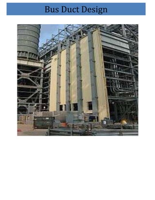
SlideShare a Scribd company logo
1 of 24
Bus Duct Design
BUS DUCTS
INTRODUCTION
Bus ducts or bus bars are used to carry very high current between
the generator and associated transformers, in the power stations. In
the power stations the generator voltages vary from 12 KV to 24
KV whereas auxiliary supply voltages are 3.3 KV, 6.6 KV, or 12
KV.

Bus bars are thick metal connectors, usually of aluminium, which
carry large current up to 10 KA for 200/250 MW sets and around
20 KA for 500 MW set. The conductors are metal enclosed,
usually aluminium to provide safety and reliable operation.

Considering the cost of copper and aluminium, the later has been
found to be an economical choice as conducting
Resistance-Temp coefficient per centigrade degree
                                0.00403                  0.00381

Density gm. per cc                   2.95                      8.9

Relative density                      1                        3.29

material for higher current bus ducts. Aluminium has been used for
the enclosure, as well as to reduce magnetic losses.

The enclosures and conductors are provided welded joints as for as
possible to give reduced maintenance. Bolted joints are provided
where opening is necessary during operation.

Aluminium is being used increasingly as busbar material, in power
stations, distribution boards, switchgear, etc. one of the main


                                                                     2
reasons for this is that it is cheaper to use than copper and making
allowance for the light metal’s.


TYPES OF BUSDUCTS
  1. Isolated phase busduct
  2. segregated busduct


ISOLATED PHASE BUSDUCT

INTRODUCTION:
Busduct forms the electrical link between generator , transformers
and associated equipments such as LAVT cubicle , UAT cubicle ,
NG cubicle etc. It is an assembly of busbars with associated joints
,connections and supporting insulators within a grounded metal
enclosure.

In Isolated Phase Bus duct each phase conductor is enclosed by an
individual metal housing and separated from adjacent phase
conductor housing by an air space. In the continuous I.P.Busduct
various sections are so interconnected that low resistance path for
the induced circulating current is provided from one phase
enclosure to other phase enclosure.


                                                                   3
DESIGN ASPECTS AND CRITERIA
The design of bus duct is governed by following Typical values
for parameters 3 X 210 MW Tenughat Proposal (ICB) is given
below:

  a) Rated Continuous Current for main bus       - 1000
     Amps
  b) Rated Continuous Current for Tap-off bus    -   1600 / 800
     Amps
  c) Rated Voltage                          - 15.75 KV
  d)
  e) Short time Current for main bus        -78 KA rms for 3Sec.
                                             225 KAP

  f) Short time Current for Tap-off bus     - 150 KA rms for 3
                                              sec/ 420 KAP

  g) Temperature rise allowed for bus enclosure    - 20 deg. C
                                                   Over 50 deg.C

  g) Temperature rise allowed for bus Conductor - 40 deg.(Plain
                                                    boltejoint)
                                                 Over 50deg.C

                                                  55 deg. C(Silver
                                                    plated joint)


The bus duct is designed to meet the above requirements and
following are the design out puts :


                                                                   4
I ) Bus bar :
                                    Main bus        Tap-off
a) Material and grade               Al. Alloy           Al.
Alloy
                                Grade 19501     Grade 63401

b) Shape                            Round              Square

c) Size    (Dia. & thickness)       450 O/D , 15 Tk.
                                              152.4A/F,8.1Tk.
                                         Box channel cond.


II ) Bus Enclosure :
a) Material and grade               Al. Alloy       Al. Alloy
                                    Grade 19500     Grade
31000

b) Shape                            Round            Round

c) Size    (Dia. & thickness)       1000 O/D,6.35 Tk.
                                           780 O/D4.78Tk.

III) Phase to Phase spacing              1250 mm         1000
mm


                                                                5
IV) Phase to earth clearance (min.)             220 mm         220
mm

V) Type of cooling                            Air Natraul

VI) Degree of Protection                Air and Water tightness
tests as per Appendix ‘F’
                                           of IS :8084


CONSTRUCTIONAL ASPECTS

The busduct enclosure is made of aluminium alloy sheet and
supplied in length upto 6-7 meters. It is further reinforced with
aluminium channel rings at intervals which are also used for
enclosure and insulator mounting . Sealed openings are provided in
the busduct run near insulator for inspection and maintenance.The
three phase enclosures are interconnected effectively at the ends to
permit flow of current. Different sections of each phase are
generally connected together by aluminium make up pieces at site.


ACCESSORIES :
RUBBER BELLOWS :

It is provided at Bus duct terminations and in the run of bus duct if
route length is more than 30 to 35 mtr. , to take care of machine
vibrations , alignment and expansion / contration due to
temperature variations. Further , it insulates the termination


                                                                     6
equipments connecting to bus duct and thus do not let the bus
enclosure currents to flow in the connecting equipments.


FLEXIBLES :

Copper flexibles are provided at bus duct terminations i.e at
Generator end , Generator transformer end , LAVT Cubicle , NG
Cubicle and other connecting equipment end. Aluminium flexibles
are provided in the run of bus duct to take care of alignment ,
variation in bus bar lengths due to temperature variations.


SEAL OFF BUSHINGS :

Epoxy Seal off bushings are provided at Power house wall and at
Generator termination end to restrict the propogation of fire in case
of accident. For air pressurised job’s , Seal off bushing is also
provided at Generator transformer end to form a close loop for
compressed air.


AIR PRESSURISATION EQUIPMENT. :

To avoid the ingress of dust , moistures etc. inside the bus duct , air
at a pressure slightly above the atmospheric pressure 25 to 40 mm
WC is flown in the busduct with the help of Air Pressurisation
Equipment.


                                                                      7
HOT AIR BLOWER :

After prolonged shutdown , to improve the IR value of Bus duct ,
Hot air is blown inside the bus duct with the help of Hot Air
Blower.


       Isolated Phase Bus-Duct


                                                               8
9
SEGREGATED PHASE BUSDUCT

INTRODUCTION:

Busduct forms the electrical link between generator , transformers
and associated equipments such as LAVT cubicle , UAT cubicle ,
NG cubicle etc. It is an assembly of busbars with associated joints
,connections and supporting insulators within a grounded metal
enclosure.

In Segregated Phase Bus duct all the three phase conductors are
housed in a metal enclosure with segregation between the phases
by means of a metallic / insulating barriers. This arrangement
reduces possibility of phase faults and also helps in reducing
temperature rise.


DESIGN ASPECTS AND CRITERIA


The design of bus duct is governed by following parameters .
Typical values for 250 MW Power Plant is given below:

  h) Rated Continuous Current for main bus         -   I) 2000
     Amps
                                             -    II) 2500 Amps
                                             -    III) 4000 Amps

  i) Rated Voltage                           -    6.6 KV


                                                                 10
j) Short time Current for           -        40 KA rms for 1
                                               Sec./102 KAP

  k) Temperature rise allowed for bus enclosure - 20 deg.C
                                                 Over 50 deg. C
  l) Temperature rise allowed for bus Conductor - 40 deg.C
                                                   Over 50 deg. C


The bus duct is designed to meet the above requirements and
following are the
 design out puts :


I ) Bus bar :
                                2000A / 2500 A          4000 A
a) Material and grade           Al. Alloy             Al Alloy
                                Grade 63401          Grade63401


b) Shape                              Square             Square

c) Size                              2X127 A/F,8.01 tk.
                                            2x177.8A/F,9.98 tk

                                 Box channel cond.        bcc


                                                                 11
II ) Bus Enclosure :
a) Material and grade                Al. Alloy        Al. Alloy
                                Grade 31000        Grade 31000

b) Shape                             Rectangular
                                                  Rectangular
c) Size                             450 X1350 ,3.15 tk.
                                            600 x1600 ,3.15 tk

III) Phase to Phase spacing           450 mm            540 mm

IV) Phase to earth clearance (min.) 90 mm               90mm

V) Type of cooling                        Air Natural

VI) Degree of Protection             Air and Water tightness
                                         Tests as per
                                     Appendix ‘F’ of IS : 8084


CONSTRUCTIONAL ASPECTS

The bus duct enclosure is made of aluminium alloy sheet and
supplied in length upto 3.72 meters. Insulating barriers of 2 mm
thick Aluminium sheet provide complete phase segregation inside
the enclosure. The Aluminium sheet is welded on a frame work
made up of Aluminium Angles.Bolted type inspection covers
provide access to the conductor joints and insulators. Neoprene
bonded cork gaskets are provided between the inspection covers


                                                                 12
and the enclosures in order to achieve fully weather proof duct and
air tight construction.The adjacent enclosures are connected
together by means of bolted type flange to flange joints.

Space heaters are provided to maintain IR value inside the bus
duct.


ACESSOCRIES

RUBBER BELLOWS :

 It is provided at Bus duct terminations and in the run of bus duct if
route length is more than 30 to 35 mtr. , to take care of machine
vibrations , alignment and expansion / contration due to
temperature variations. Further , it insulates the termination
equipments connecting to bus duct and thus do not let the bus
enclosure currents to flow in the connecting equipments.


FLEXIBLES :

Copper flexibles are provided at bus duct terminations. Aluminium
flexibles are provided in the run of bus duct to take care of
alignment , variation in bus bar lengths due to temperature
variations.


SEAL OFF BUSHINGS :

Epoxy Seal off bushings are provided at Power house wall to
restrict the propogation of fire in case of accident.


                                                                    13
Segregated Phase Bus-Duct


                            14
15
TYPES OF BUSBAR.
The three main types of busbar are as follows

                                            Flat shaped.
                                            Channel shaped.
                                            Tubular shaped.

The most commonly used busbars are rectangular in shape. Flat
conductors are easy to store, handle and erect. Whereas channel
busbars are however mechanically much stronger and electrically
more efficient because of larger effective cooling surfaces. This
construction also gives the structural advantage of a box girder
section, and can be used for unusually long spans or to withstand
high short circuit forces.


DESIGN CONSIDERATION
Busbar installation must be designed to operate within set
temperature limits and to withstand mechanical forces. A straight
substitution of aluminium for copper will not result in the most
economical use of material and designs for aluminium busbar
should be specially developed.


Very frequently the type, and sometimes the size, will be dictated
by the items served by the busbar; for example with switches and
circuit breakers, ease of connections will dictate the section
thickness and the space allowed may influence the choice of
conductor shape. In other cases, the designer may have a free hand,
unhampered by existing designs.


                                                                 16
TEMPERATURE RISE
In the majority of busbar installations the rating is established on
the basis of temperature rise. Connections are usually short and
power losses and voltage drop are not significant.

The operating temperature of a busbar must be limited to a level at
which there will be no long term deterioration of the conductor, the
joints or the equipment connected to the busbar. In normal practice
the temperature rise must not exceed 50◦ c on an ambient having a
peak value of 40◦ c and an average value of 35◦ c, giving a
maximum operating temperature of 85◦ c.

This allows an adequate margin of mechanical strength and can be
operated on a continuous basis at temperature of upto 110◦ c
without loss of strength.

Particular attention is given to factors such as joint design and
thermal expansion. The temperature of busbar will rise until the
heat dissipated is equal to the heat generated. This has direct
bearing on current carrying capacity of the conductor, by virtue of
the effect of temperature on resistance.


VOLTAGE-DROP&TEMPERATURE
RISE
The voltage-drop on a busbar can often be ignored, but cases occur
in both D.c and A.c systems where it is the criterion in the design.

In a D.c system, the voltage-drop is due solely to resistance. And
this can be reduced only by the use of larger total cross-section,

                                                                  17
either by increasing the number of conductors or by using larger
ones.

In A.c systems, voltage-drop is due mainly to reactance which can
be minimized by making the busbar spacing small

For the same energy loss an aluminium bar will carry 78.2% of the
full load current of a copper bar of the same physical dimensions.


POWER LOSS
Although a busbar is at times defined as a conductor having
negligible loss, there are many cases, particularly where the load
factor is high, where losses are very important. If the busbar is
designed to have the full permissible temperature rise, the loses
may be too great, and it may be more economical to spend more
money on the busbar to get higher efficiency.

The money value of the losses must take into account not only the
cost of units consumed over the years, but also the maximum
demand charge for the KW loss at full-load.


CLEARANCES
The recommended clearances are given between busbar and busbar
connections.


                                                                18
FORCES ACTING ON BUSBARS

WEIGHT

The lightness of aluminium bus bar is of great assistance in
erection. It also confers a substantial advantage in the design of
rising main busbar where each busbar must be supported at its
upper end by a suspension insulator.

WIND AND ICE

In the case of outdoor busbar, the forces to be considered include
wind and ice. Allowances must be made for ice forming to a radial
thickness of 9.5 mm. The weight of ice is 913 Kg./cu. m. The wind
loading is to be taken as 39 Kg/sq m. on the ice covered conductor.

EXPANSION FORCES

Busbars changes temperature with load much more rapidly than its
support and hence relative movement between the two must occur.
If a bar is anchored in one place only, and allowed to slide
elsewhere, this expansion can probably be absorbed at corners in
the run. A further reason for employing expansion joints is to
ensure that deflections due to short-circuit forces do not cause
longitudinal forces that can be stress the material and damage the
insulators.

ELECTRO-MAGNETIC FORCES

In many cases, the electro-magnetic forces will be appreciably
larger than all others, running perhaps to a thousand Kgms per
meter run, or even more under the most severe short-circuit
conditions.


                                                                 19
The mechanical forces and the temperature rise due to the very
high currents are often the limiting factors in the busbar design.


BUSDUCTS WELDING

Base Metal Preparation

Prior to weld Al, the base metal, must be cleaned to remove any
aluminium oxide and hydrocarbon contamination from oils or
cutting solvents.


Requirements of Aluminium Welding

Since the melting point of oxide (approx. 3700F) is greater than the
base metal (approx.1200F), therefore leaving any oxide on the
surface of the base metal will inhibit penetration of the filler metal
into the metal work piece. To remove the oxide use of stainless
steel brush or solvent or etching solution could be made..

Preheating

It helps avoid weld cracking. Placing tack welds in the beginning
and end of the area to be welded will aid in the preheating effort.

Travel Speed
Aluminium welding needs to be performed hot and fast. If speed is
to low the welder risks excessive bum through particularly on thin
gauge sheet.


                                                                    20
Filler Wire

Filler wire must be selected so that it has a melting temperature
similar to the base metal. The larger the wire diameter the easier it
feeds. Filler with high alloy content than the base should be easier
as filler remains plastic after the base hardens, relieving stresses by
yielding until solidification.

The Push Technique

With aluminium pushing the gun away from the weld puddle rather
than pulling it will result in better cleaning action, reduced weld
contamination, and improved shielding gas coverage.


Shielding Gas

It should have good cleaning action and penetration profile. Argon
is the most common shielding gas preferred in view of economy.
When welding aluminium argon gas of 99.997% purity is required
for radiographic welding.

Convex Shaped Weld

Till aluminium welding crater cracking causes most failures the
risk of cracking is greatest with concave craters, since the surface
of craters contracts and tears as it cools. Therefore craters should
be built up to convex or mould shape. As the weld cools, convex
shape of crater compensates for contraction forces.


Installation-photo-:

                                                                     21
22
BUSBARS PROTECTION

Busbars are vital parts of a power system and so a fault should be
cleared as fast as possible. A busbar must have its own protection
although their high degrees of reliability bearing in mind the risk
of unnecessary trips, so the protection should be dependable,
selective and should be stable for external faults, called through
faults.

The most common fault is phase to ground, which usually results
from human error.

There are many types of relaying principles used in busbar. A
special attention should be made to current transformer selection
since measuring errors need to be considered.

The proposed protection employs a protection technique based on
polarities of transient current waves for identification of the faults
internal and external to the busbar. In the technique, the polarities
of transient currents can be extracted reliably using a wavelet
transform modulus maximum. To improve the reliability of the
distributed busbar protection system, message exchange based on
"protection signal bus" is presented and applied for the
implementation of distributed bus protection. Using this method
the comparison and exchange of polarity information among the
protection units can be completed reliably.                          .


                                                                    23
24

More Related Content

What's hot

Electric substation
Electric substation Electric substation
Electric substation ANNU KUMAR
 
Substation Training presentation
Substation Training presentationSubstation Training presentation
Substation Training presentationKamal Mittal
 
Operation and maintenance of transformer
Operation and maintenance of transformerOperation and maintenance of transformer
Operation and maintenance of transformerKapil Singh
 
PPt on 220 kV substation
PPt on 220 kV substationPPt on 220 kV substation
PPt on 220 kV substationIshank Ranjan
 
220 KV Substation Operation & Maintenance
220 KV Substation Operation & Maintenance220 KV Substation Operation & Maintenance
220 KV Substation Operation & MaintenanceHimansu Pradhan
 
400kv sub-station-final-ppt-by-mohit
400kv sub-station-final-ppt-by-mohit400kv sub-station-final-ppt-by-mohit
400kv sub-station-final-ppt-by-mohitMohit Awasthi
 
GIS (Gas-Insulated Substation) by Bharat & Shanni
GIS (Gas-Insulated Substation) by Bharat & ShanniGIS (Gas-Insulated Substation) by Bharat & Shanni
GIS (Gas-Insulated Substation) by Bharat & ShanniBHARATKUMAR RATHOD
 
Protection & switchgear
Protection & switchgear   Protection & switchgear
Protection & switchgear johny renoald
 
POWER SYSTEM PROTECTION
POWER SYSTEM PROTECTION POWER SYSTEM PROTECTION
POWER SYSTEM PROTECTION moiz89
 
Transformer protection
Transformer protectionTransformer protection
Transformer protectionjawaharramaya
 
presentation on substation layout and BUS bar arrangement.
presentation on substation layout and BUS bar arrangement.presentation on substation layout and BUS bar arrangement.
presentation on substation layout and BUS bar arrangement.Hemendra Kumar Rajput
 
Power system stability
Power system stabilityPower system stability
Power system stabilityBalaram Das
 
Substation and It's Equipment
Substation and It's Equipment Substation and It's Equipment
Substation and It's Equipment Chandan Kumar
 
Stability test of transformer
Stability test of transformerStability test of transformer
Stability test of transformerSantu Mondal
 
Load Distribution
Load DistributionLoad Distribution
Load DistributionArpit Gupta
 
Presentation on substations
Presentation on substationsPresentation on substations
Presentation on substationsvishalgohel12195
 

What's hot (20)

Protection and Switchgear
Protection and SwitchgearProtection and Switchgear
Protection and Switchgear
 
Electric substation
Electric substation Electric substation
Electric substation
 
Substation Training presentation
Substation Training presentationSubstation Training presentation
Substation Training presentation
 
Operation and maintenance of transformer
Operation and maintenance of transformerOperation and maintenance of transformer
Operation and maintenance of transformer
 
PPt on 220 kV substation
PPt on 220 kV substationPPt on 220 kV substation
PPt on 220 kV substation
 
220 KV Substation Operation & Maintenance
220 KV Substation Operation & Maintenance220 KV Substation Operation & Maintenance
220 KV Substation Operation & Maintenance
 
400kv sub-station-final-ppt-by-mohit
400kv sub-station-final-ppt-by-mohit400kv sub-station-final-ppt-by-mohit
400kv sub-station-final-ppt-by-mohit
 
GIS (Gas-Insulated Substation) by Bharat & Shanni
GIS (Gas-Insulated Substation) by Bharat & ShanniGIS (Gas-Insulated Substation) by Bharat & Shanni
GIS (Gas-Insulated Substation) by Bharat & Shanni
 
Ehv substation
Ehv substationEhv substation
Ehv substation
 
Protection & switchgear
Protection & switchgear   Protection & switchgear
Protection & switchgear
 
POWER SYSTEM PROTECTION
POWER SYSTEM PROTECTION POWER SYSTEM PROTECTION
POWER SYSTEM PROTECTION
 
Transformer protection
Transformer protectionTransformer protection
Transformer protection
 
presentation on substation layout and BUS bar arrangement.
presentation on substation layout and BUS bar arrangement.presentation on substation layout and BUS bar arrangement.
presentation on substation layout and BUS bar arrangement.
 
Power system stability
Power system stabilityPower system stability
Power system stability
 
Introduction to mv switchgear
Introduction to mv switchgearIntroduction to mv switchgear
Introduction to mv switchgear
 
Substation and It's Equipment
Substation and It's Equipment Substation and It's Equipment
Substation and It's Equipment
 
Stability test of transformer
Stability test of transformerStability test of transformer
Stability test of transformer
 
Load Distribution
Load DistributionLoad Distribution
Load Distribution
 
Presentation on substations
Presentation on substationsPresentation on substations
Presentation on substations
 
Substations
Substations Substations
Substations
 

Similar to Bus duct fabrication

Metal enclosed busduct
Metal enclosed busductMetal enclosed busduct
Metal enclosed busductAmit Agrawal
 
Case study sterlite deadend grip
Case study  sterlite deadend gripCase study  sterlite deadend grip
Case study sterlite deadend gripHarish Agarwal
 
Ls busduct -tnhh kimxuan
Ls busduct -tnhh kimxuanLs busduct -tnhh kimxuan
Ls busduct -tnhh kimxuanNgan TNHH
 
New generation of copper conductors for overhead lines
New generation of copper conductors for overhead linesNew generation of copper conductors for overhead lines
New generation of copper conductors for overhead linesLeonardo ENERGY
 
New generation of copper conductors for overhead lines
New generation of copper conductors for overhead linesNew generation of copper conductors for overhead lines
New generation of copper conductors for overhead linesLeonardo ENERGY
 
Single phase induction motor Design.pptx
Single phase induction motor Design.pptxSingle phase induction motor Design.pptx
Single phase induction motor Design.pptxFaisalSheraz4
 
KB Electric may bien ap kho Ls nhap khau Korea
KB Electric may bien ap kho Ls nhap khau KoreaKB Electric may bien ap kho Ls nhap khau Korea
KB Electric may bien ap kho Ls nhap khau KoreaKB ELECTRIC
 
50 armando rodriguez valadez - 6204452 - flexible automotive electrical con...
50   armando rodriguez valadez - 6204452 - flexible automotive electrical con...50   armando rodriguez valadez - 6204452 - flexible automotive electrical con...
50 armando rodriguez valadez - 6204452 - flexible automotive electrical con...Mello_Patent_Registry
 
160511 160804-electrical machine design
160511 160804-electrical machine design160511 160804-electrical machine design
160511 160804-electrical machine designPalak Ariwala
 
Rail, sleepers fittings.ppt
Rail, sleepers  fittings.pptRail, sleepers  fittings.ppt
Rail, sleepers fittings.pptAdityaDubewar2
 
ECNG 3015 chapter 6 - switchgear technology
ECNG 3015  chapter 6 - switchgear technologyECNG 3015  chapter 6 - switchgear technology
ECNG 3015 chapter 6 - switchgear technologyChandrabhan Sharma
 
CABLE DISTRIBUTION PANEL EMERSON EDUARDO RODRIGUES
CABLE DISTRIBUTION PANEL EMERSON EDUARDO RODRIGUESCABLE DISTRIBUTION PANEL EMERSON EDUARDO RODRIGUES
CABLE DISTRIBUTION PANEL EMERSON EDUARDO RODRIGUESEMERSON EDUARDO RODRIGUES
 
CABLE DISTRIBUTION PANEL EMERSON EDUARDO RODRIGUES
CABLE DISTRIBUTION PANEL EMERSON EDUARDO RODRIGUESCABLE DISTRIBUTION PANEL EMERSON EDUARDO RODRIGUES
CABLE DISTRIBUTION PANEL EMERSON EDUARDO RODRIGUESEMERSON EDUARDO RODRIGUES
 
Transpower Switchgear Industries, Mumbai, Electrical Products
Transpower Switchgear Industries, Mumbai, Electrical ProductsTranspower Switchgear Industries, Mumbai, Electrical Products
Transpower Switchgear Industries, Mumbai, Electrical ProductsIndiaMART InterMESH Limited
 
transmission line
transmission line transmission line
transmission line singh1515
 
Steel stacks guide
Steel stacks guideSteel stacks guide
Steel stacks guideKhaled Eid
 
Nexans Euromold K400TB 630A 24kV Bolted Tee Connectors 35-300sqmm - Nexans Eu...
Nexans Euromold K400TB 630A 24kV Bolted Tee Connectors 35-300sqmm - Nexans Eu...Nexans Euromold K400TB 630A 24kV Bolted Tee Connectors 35-300sqmm - Nexans Eu...
Nexans Euromold K400TB 630A 24kV Bolted Tee Connectors 35-300sqmm - Nexans Eu...Thorne & Derrick International
 
Nexans Euromold M400TB 630A 33kV Bolted Tee Connectors 35-185sqmm - Nexans Eu...
Nexans Euromold M400TB 630A 33kV Bolted Tee Connectors 35-185sqmm - Nexans Eu...Nexans Euromold M400TB 630A 33kV Bolted Tee Connectors 35-185sqmm - Nexans Eu...
Nexans Euromold M400TB 630A 33kV Bolted Tee Connectors 35-185sqmm - Nexans Eu...Thorne & Derrick International
 

Similar to Bus duct fabrication (20)

Metal enclosed busduct
Metal enclosed busductMetal enclosed busduct
Metal enclosed busduct
 
Case study sterlite deadend grip
Case study  sterlite deadend gripCase study  sterlite deadend grip
Case study sterlite deadend grip
 
Ls busduct -tnhh kimxuan
Ls busduct -tnhh kimxuanLs busduct -tnhh kimxuan
Ls busduct -tnhh kimxuan
 
New generation of copper conductors for overhead lines
New generation of copper conductors for overhead linesNew generation of copper conductors for overhead lines
New generation of copper conductors for overhead lines
 
New generation of copper conductors for overhead lines
New generation of copper conductors for overhead linesNew generation of copper conductors for overhead lines
New generation of copper conductors for overhead lines
 
unit-iv.pptx
unit-iv.pptxunit-iv.pptx
unit-iv.pptx
 
Single phase induction motor Design.pptx
Single phase induction motor Design.pptxSingle phase induction motor Design.pptx
Single phase induction motor Design.pptx
 
KB Electric may bien ap kho Ls nhap khau Korea
KB Electric may bien ap kho Ls nhap khau KoreaKB Electric may bien ap kho Ls nhap khau Korea
KB Electric may bien ap kho Ls nhap khau Korea
 
50 armando rodriguez valadez - 6204452 - flexible automotive electrical con...
50   armando rodriguez valadez - 6204452 - flexible automotive electrical con...50   armando rodriguez valadez - 6204452 - flexible automotive electrical con...
50 armando rodriguez valadez - 6204452 - flexible automotive electrical con...
 
160511 160804-electrical machine design
160511 160804-electrical machine design160511 160804-electrical machine design
160511 160804-electrical machine design
 
Rail, sleepers fittings.ppt
Rail, sleepers  fittings.pptRail, sleepers  fittings.ppt
Rail, sleepers fittings.ppt
 
ECNG 3015 chapter 6 - switchgear technology
ECNG 3015  chapter 6 - switchgear technologyECNG 3015  chapter 6 - switchgear technology
ECNG 3015 chapter 6 - switchgear technology
 
Specifications
SpecificationsSpecifications
Specifications
 
CABLE DISTRIBUTION PANEL EMERSON EDUARDO RODRIGUES
CABLE DISTRIBUTION PANEL EMERSON EDUARDO RODRIGUESCABLE DISTRIBUTION PANEL EMERSON EDUARDO RODRIGUES
CABLE DISTRIBUTION PANEL EMERSON EDUARDO RODRIGUES
 
CABLE DISTRIBUTION PANEL EMERSON EDUARDO RODRIGUES
CABLE DISTRIBUTION PANEL EMERSON EDUARDO RODRIGUESCABLE DISTRIBUTION PANEL EMERSON EDUARDO RODRIGUES
CABLE DISTRIBUTION PANEL EMERSON EDUARDO RODRIGUES
 
Transpower Switchgear Industries, Mumbai, Electrical Products
Transpower Switchgear Industries, Mumbai, Electrical ProductsTranspower Switchgear Industries, Mumbai, Electrical Products
Transpower Switchgear Industries, Mumbai, Electrical Products
 
transmission line
transmission line transmission line
transmission line
 
Steel stacks guide
Steel stacks guideSteel stacks guide
Steel stacks guide
 
Nexans Euromold K400TB 630A 24kV Bolted Tee Connectors 35-300sqmm - Nexans Eu...
Nexans Euromold K400TB 630A 24kV Bolted Tee Connectors 35-300sqmm - Nexans Eu...Nexans Euromold K400TB 630A 24kV Bolted Tee Connectors 35-300sqmm - Nexans Eu...
Nexans Euromold K400TB 630A 24kV Bolted Tee Connectors 35-300sqmm - Nexans Eu...
 
Nexans Euromold M400TB 630A 33kV Bolted Tee Connectors 35-185sqmm - Nexans Eu...
Nexans Euromold M400TB 630A 33kV Bolted Tee Connectors 35-185sqmm - Nexans Eu...Nexans Euromold M400TB 630A 33kV Bolted Tee Connectors 35-185sqmm - Nexans Eu...
Nexans Euromold M400TB 630A 33kV Bolted Tee Connectors 35-185sqmm - Nexans Eu...
 

Bus duct fabrication

  • 2. BUS DUCTS INTRODUCTION Bus ducts or bus bars are used to carry very high current between the generator and associated transformers, in the power stations. In the power stations the generator voltages vary from 12 KV to 24 KV whereas auxiliary supply voltages are 3.3 KV, 6.6 KV, or 12 KV. Bus bars are thick metal connectors, usually of aluminium, which carry large current up to 10 KA for 200/250 MW sets and around 20 KA for 500 MW set. The conductors are metal enclosed, usually aluminium to provide safety and reliable operation. Considering the cost of copper and aluminium, the later has been found to be an economical choice as conducting Resistance-Temp coefficient per centigrade degree 0.00403 0.00381 Density gm. per cc 2.95 8.9 Relative density 1 3.29 material for higher current bus ducts. Aluminium has been used for the enclosure, as well as to reduce magnetic losses. The enclosures and conductors are provided welded joints as for as possible to give reduced maintenance. Bolted joints are provided where opening is necessary during operation. Aluminium is being used increasingly as busbar material, in power stations, distribution boards, switchgear, etc. one of the main 2
  • 3. reasons for this is that it is cheaper to use than copper and making allowance for the light metal’s. TYPES OF BUSDUCTS 1. Isolated phase busduct 2. segregated busduct ISOLATED PHASE BUSDUCT INTRODUCTION: Busduct forms the electrical link between generator , transformers and associated equipments such as LAVT cubicle , UAT cubicle , NG cubicle etc. It is an assembly of busbars with associated joints ,connections and supporting insulators within a grounded metal enclosure. In Isolated Phase Bus duct each phase conductor is enclosed by an individual metal housing and separated from adjacent phase conductor housing by an air space. In the continuous I.P.Busduct various sections are so interconnected that low resistance path for the induced circulating current is provided from one phase enclosure to other phase enclosure. 3
  • 4. DESIGN ASPECTS AND CRITERIA The design of bus duct is governed by following Typical values for parameters 3 X 210 MW Tenughat Proposal (ICB) is given below: a) Rated Continuous Current for main bus - 1000 Amps b) Rated Continuous Current for Tap-off bus - 1600 / 800 Amps c) Rated Voltage - 15.75 KV d) e) Short time Current for main bus -78 KA rms for 3Sec. 225 KAP f) Short time Current for Tap-off bus - 150 KA rms for 3 sec/ 420 KAP g) Temperature rise allowed for bus enclosure - 20 deg. C Over 50 deg.C g) Temperature rise allowed for bus Conductor - 40 deg.(Plain boltejoint) Over 50deg.C 55 deg. C(Silver plated joint) The bus duct is designed to meet the above requirements and following are the design out puts : 4
  • 5. I ) Bus bar : Main bus Tap-off a) Material and grade Al. Alloy Al. Alloy Grade 19501 Grade 63401 b) Shape Round Square c) Size (Dia. & thickness) 450 O/D , 15 Tk. 152.4A/F,8.1Tk. Box channel cond. II ) Bus Enclosure : a) Material and grade Al. Alloy Al. Alloy Grade 19500 Grade 31000 b) Shape Round Round c) Size (Dia. & thickness) 1000 O/D,6.35 Tk. 780 O/D4.78Tk. III) Phase to Phase spacing 1250 mm 1000 mm 5
  • 6. IV) Phase to earth clearance (min.) 220 mm 220 mm V) Type of cooling Air Natraul VI) Degree of Protection Air and Water tightness tests as per Appendix ‘F’ of IS :8084 CONSTRUCTIONAL ASPECTS The busduct enclosure is made of aluminium alloy sheet and supplied in length upto 6-7 meters. It is further reinforced with aluminium channel rings at intervals which are also used for enclosure and insulator mounting . Sealed openings are provided in the busduct run near insulator for inspection and maintenance.The three phase enclosures are interconnected effectively at the ends to permit flow of current. Different sections of each phase are generally connected together by aluminium make up pieces at site. ACCESSORIES : RUBBER BELLOWS : It is provided at Bus duct terminations and in the run of bus duct if route length is more than 30 to 35 mtr. , to take care of machine vibrations , alignment and expansion / contration due to temperature variations. Further , it insulates the termination 6
  • 7. equipments connecting to bus duct and thus do not let the bus enclosure currents to flow in the connecting equipments. FLEXIBLES : Copper flexibles are provided at bus duct terminations i.e at Generator end , Generator transformer end , LAVT Cubicle , NG Cubicle and other connecting equipment end. Aluminium flexibles are provided in the run of bus duct to take care of alignment , variation in bus bar lengths due to temperature variations. SEAL OFF BUSHINGS : Epoxy Seal off bushings are provided at Power house wall and at Generator termination end to restrict the propogation of fire in case of accident. For air pressurised job’s , Seal off bushing is also provided at Generator transformer end to form a close loop for compressed air. AIR PRESSURISATION EQUIPMENT. : To avoid the ingress of dust , moistures etc. inside the bus duct , air at a pressure slightly above the atmospheric pressure 25 to 40 mm WC is flown in the busduct with the help of Air Pressurisation Equipment. 7
  • 8. HOT AIR BLOWER : After prolonged shutdown , to improve the IR value of Bus duct , Hot air is blown inside the bus duct with the help of Hot Air Blower. Isolated Phase Bus-Duct 8
  • 9. 9
  • 10. SEGREGATED PHASE BUSDUCT INTRODUCTION: Busduct forms the electrical link between generator , transformers and associated equipments such as LAVT cubicle , UAT cubicle , NG cubicle etc. It is an assembly of busbars with associated joints ,connections and supporting insulators within a grounded metal enclosure. In Segregated Phase Bus duct all the three phase conductors are housed in a metal enclosure with segregation between the phases by means of a metallic / insulating barriers. This arrangement reduces possibility of phase faults and also helps in reducing temperature rise. DESIGN ASPECTS AND CRITERIA The design of bus duct is governed by following parameters . Typical values for 250 MW Power Plant is given below: h) Rated Continuous Current for main bus - I) 2000 Amps - II) 2500 Amps - III) 4000 Amps i) Rated Voltage - 6.6 KV 10
  • 11. j) Short time Current for - 40 KA rms for 1 Sec./102 KAP k) Temperature rise allowed for bus enclosure - 20 deg.C Over 50 deg. C l) Temperature rise allowed for bus Conductor - 40 deg.C Over 50 deg. C The bus duct is designed to meet the above requirements and following are the design out puts : I ) Bus bar : 2000A / 2500 A 4000 A a) Material and grade Al. Alloy Al Alloy Grade 63401 Grade63401 b) Shape Square Square c) Size 2X127 A/F,8.01 tk. 2x177.8A/F,9.98 tk Box channel cond. bcc 11
  • 12. II ) Bus Enclosure : a) Material and grade Al. Alloy Al. Alloy Grade 31000 Grade 31000 b) Shape Rectangular Rectangular c) Size 450 X1350 ,3.15 tk. 600 x1600 ,3.15 tk III) Phase to Phase spacing 450 mm 540 mm IV) Phase to earth clearance (min.) 90 mm 90mm V) Type of cooling Air Natural VI) Degree of Protection Air and Water tightness Tests as per Appendix ‘F’ of IS : 8084 CONSTRUCTIONAL ASPECTS The bus duct enclosure is made of aluminium alloy sheet and supplied in length upto 3.72 meters. Insulating barriers of 2 mm thick Aluminium sheet provide complete phase segregation inside the enclosure. The Aluminium sheet is welded on a frame work made up of Aluminium Angles.Bolted type inspection covers provide access to the conductor joints and insulators. Neoprene bonded cork gaskets are provided between the inspection covers 12
  • 13. and the enclosures in order to achieve fully weather proof duct and air tight construction.The adjacent enclosures are connected together by means of bolted type flange to flange joints. Space heaters are provided to maintain IR value inside the bus duct. ACESSOCRIES RUBBER BELLOWS : It is provided at Bus duct terminations and in the run of bus duct if route length is more than 30 to 35 mtr. , to take care of machine vibrations , alignment and expansion / contration due to temperature variations. Further , it insulates the termination equipments connecting to bus duct and thus do not let the bus enclosure currents to flow in the connecting equipments. FLEXIBLES : Copper flexibles are provided at bus duct terminations. Aluminium flexibles are provided in the run of bus duct to take care of alignment , variation in bus bar lengths due to temperature variations. SEAL OFF BUSHINGS : Epoxy Seal off bushings are provided at Power house wall to restrict the propogation of fire in case of accident. 13
  • 15. 15
  • 16. TYPES OF BUSBAR. The three main types of busbar are as follows Flat shaped. Channel shaped. Tubular shaped. The most commonly used busbars are rectangular in shape. Flat conductors are easy to store, handle and erect. Whereas channel busbars are however mechanically much stronger and electrically more efficient because of larger effective cooling surfaces. This construction also gives the structural advantage of a box girder section, and can be used for unusually long spans or to withstand high short circuit forces. DESIGN CONSIDERATION Busbar installation must be designed to operate within set temperature limits and to withstand mechanical forces. A straight substitution of aluminium for copper will not result in the most economical use of material and designs for aluminium busbar should be specially developed. Very frequently the type, and sometimes the size, will be dictated by the items served by the busbar; for example with switches and circuit breakers, ease of connections will dictate the section thickness and the space allowed may influence the choice of conductor shape. In other cases, the designer may have a free hand, unhampered by existing designs. 16
  • 17. TEMPERATURE RISE In the majority of busbar installations the rating is established on the basis of temperature rise. Connections are usually short and power losses and voltage drop are not significant. The operating temperature of a busbar must be limited to a level at which there will be no long term deterioration of the conductor, the joints or the equipment connected to the busbar. In normal practice the temperature rise must not exceed 50◦ c on an ambient having a peak value of 40◦ c and an average value of 35◦ c, giving a maximum operating temperature of 85◦ c. This allows an adequate margin of mechanical strength and can be operated on a continuous basis at temperature of upto 110◦ c without loss of strength. Particular attention is given to factors such as joint design and thermal expansion. The temperature of busbar will rise until the heat dissipated is equal to the heat generated. This has direct bearing on current carrying capacity of the conductor, by virtue of the effect of temperature on resistance. VOLTAGE-DROP&TEMPERATURE RISE The voltage-drop on a busbar can often be ignored, but cases occur in both D.c and A.c systems where it is the criterion in the design. In a D.c system, the voltage-drop is due solely to resistance. And this can be reduced only by the use of larger total cross-section, 17
  • 18. either by increasing the number of conductors or by using larger ones. In A.c systems, voltage-drop is due mainly to reactance which can be minimized by making the busbar spacing small For the same energy loss an aluminium bar will carry 78.2% of the full load current of a copper bar of the same physical dimensions. POWER LOSS Although a busbar is at times defined as a conductor having negligible loss, there are many cases, particularly where the load factor is high, where losses are very important. If the busbar is designed to have the full permissible temperature rise, the loses may be too great, and it may be more economical to spend more money on the busbar to get higher efficiency. The money value of the losses must take into account not only the cost of units consumed over the years, but also the maximum demand charge for the KW loss at full-load. CLEARANCES The recommended clearances are given between busbar and busbar connections. 18
  • 19. FORCES ACTING ON BUSBARS WEIGHT The lightness of aluminium bus bar is of great assistance in erection. It also confers a substantial advantage in the design of rising main busbar where each busbar must be supported at its upper end by a suspension insulator. WIND AND ICE In the case of outdoor busbar, the forces to be considered include wind and ice. Allowances must be made for ice forming to a radial thickness of 9.5 mm. The weight of ice is 913 Kg./cu. m. The wind loading is to be taken as 39 Kg/sq m. on the ice covered conductor. EXPANSION FORCES Busbars changes temperature with load much more rapidly than its support and hence relative movement between the two must occur. If a bar is anchored in one place only, and allowed to slide elsewhere, this expansion can probably be absorbed at corners in the run. A further reason for employing expansion joints is to ensure that deflections due to short-circuit forces do not cause longitudinal forces that can be stress the material and damage the insulators. ELECTRO-MAGNETIC FORCES In many cases, the electro-magnetic forces will be appreciably larger than all others, running perhaps to a thousand Kgms per meter run, or even more under the most severe short-circuit conditions. 19
  • 20. The mechanical forces and the temperature rise due to the very high currents are often the limiting factors in the busbar design. BUSDUCTS WELDING Base Metal Preparation Prior to weld Al, the base metal, must be cleaned to remove any aluminium oxide and hydrocarbon contamination from oils or cutting solvents. Requirements of Aluminium Welding Since the melting point of oxide (approx. 3700F) is greater than the base metal (approx.1200F), therefore leaving any oxide on the surface of the base metal will inhibit penetration of the filler metal into the metal work piece. To remove the oxide use of stainless steel brush or solvent or etching solution could be made.. Preheating It helps avoid weld cracking. Placing tack welds in the beginning and end of the area to be welded will aid in the preheating effort. Travel Speed Aluminium welding needs to be performed hot and fast. If speed is to low the welder risks excessive bum through particularly on thin gauge sheet. 20
  • 21. Filler Wire Filler wire must be selected so that it has a melting temperature similar to the base metal. The larger the wire diameter the easier it feeds. Filler with high alloy content than the base should be easier as filler remains plastic after the base hardens, relieving stresses by yielding until solidification. The Push Technique With aluminium pushing the gun away from the weld puddle rather than pulling it will result in better cleaning action, reduced weld contamination, and improved shielding gas coverage. Shielding Gas It should have good cleaning action and penetration profile. Argon is the most common shielding gas preferred in view of economy. When welding aluminium argon gas of 99.997% purity is required for radiographic welding. Convex Shaped Weld Till aluminium welding crater cracking causes most failures the risk of cracking is greatest with concave craters, since the surface of craters contracts and tears as it cools. Therefore craters should be built up to convex or mould shape. As the weld cools, convex shape of crater compensates for contraction forces. Installation-photo-: 21
  • 22. 22
  • 23. BUSBARS PROTECTION Busbars are vital parts of a power system and so a fault should be cleared as fast as possible. A busbar must have its own protection although their high degrees of reliability bearing in mind the risk of unnecessary trips, so the protection should be dependable, selective and should be stable for external faults, called through faults. The most common fault is phase to ground, which usually results from human error. There are many types of relaying principles used in busbar. A special attention should be made to current transformer selection since measuring errors need to be considered. The proposed protection employs a protection technique based on polarities of transient current waves for identification of the faults internal and external to the busbar. In the technique, the polarities of transient currents can be extracted reliably using a wavelet transform modulus maximum. To improve the reliability of the distributed busbar protection system, message exchange based on "protection signal bus" is presented and applied for the implementation of distributed bus protection. Using this method the comparison and exchange of polarity information among the protection units can be completed reliably. . 23
  • 24. 24