SlideShare una empresa de Scribd logo
1 de 141
Descargar para leer sin conexión
 
  
Hardware Reference Manual for i.MX53 Quick Start-R                                IMX53QSBRM‐R 


     i.MX53 Quick Start-R Board
     Take your Multimedia                                                   freescale          TM 


     Experience to the max                                                      semiconductor


 Freescale Semiconductor
 Hardware User Guide for i.MX53 Quick Start-R Board,        Preliminary Rev 0.5            i
                            PUBI – Public Use Business Information  


How to Reach Us:                             
Home Page:
www.freescale.com

E-mail:
support@freescale.com

USA/Europe or Locations Not Listed:
Freescale Semiconductor
Technical Information Center, CH370
1300 N. Alma School Road
Chandler, Arizona 85224
+1-800-521-6274 or +1-480-768-2130
support@freescale.com
                                                         Information in this document is provided solely to enable system and software
Europe, Middle East, and Africa:                         implementers to use Freescale Semiconductor products. There are no express or
Freescale Halbleiter Deutschland GmbH                    implied copyright licenses granted hereunder to design or fabricate any integrated
Technical Information Center                             circuits or integrated circuits based on the information in this document.
Schatzbogen 7                                            Freescale Semiconductor reserves the right to make changes without further notice
81829 Muenchen, Germany                                  to any products herein. Freescale Semiconductor makes no warranty, representation
+44 1296 380 456 (English)                               or guarantee regarding the suitability of its products for any particular purpose, nor
+46 8 52200080 (English)                                 does Freescale Semiconductor assume any liability arising out of the application or
+49 89 92103 559 (German)                                use of any product or circuit, and specifically disclaims any and all liability, including
+33 1 69 35 48 48 (French)                               without limitation consequential or incidental damages. “Typical” parameters that may
support@freescale.com                                    be provided in Freescale Semiconductor data sheets and/or specifications can and
                                                         do vary in different applications and actual performance may vary over time. All
Japan:                                                   operating parameters, including “Typicals”, must be validated for each customer
Freescale Semiconductor Japan Ltd.                       application by customer’s technical experts. Freescale Semiconductor does not
Headquarters                                             convey any license under its patent rights nor the rights of others. Freescale
ARCO Tower 15F                                           Semiconductor products are not designed, intended, or authorized for use as
1-8-1, Shimo-Meguro, Meguro-ku,                          components in systems intended for surgical implant into the body, or other
Tokyo 153-0064, Japan                                    applications intended to support or sustain life, or for any other application in which
0120 191014 or +81 3 5437 9125                           the failure of the Freescale Semiconductor product could create a situation where
support.japan@freescale.com                              personal injury or death may occur. Should Buyer purchase or use Freescale
                                                         Semiconductor products for any such unintended or unauthorized application, Buyer
Asia/Pacific:                                            shall indemnify and hold Freescale Semiconductor and its officers, employees,
Freescale Semiconductor Hong Kong Ltd.                   subsidiaries, affiliates, and distributors harmless against all claims, costs, damages,
Technical Information Center                             and expenses, and reasonable attorney fees arising out of, directly or indirectly, any
2 Dai King Street                                        claim of personal injury or death associated with such unintended or unauthorized
Tai Po Industrial Estate                                 use, even if such claim alleges that Freescale Semiconductor was negligent
Tai Po, N.T., Hong Kong                                  regarding the design or manufacture of the part.
+800 2666 8080
support.asia@freescale.com                               Learn More: For more information about Freescale products, please visit
                                                         www.freescale.com.
For Literature Requests Only:
Freescale Semiconductor Literature Distribution Center   Freescale™ and the Freescale logo are trademarks of Freescale Semiconductor, Inc.
P.O. Box 5405                                            All other product or service names are the property of their respective owners.
Denver, Colorado 80217                                   © Freescale Semiconductor, Inc. 2011. All rights reserved.
1-800-441-2447 or 303-675-2140
Fax: 303-675-2150
LDCForFreescaleSemiconductor@hibbertgroup.com


    Freescale Semiconductor
    Hardware User Guide for i.MX53 Quick Start-R Board,        Preliminary Rev 0.5                                                     ii
                               PUBI – Public Use Business Information  
 
  
Hardware Reference Manual for i.MX53 Quick Start-R                                                                                             IMX53QSBRM‐R 
  
 Table of Contents 
 1.      Introduction .......................................................................................................................................... 1 
       1.1.     i.MX53‐QUICK START Board Overview ......................................................................................... 1 
       1.2.     i.MX53‐QUICK START Board Kit Contents ..................................................................................... 2 
       1.3.     i.MX53 Quick Start Board Revision History ................................................................................... 2 
 2.      List of Acronyms .................................................................................................................................... 3 
 3.      Specifications ........................................................................................................................................ 4 
       3.1.     i.MX535 Processor ........................................................................................................................ 4 
       3.2.     DDR3 DRAM Memory ................................................................................................................... 7 
       3.3.     PMIC companion chip: Freescale ‐ MC34708 ............................................................................... 7 
       3.4.     MicroSD Card Slot (J4)  .................................................................................................................. 7 
                                      .
       3.5.     SD Card Slot (J5) ............................................................................................................................ 8 
       3.6.     SATA 7‐pin Data Connector (J7) .................................................................................................... 8 
       3.7.     VGA Video Output (J8) .................................................................................................................. 8 
       3.8.     LVDS Video Output (J9) ................................................................................................................. 8 
       3.9.     Ethernet (J2B)  ............................................................................................................................... 8 
                              .
       3.10.        Dual USB Host Connector (J2A)  ................................................................................................ 9 
                                                 .
       3.11.        Micro‐B USB Device Connector (J3) .......................................................................................... 9 
       3.12.        Audio Input/Output (J6/J18) ..................................................................................................... 9 
       3.13.        5V Power Connector (J1)......................................................................................................... 10 
       3.14.        Debug UART Connector (J16) .................................................................................................. 10 
       3.15.        JTAG Connector (J15) .............................................................................................................. 11 
       3.16.        Expansion Header (J13) ........................................................................................................... 11 
       3.17.        User Interface Buttons ............................................................................................................ 12 
       3.18.        User Interface LED Indicators  ................................................................................................. 12 
                                                 .
       3.19.        PCB Shorting Traces ................................................................................................................ 13 
 4.      Quick Start Board Connectors and Expansion Port............................................................................. 14 
       4.1.     Wall 5V Power Jack (J1)  .............................................................................................................. 14 
                                       .
       4.2.     RJ45 Ethernet Connector (J2B) ................................................................................................... 15 
       4.3.     VGA DB15 Connector (J8) ........................................................................................................... 16 
       4.4.     Debug UART DB9 Connector (J16) .............................................................................................. 17 
       4.5.     Headphone Output Connector (J18) ........................................................................................... 18 
       4.6.     Microphone Input Connector (J6) ............................................................................................... 19 
       4.7.     Dual USB Host Jack (J2) ............................................................................................................... 20 

 Freescale Semiconductor
 Hardware User Guide for i.MX53 Quick Start-R Board,        Preliminary Rev 0.5                                                                                iii
                            PUBI – Public Use Business Information  


        4.8.     micro‐B USB Device Connector (J3) ............................................................................................ 21 
        4.9.     SATA 7‐pin Data Connector (J7) .................................................................................................. 22 
        4.10.       SD Card Connector (J5) ........................................................................................................... 23 
        4.11.       microSD Card Connector (J4) .................................................................................................. 24 
        4.12.       20‐pin ARM JTAG Connector (J15) .......................................................................................... 25 
        4.13.       LVDS Connector (J9) ................................................................................................................ 26 
5.        Quick Start Board Architecture and Design ........................................................................................ 27 
        5.1.     5V Power Supply ......................................................................................................................... 28 
        5.2.     3.8 V main PMIC input supply ..................................................................................................... 29 
        5.3.     Freescale MC34708 PMIC ........................................................................................................... 30 
          5.3.1.        3.8 V Quick Start Power Rails .............................................................................................. 32 
          5.3.2.        Touch‐Screen Operation ..................................................................................................... 33 
          5.3.3.        Miscellaneous ..................................................................................................................... 33 
        5.4.     3.2V Secondary Voltage Regulator ............................................................................................. 34 
        5.5.     i.MX53 Applications Processor.................................................................................................... 35 
          5.5.1.        Peripheral Module Logic Voltage Levels ............................................................................. 35 
          5.5.2.        Boot Mode Operations and Selections ............................................................................... 37 
          5.5.3.        Clock Signals ........................................................................................................................ 44 
          5.5.4.        i.MX53 Internal Regulators ................................................................................................. 45 
          5.5.5.        Watch Dog Timer ................................................................................................................ 45 
          5.5.6.        Wakeup after User Initiated Standby ................................................................................. 45 
        5.6.     DDR3 SDRAM Memory  ............................................................................................................... 46 
                                  .
        5.7.     Micro SD Card Connector  ........................................................................................................... 47 
                                        .
        5.8.     Full Size SD Card Connector ........................................................................................................ 48 
        5.9.     VGA Video Output ....................................................................................................................... 49 
        5.10.       LVDS Video Output.................................................................................................................. 50 
        5.11.       Expansion Port ........................................................................................................................ 51 
        5.12.       Audio ....................................................................................................................................... 52 
        5.13.       Ethernet .................................................................................................................................. 53 
        5.14.       USB Host connections ............................................................................................................. 54 
        5.15.       SATA ........................................................................................................................................ 55 
        5.16.       Debug UART Serial Port........................................................................................................... 56 
        5.17.       JTAG Operations  ..................................................................................................................... 57 
                                   .
6.        Connector Pin‐Outs ............................................................................................................................. 58 
7.        Board Accessories ............................................................................................................................... 75 
Freescale Semiconductor
Hardware User Guide for i.MX53 Quick Start-R Board,        Preliminary Rev 0.5                                                                                   iv
                           PUBI – Public Use Business Information  
 
  
Hardware Reference Manual for i.MX53 Quick Start-R                                                                                              IMX53QSBRM‐R 
       7.1.       HDMI Daughter Card ................................................................................................................... 75 
       7.2.       LCD Display Daughter Card ......................................................................................................... 77 
       7.3.       LVDS Display Set (Coming Soon) ................................................................................................. 79 
 8.      Mechanical PCB Information .............................................................................................................. 81 
 9.      Board Verification ............................................................................................................................... 83 
 10.           Troubleshooting .............................................................................................................................. 87 
       10.1.          PMIC Voltage Rail Test Points ................................................................................................. 88 
 11.           Known Issues  .................................................................................................................................. 90 
                           .
 12.           PCB Component Locations .............................................................................................................. 91 
 13.           Schematics ...................................................................................................................................... 96 
 14.           Bill of Materials ............................................................................................................................. 111 
 15.           PCB information ............................................................................................................................ 118 


 Freescale Semiconductor
 Hardware User Guide for i.MX53 Quick Start-R Board,        Preliminary Rev 0.5                                                                                  v
                            PUBI – Public Use Business Information  


                                                               List of Figures 
Figure 1.     DC Power Jack ......................................................................................................................... 14 
Figure 2.     RJ45 Ethernet Connector ........................................................................................................ 15 
Figure 3.     VGA Connector  ....................................................................................................................... 16 
                           .
Figure 4.     Debug UART Connector .......................................................................................................... 17 
Figure 5.     Headphone Output Connector ............................................................................................... 18 
Figure 6.     Microphone Connector (J6) .................................................................................................... 19 
Figure 7.     Dual USB Host Connectors (J2) ............................................................................................... 20 
Figure 8.     Micro‐B USB Device Connector (J3) ........................................................................................ 21 
Figure 9.     SATA Data Connector (J7) ....................................................................................................... 22 
Figure 10.       SD Card Connector (J5) ....................................................................................................... 23 
Figure 11.       MicroSD Card Connector (J4) .............................................................................................. 24 
Figure 12.       JTAG Connector (J15) .......................................................................................................... 25 
Figure 13.       LDVS Connector (J9) ............................................................................................................ 26 
Figure 14.       i.MX53 Smart‐Start Block Diagram (modify) ....................................................................... 27 
Figure 15.       5V Main input Power Circuit. .............................................................................................. 28 
Figure 16.       PMIC Main input Power Supply. ......................................................................................... 29 
Figure 18.       Boot Mode Resistor Locations TOP  .................................................................................... 42 
                                                 .
Figure 19.       Boot Mode Resistor Locations BOTTOM ............................................................................ 43 
Figure 20.       Clock Source Locations ........................................................................................................ 44 
Figure 21.       Power Jack (J1) .................................................................................................................... 59 
Figure 22.       Micro‐B USB Connector (J3) ................................................................................................ 59 
Figure 23.       Ethernet/Dual USB Conn (J2) .............................................................................................. 60 
Figure 24.       Headphone Connector (J18) ............................................................................................... 61 
Figure 25.       Microphone Connector (J6) ................................................................................................ 61 
Figure 26.       VGA DB15 Connector (J8) ................................................................................................... 62 
Figure 27.       LVDS Connector (J9) ............................................................................................................ 63 
Figure 28.       SATA Data Connector (J7) ................................................................................................... 64 
Figure 29.       SD Card Connector (J5) ....................................................................................................... 65 
Figure 30.       microSD Card Connector (J4) .............................................................................................. 66 
Figure 31.       Debug UART Connector (J16) .............................................................................................. 67 

Freescale Semiconductor
Hardware User Guide for i.MX53 Quick Start-R Board,        Preliminary Rev 0.5                                                                       vi
                           PUBI – Public Use Business Information  
 
  
Hardware Reference Manual for i.MX53 Quick Start-R                                                                                 IMX53QSBRM‐R 
 Figure 32.    JTAG Connector (J15) .......................................................................................................... 68 
 Figure 33.    Expansion Port (J13) ............................................................................................................ 69 
 Figure 34.    Expansion Port .................................................................................................................... 70 
 Figure 35.    Optional HDMI Daughter Card ............................................................................................ 75 
 Figure 36.    MCIMX28LCD 4.3” WVGA Display Daughter Card .............................................................. 77 
 Figure 37.    LVDS Display Kit................................................................................................................... 79 
 Figure 38.    Quick Start Board Dimensions ............................................................................................ 81 
 Figure 39.    Ethernet Loopback Cable .................................................................................................... 86 
 Figure 40.    Regulator Output Capacitor Positions Bottom ................................................................... 88 
 Figure 41.    Regulator Output Capacitor Positions Top ......................................................................... 89 
 Figure 42.    Major Component Highlights Top ....................................................................................... 92 
 Figure 43.    Major Component Highlights Bottom ................................................................................. 93 
 Figure 44.    Assembly Drawing Top ........................................................................................................ 94 
 Figure 45.    Assembly Drawing Bottom  ................................................................................................. 95 
                                      .
 Figure 46.    Main 5V INPUT .................................................................................................................... 97 
 Figure 47.    MX53 POWER ...................................................................................................................... 98 
 Figure 48.    MX53 DDR3 MEMORY  ........................................................................................................ 99 
                               .
 Figure 49.    MX53 CONTROL ................................................................................................................ 100 
 Figure 50.    MX53 USB  ......................................................................................................................... 101 
                       .
 Figure 51.    MX53 SD INTERFACE ......................................................................................................... 102 
 Figure 52.    MX53 AUDIO ..................................................................................................................... 103 
 Figure 53.    MX53 SATA ........................................................................................................................ 104 
 Figure 54.    MX53 VGA ......................................................................................................................... 105 
 Figure 55.    MX53 ETHERNET ............................................................................................................... 106 
 Figure 56.    EXPANSION HEADER ......................................................................................................... 107 
 Figure 57.    MC34708  PMIC I  .............................................................................................................. 108 
                              .
 Figure 58.    MC34708 PMIC II .............................................................................................................. 109 
 Figure 59.    DEBUG, ACCELEROMETER ................................................................................................. 110 
 Figure 60.    Top Etch Layer ................................................................................................................... 119 
 Figure 61.    Second Etch Layer ............................................................................................................. 120 
 Figure 62.    Third Etch Layer ................................................................................................................ 121 
 Figure 63.    Fourth Etch Layer .............................................................................................................. 122 
 Figure 64.    Fifth Etch Layer.................................................................................................................. 123 
 Freescale Semiconductor
 Hardware User Guide for i.MX53 Quick Start-R Board,        Preliminary Rev 0.5                                                                   vii
                            PUBI – Public Use Business Information  


Figure 65.    Sixth Etch Layer ................................................................................................................. 124 
Figure 66.    Seventh Etch Layer ............................................................................................................ 125 
Figure 67.    Bottom Etch Layer ............................................................................................................. 126 
Figure 68.    Soldermask Top ................................................................................................................. 127 
Figure 69.    Soldermask Bottom  .......................................................................................................... 128 
                               .
Figure 70.    Pastemask Top .................................................................................................................. 129 
Figure 71.    Pastemask Bottom ............................................................................................................ 130 
Figure 72.    Silkscreen Top ................................................................................................................... 131 
Figure 73.    Silkscreen Bottom ............................................................................................................. 132 


Freescale Semiconductor
Hardware User Guide for i.MX53 Quick Start-R Board,        Preliminary Rev 0.5                                                                  viii
                           PUBI – Public Use Business Information  
 
  
Hardware Reference Manual for i.MX53 Quick Start-R                                                                                  IMX53QSBRM‐R 
  
  
                                                               List of Tables 
  
 Table 1.     Regulator Power up Sequence ................................................................................................ 31 
 Table 2.     Quick Start Board Power Supply Rails ..................................................................................... 32 
 Table 3.     Port ID Resistor Values ............................................................................................................ 33 
 Table 4.     Module Voltage Supplies ........................................................................................................ 36 
 Table 5.     BOOT_MODE pin Settings ....................................................................................................... 37 
 Table 6.     BOOT_CFG Word1  .................................................................................................................. 37 
                            .
 Table 7.     BOOT_CFG Word2  .................................................................................................................. 37 
                            .
 Table 8.     BOOT_CFG Word3  .................................................................................................................. 38 
                            .
 Table 9.     Boot Mode Resistors TOP ....................................................................................................... 42 
 Table 10.    Boot Mode Resistors BOTTOM ............................................................................................... 43 
 Table 11.    DDR3 SDRAM Chip Organization  ............................................................................................ 46 
                                          .
 Table 12.    Micro‐SD Card Boot Options ................................................................................................... 47 
 Table 13.    Full Size SD Card Boot Options ................................................................................................ 48 
 Table 14.    SATA Boot Mode Configuration Table. ................................................................................... 55 
 Table 15.    Terminal Setting Parameters .................................................................................................. 56 
 Table 16.    Expansion Port Pin‐Mux Table ................................................................................................ 71 
 Table 17.    Expansion Port Pin‐Mux Table (con) ....................................................................................... 72 
 Table 18.    Expansion Port Pin‐Mux Table (con) ....................................................................................... 73 
 Table 19.    Expansion Port Pin‐Mux Table (con) ....................................................................................... 74 
 Table 20.    Board Stack up information .................................................................................................... 82 
 Table 21.    Problem Resolution Table ....................................................................................................... 87 
 Table 22.    Output Capacitors and Values BOTTOM ................................................................................. 88 
 Table 23.    Output Capacitors and Values TOP ......................................................................................... 89 
 Table 24.    Generic Resistors .................................................................................................................. 112 
 Table 25.    Generic Capacitors ................................................................................................................ 113 
 Table 26.    Specified Components .......................................................................................................... 116 
 Table 27.    Non‐Populated Components ................................................................................................ 117 


 Freescale Semiconductor
 Hardware User Guide for i.MX53 Quick Start-R Board,        Preliminary Rev 0.5                                                                    ix
                            PUBI – Public Use Business Information  
 
  
Hardware Reference Manual for i.MX53 Quick Start                        
  
     1. Introduction 
  
 This document is the Hardware Reference Manual for the i.MX53 Quick Start board based on the 
 Freescale Semiconductor i.MX53 Applications Processor. This board is fully supported by Freescale 
 Semiconductor. This Manual includes system setup and debugging, and provides detailed information 
 on the overall design and usage of the i.MX53 Quick Start board from a Hardware Systems perspective. 

                1.1. i.MX53­QUICK START Board Overview 
  
 The Quick Start Board is an i.MX535 platform designed to showcase many of the most commonly used 
 features of the i.MX535 Applications Processor in a small, low cost package. The MCIMX53‐START is an 
 entry level development board and a near perfect subset of its larger sister board, the MCIMX53SMD, 
 which is available as a full, near‐form factor tablet.    Developers can start working with code on the 
 Quick Start board, and then port it over to the SMD Tablet if additional features are desired. This gives 
 the developer the option of becoming familiar with the i.MX535 Applications Processor before investing 
 a large amount or resources in more specific designs. Features of the i.MX53 Quick Start board are: 
  
 Processor:                    Freescale Applications Processor               MCIMX535DVV1C 
 DRAM Memory:               Micron 8Gb DDR3 SDRAM                          MT41J128M16HA‐187E:D 
 PMIC:                      Freescale PMIC                                 MC34708 
 Mass Storage:              5 in 1 SD/MMC/SDIO Card Connector 
                            microSD Card Connector 
                            7‐pin SATA Data Connector 
 Video Output:              15‐Pin D‐Sub VGA Connector 
                            30‐Pin LVDS Connector 
 Ethernet:                  RJ‐45 Connector for 10/100 Base‐T 
 USB:                       Dedicated HS USB 2.0 Standard‐A Host Connector 
                            Shared HS USB 2.0 Standard ‐ Host and Micro‐B Device Connectors 
 Audio Connectors:          3.5mm Stereo Head Phone output 
                            3.5mm Mono‐Microphone input  
                            Mono Head Phone (right channel) output 
 Power Connectors:          5V/2.0A, 2.1 mm Barrel Connector 
 Debug Connectors:          9‐Pin D‐Sub Debug UART Connector 
                            20‐Pin Standard ARM JTAG Connector 
 Expansion Header:          120‐Pin Header (Populated) to Support 1 of the following: 
                            Optional HDMI Output Daughter Card (orderable) 
                            Optional WVGA and WQVGA LCD Display Daughter Cards (orderable) 
                            Camera Daughter Card (custom) 
                            SDIO Based WiFi Daughter card (custom) 
 User Interface Buttons:    Power, Reset, 2 User‐Defined Buttons 
 Indicators:                8 Status LEDs – External Power, PMIC ON, Fault Condition, and more 
 Freescale Semiconductor
 Hardware User Guide for i.MX53 Quick Start-R Board,         Preliminary Rev 0.5                          1
                             PUBI – Public Use Business Information  


Li‐ION Battery Connector:  3‐Pin Header (unpopulated) for Li‐ION Battery for Low Power Operation 
Coin Cell:                   Connection point for 2‐Pin Coin Cell (unpopulated) for RTC Operation 
PCB:                         3.0 inch x 3.0 inch (76.2 mm x 76.2 mm), 10 ‐ layer board 
 

            1.2. i.MX53­QUICK START Board Kit Contents 
 
The i.MX53‐Quick Start Board comes with the following items: 
              i.MX53‐QUICK START Board 
              microSD Card preloaded with Ubuntu Demonstration Software 
              USB Cable (Standard‐A to Micro‐B connectors) 
              5V/2.0A Power Supply 
              Quick Start Guide 
              Documentation DVD 
               

            1.3. i.MX53 Quick Start Board Revision History 
 
 
        MCIMX53‐START‐R Board 
                 Rev B – Production (Silicon: i.MX53 Rev 2.1, MC34708 Rev 2.4) 
 
The board assembly version will be printed on a label, usually attached to the side of the Ethernet/Dual 
USB Connector (J2). The assembly version will be the letter designation following the schematic revision: 
 
MCIMX53‐START‐R 
       700‐27104 REV _B 


Freescale Semiconductor
Hardware User Guide for i.MX53 Quick Start-R Board,         Preliminary Rev 0.5                         2
                            PUBI – Public Use Business Information  
 
  
Hardware Reference Manual for i.MX53 Quick Start                   


     2. List of Acronyms 
  
 The following acronyms will be used throughout this document. 
  
 AC97            ‐ Audio Codec ‘97 
 CMC             ‐ Common Mode Choke 
 CODEC           ‐ Compression/Decompression 
 DDR             ‐ Double Data Rate 
 DNP             ‐ Do Not Populate 
 HDMI            ‐ High Definition Multimedia Interface 
 I2C             ‐ Inter‐Integrated Circuit 
 I2S             ‐ Integrated Interchip Sound 
 IC              ‐ Integrated Circuit 
 IDE             ‐ Integrated Debug Environment 
 LAN             ‐ Local Area Network 
 LCB             ‐ i.MX53 Smart‐Start 
 LCD             ‐Liquid Crystal Display 
 LPDDR2          ‐ Low Power DDR2 
 MMC             ‐ Multi Media Card 
 PMIC            ‐ Power Management Companion IC 
 RMII            ‐ Reduced Media Independent Interface 
 RTC             ‐ Real‐Time Clock 
 SDRAM           ‐ Synchronous Dynamic Random Access Memory 
 SD              ‐ Secure Digital 
 SPI             ‐ Serial Peripheral Interface 
 SSI             ‐ Synchronous Serial Interface 
 ULPI            ‐ UTMI Low Pin Interface 
 USB             ‐ Universal Serial Bus 
 UTMI            ‐ Universal Transceiver Macrocell Interface 
 WDOG            ‐ Watch Dog 
 WLAN            ‐ Wireless LAN 


 Freescale Semiconductor
 Hardware User Guide for i.MX53 Quick Start-R Board,         Preliminary Rev 0.5   3
                             PUBI – Public Use Business Information  


        3. Specifications 
              3.1. i.MX535 Processor 
The i.MX535 Applications Processor (AP) is based on ARM Cortex‐A8TM Platform, which has the following 
features: 
               MMU, L1 Instruction and L1 Data Cache 
               Unified L2 cache 
               Target frequency of the core (including Neon, VFPv3 and L1 Cache): 1.0 GHz 
               Neon coprocessor (SIMD Media Processing Architecture) and Vector Floating Point (VFP‐
               Lite) coprocessor supporting VFPv3 
               TrustZone 
 
The memory system consists of the following components: 
               Level 1 Cache: 
                    o Instruction (32 Kbyte) 
                    o Data (32 Kbyte) 
               Level 2 Cache: 
                    o Unified instruction and data (256 Kbyte) 
               Level2 (internal) memory: 
                    o Boot ROM, including HAB (64 Kbyte) 
                    o Internal multimedia/shared, fast access RAM (128 Kbyte) 
                    o Secure/non‐secure RAM (16 Kbyte) 
               External memory interfaces: 
                    o 16/32‐bit DDR2‐800, LV‐DDR2‐800 or DDR3‐800 up to 2 Gbyte 
                    o 32 bit LPDDR2 
                    o 8/16‐bit NAND SLC/MLC Flash, up to 66 MHz, 4/8/14/16‐bit ECC 
                    o 16‐bit NOR Flash. All WEIMv2 pins are muxed on other interfaces (data with NFC 
                        pins). I/O muxing logic selects WEIMv2 port, as primary muxing at system boot. 
                    o 16‐bit SRAM, cellular RAM 
                    o Samsung One NANDTM and managed NAND including eMMC up to rev 4.4 (in 
                        muxed I/O mode) 
 
The i.MX53 system is built around the following system on chip interfaces: 
               64‐bit AMBA AXI v1.0 bus – used by ARM platform, multimedia accelerators (such as 
               VPU, IPU, GPU3D, GPU2D) and the external memory controller (EXTMC) operating at 
               200 MHz. 
               32‐bit AMBA AHB 2.0 bus – used by the rest of the bus master peripherals operating at 
               133 MHz. 
               32‐bit IP bus – peripheral bus used for control (and slow data traffic) of the most system 
               peripheral devices operating at 66 MHz. 
 
The i.MX53 makes use of dedicated hardware accelerators to achieve state‐of‐the‐art multimedia 
performance. The use of hardware accelerators provides both high performance and low power 
consumption while freeing up the CPU core for other tasks. 
                                  

Freescale Semiconductor
Hardware User Guide for i.MX53 Quick Start-R Board,         Preliminary Rev 0.5                         4
                            PUBI – Public Use Business Information  
 
  
Hardware Reference Manual for i.MX53 Quick Start                       
  
 The i.MX53 incorporates the following hardware accelerator: 
                 VPU, version 3 – video processing unit 
                 GPU3D – 3D graphics processing unit, OpenGL ES 2.0, version 3, 33 Htri/s, 200 Mpix/s, 
                 and 800 Mpix/s z‐plane performance, 256 Kbyte RAM memory. 
                 GPU2D – 2D graphics accelerator, OpenVG 1.1, version 1, 200 Mpix/s performance. 
                 IPU, version 3M – image processing unit 
                 ASRC – asynchronous sample rate converter 
  
 The I.MX53 includes the following interfaces to external devices: 
                                                       
                                                   NOTE 
        Not all the interfaces are available simultaneously depending on I/O multiplexer configuration. 
                 Hard disk drives: 
                     o PATA, up to U‐DMA mode 5, 100 MByte/s 
                     o SATA II, 1.5 Gbps 
                 Displays: 
                     o Five interfaces available. Total rate of all interfaces is up to 180 Mpixels/s, 24 
                         bpp. Up to two interfaces may be active as once. 
                     o Two parallel 24‐bit display ports. The primary port is up to 165 Mpix/s (for 
                         example, UXGA @ 60 Hz). 
                     o LVDS serial ports: one dual channel port up to 165 Mpix/s or two independent 
                         single channel ports up to 85 MP/s (for example, WXGA @ 60 Hz) each. 
                     o TV‐out/VGA port up to 150 Mpix/s (for example, 1080p60). 
                 Camera sensors: 
                     o Two parallel 20‐bit camera ports. Primary up to 180‐MHz peak clock frequency, 
                         secondary up to 120‐MHz peak clock frequency. 
                 Expansion cards: 
                     o Four SD/MMC card ports: three supporting 416 Mbps (8‐bit i/f) and one 
                         enhanced port supporting 832 Mbps (8‐bit, eMMC 4.4) 
                 USB 
                     o High‐speed (HS) USB 2.0 OTG (up to 480 Mbps), with integrated HS USB PHY 
                     o Three USB 2.0 (480 Mbps) hosts: 
                                  High‐speed host with integrated on‐chip high speed PHY 
                                  Two high‐speed hosts for external HS/FS transceivers through 
                                  ULPI/serial, support IC‐USB 


 Freescale Semiconductor
 Hardware User Guide for i.MX53 Quick Start-R Board,         Preliminary Rev 0.5                           5
                             PUBI – Public Use Business Information  


               Miscellaneous interfaces: 
                  o One‐wire (OWIRE) port 
                  o Three I2S/SSI/AC97 ports, supporting up to 1.4 Mbps, each connected to audio 
                       multiplexer (AUDMUX) providing four external ports. 
                  o Five UART RS232 ports, up to 4.0 Mbps each. One supports 8‐wire, the other 
                       four support 4‐wire. 
                  o Two high speed enhanced CSPI (ECSPI) ports plus one CSPI port 
                  o Three I2C ports, supporting 400 kbps. 
                  o Fast Ethernet controller, IEEE1588 V1 compliant, 10/100 Mbps 
                  o Two controller area network (FlexCAN) interfaces, 1 Mbps each 
                  o Sony Philips Digital Interface (SPDIF), Rx and Tx 
                  o Enhanced serial audio interface (ESAI), up to 1.4 Mbps each channel 
                  o Key pad port (KPP) 
                  o Two pulse‐width modulators (PWM) 
                  o GPIO with interrupt capabilities 
                  o Secure JTAG controller (SJC) 
 
The system supports efficient and smart power control and clocking: 
               Supporting DVFS (Dynamic Voltage and Frequency Scaling) and DPTC (Dynamic Process 
               and Temperature Compensation) techniques for low power modes. 
               Power gating SRPG (State Retention Power Gating) for ARM core and Neon 
               Support for various levels of system power modes. 
               Flexible clock gating control scheme 
               On‐chip temperature monitor 
               On‐chip oscillator amplifier supporting 32.768 kHZ external crystal 
               On‐chip LDO voltage regulators for PLLs 
 
Security functions are enabled and accelerated by the following hardware: 
                ARM TrustZone including the TZ architecture (separation of interrupts, memory 
                mapping, and so on) 
                Secure JTAG controller (SJC) – Protecting JTAC from debug port attacks by regulating or 
                blocking the access to the system debug features. 
                Secure real‐time clock (SRTC) – Tamper resistant RTC with dedicated power domain and 
                mechanism to detect voltage and clock glitches. 
                Real‐time integrity checker, version 3 (RTICv3) – RTIC type 1, enhanced with SHA‐256 
                engine 
                SAHARAv4 Lite – Cryptographic accelerator that includes true random number 
                generator (TRNG) 
                Security controller, version 2 (SCCv2) – Improved SCC with AES engine, 
                secure/nonsecure RAM and support for multiple keys as well as TZ/non‐TZ separation. 
                Central Security Unit (CSU) – Enhancement for the IIM (IC Identification Module). CSU is 
                configured during boot and by e‐fuses and determines the security level operation 
                mode as well as the TrustZone (TZ) policy. 
                Advanced High Assurance BOOT (A‐HAB) – HAB with the next embedded enhancements:       
                SHA‐256, 2046‐bit RSA key, version control mechanism, warm boot, CSU and TZ 
                initialization. 

Freescale Semiconductor
Hardware User Guide for i.MX53 Quick Start-R Board,         Preliminary Rev 0.5                     6
                            PUBI – Public Use Business Information  
 
  
Hardware Reference Manual for i.MX53 Quick Start                        
  

          3.2. DDR3 DRAM Memory 
  
 The i.MX53‐Quick Start board uses four 2‐Gigabit DDR3 SDRAM ICs manufactured by Micron for a total 
 onboard RAM memory of 1 GigaByte. The SDRAM data width for each IC is 16‐bits. The chips are 
 arranged in pairs that are controlled by each of the two chip select pins to form 32‐bit words for the 
 i.MX53 CPU. On Die Termination (ODT) functionality has been implemented on the board, as well as the 
 ability to separate out the I/O Voltage Supply from the main SDRAM Voltage Supply if desired. 

          3.3. PMIC companion chip: Freescale ­ MC34708 
  
 The MC34708 Power Management integrated Circuit is an integrated solution to supply power to 
 i.MX53 based systems; it is housed in a 13 x 13mm, 0.8 mm pitch or an 8 x 8 mm, 0.5 mm Pitch; 206 
 balls MAPBGA package. The main characteristics featured on the Quick Start board are listed below: 
 Features 
  
                Power supply Resources 
                    o 6 multi‐mode buck regulators  
                    o For direct supply of the processor core 
                                 Memory 
                                 Peripherals 
                    o 8 regulators with internal and external pass devices for thermal budget 
                        optimization 
                    o Boost regulator  
                Dual input switching charger for single cell Li‐Ion battery, supports universal charging 
                standard for selection of optimal charging profile 
                Dual path charger design enables power‐on with a dead/ no battery 
                Coulomb counter support module for fuel gauge monitoring 
                USB/UART/Audio switching for mini‐micro USB connector 
                10‐bit ADC for monitoring battery and other inputs 
                Real time clock and crystal oscillator circuitry with coin cell backup/charger 
                SPI/I2C bus for control and register interface 
  

          3.4. MicroSD Card Slot (J4) 
  
 The microSD Card slot is used as the primary means to boot the Quick Start board. The power source for 
 the microSD Card slot is DCDC_3V2. The microSD Card slot is not normally configured with a card detect 
 feature. The MicroSD Card slot can be configured to boot from a MMCmicro card with an alternate boot 
 option setting (see section on Boot Options). 


 Freescale Semiconductor
 Hardware User Guide for i.MX53 Quick Start-R Board,         Preliminary Rev 0.5                            7
                             PUBI – Public Use Business Information  


         3.5. SD Card Slot (J5) 
 
The SD Card slot is a 5‐in‐1 SD/MMC connector that acts as a secondary external memory media slot. 
The power source for the SD Card Slot is the auxiliary LDO regulator (DCDC_3V2). The SD Card slot can 
be configured as the boot source with an alternate boot option setting, as well as being configured for 
either SD or MMC card operation (see section on Boot Options). The SD Card Slot supports full 8‐bit 
parallel data transfers and can support SDIO cards (WiFi, BT, etc) designed to fit in a standard SD card 
slot. The Quick Start board has specifically been tested with an Atheros SD‐25 WiFi card. 
 

         3.6. SATA 7­pin Data Connector (J7) 
 
The SATA connector provides the means to connect an external SATA memory device to the Quick Start 
board. Commonly, this would be an External hard drive or a DVD/CD reader. Power for the SATA device 
needs to be supplied externally by the user via a 12‐pin power connector. It is possible to boot from a 
SATA drive by making OTP fuse changes. Once the fuse changes are made, they cannot be reversed. 
 

         3.7. VGA Video Output (J8) 
 
A standard VGA signal is output directly from the i.MX53 Processor with minimum external components 
required. Power for the TVE module of the i.MX535 Processor is supplied by VDAC of the PMIC and is set 
to 2.75V. The VGA output supports a variety of video formats up to 150 Mega‐Pixels per second. Level 
shifters are required on the Horizontal and Vertical Synchronization signals as well as the VGA I2C 
communications signals in order to meet VGA specifications. 
 

         3.8. LVDS Video Output (J9) 
 
The LVDS module of the i.MX53 Processor is connected to a 30‐pin LVDS connector. While the i.MX53 
Processor is capable of outputting to two separate LVDS displays, only one connector is pinned out on 
the Quick Start board. The pin outs on the LVDS connector match the optional cable and 10” HannStar 
LVDS display that can be purchased optionally from Freescale. The single LVDS connector will support 
video formats up to 165 Mega‐Pixels per second. The power source for the LVDS module is a switchable 
output of the VBUCKPERI DCDC converter. This rail is shared with the SATA module and the USB module. 
If these modules are not being used, the PMIC can be programmed to turn off power to these three 
modules without affecting other 2.5V supplies to the remainder of the i.MX53 Applications Processor. 
 

         3.9. Ethernet (J2B) 
 
The i.MX53 Processor Fast Ethernet Module outputs RMII formatted signals to an external Ethernet PHY. 
The processor is capable of 10/100 Base‐T speeds. The Quick Start board uses the SMSC LAN8720A 
Ethernet Transceiver in a QFN‐24 package. 3.2V power is supplied to the Ethernet IC from the external 
LDO regulator. The output of the Ethernet PHY is connected to an RJ45 jack with integrated magnetic. 


Freescale Semiconductor
Hardware User Guide for i.MX53 Quick Start-R Board,         Preliminary Rev 0.5                             8
                            PUBI – Public Use Business Information  
 
  
Hardware Reference Manual for i.MX53 Quick Start                         

          3.10. Dual USB Host Connector (J2A) 
  
 The USB module of the i.MX53 Processor provides two high speed USB PHYs that are connected to each 
 of the USB‐A Host Jacks on connector J2. One PHY provides Host‐only functionality and is connected to 
 the upper USB jack on the connector tower. The second PHY is USB 2.0 OTG capable and is connected to 
 the lower USB jack on the connector tower. Both jacks receive 5V power directly from the 5V Wall 
 Power Supply, via a FET that can be controlled by software, and a 1.1A Poly‐fuse. The PMIC provides an 
 over‐voltage functionality to limit voltage applied to the USB jack in the event that a DC Power Supply 
 other than the original supply provided is used. Also, there is no current regulating device to limit 
 current supplied to each jack, other than the Poly‐fuse. 
  
                                                    NOTE 
 The lower USB Host Jack is cross connected with the Micro‐B USB Device connector. This was done as a 
 convenience to the user as cables with micro‐A plugs are still uncommon at the time the board was 
 designed. The USB OTG PHY will switch to ‘device’ mode if a USB Host is attached to the micro‐B 
 connector with a cable. This design is not recommended for release to the general electronics consumer 
 population. This board has not been tested for USB compliance. 
  

          3.11. Micro­B USB Device Connector (J3) 
  
 The micro‐B USB connector is connected to the USB OTG PHY on the i.MX53 Processer, and is also 
 connected to the Lower USB Host Jack on the connector tower. The connector’s external USB 5V power 
 pin is connected to the USB_OTG_ID pin, which is normally pulled to ground via a 3.3K Ohm resistor. 
 When a powered USB Host device is attached to the micro‐B USB connector, the USB_OTG_ID pin is 
 pulled high and sends a signal to the USB OTG PHY to operate in device mode.  The connector’s external 
 USB 5V power pin is not connected to the PMIC, or any other power rails on the Quick Start board. 
 Therefore, it is not possible to supply power to the Quick Start board via the USB connections. 
  

          3.12. Audio Input/Output (J6/J18) 
  
 Analog audio input and output are provided by Freescale’s Low Power Stereo Codec, SGTL5000. The 
 audio codec is connected to the i.MX53 Applications Processor via 4‐wire I2S communications, utilizing 
 the AUDMUX5 port of the processor. The audio codec’s Headphone Amp provides up to 58 mW output 
 to 16‐Ohm headphones at a typical SNR of 98 dB and THD+N of ‐86 dB. Typical power consumption is 
 11.6 mW. In addition, the audio codec can perform several enhancements to the output including virtual 
 surround, added bass and three different types of equalization. The Microphone Input module of the 
 Stereo Codec is also used, with the microphone input connected to the tip pin of the Microphone Jack 
 (J6). Microphone Bias voltage is applied on the Quick Start board and not as a separate connection to 
 the Microphone Jack. If the user desires to use a combined microphone, mono headphone device, the 
 ferrite bead on L25 can be moved to the L22 pads, redirecting the right channel output to the 
 Microphone Jack. A 2.5mm to 3.5mm adapter may be necessary to convert the microphone, mono 
 headphone device to fit the Microphone Jack. On both the Headphone Jack and Microphone jack, a 
 fourth pin is used to detect the insertion of a plug into either jack. When a standard 3‐pin device is 
 inserted into the 4‐pin jack, the detect line is grounded, indicating to the i.MX53 Processor that the plug 
 has been inserted. 
 Freescale Semiconductor
 Hardware User Guide for i.MX53 Quick Start-R Board,         Preliminary Rev 0.5                           9
                             PUBI – Public Use Business Information  


         3.13. 5V Power Connector (J1) 
 
A 2.0mm x 6.5mm barrel connector is used which should fit standard DC Plugs with an inner dimension 
of 2.1mm and an outer dimension of 5.5mm. If an alternate power supply is used (not the original, 
supplied power supply), it should supply no more than 5.25V / 3A output. In between the Power 
Connector and the isolation FET is a single blow, fast acting fuse to protect the Quick Start board from 
an over current situation fault. If a Wall Power Supply is properly connected to the Quick Start board, 
and the green 5V power LED indicator is not lit, it could mean that either the fuse has been blown, or 
that the voltage output of the power supply is too high. 
 

         3.14. Debug UART Connector (J16) 
 
UART1 of the i.MX53 Processor is connected to an RS‐232 output to be used as a debug output for the 
developer. The Transmit (TX) and Receive (RX) signals are sent through two 1.8V to 3.2V level shifters to 
convert the logic signal voltages to the correct values for the Sipex SP3232 RS‐232 transceiver. The CTS 
and RTS signals are not used on the Quick Start board. The RS‐232 transceiver receives its power from 
the external 3.2V LDO Regulator. If the output of the regulator is turned off for power savings measures, 
debug output will be lost. 
 
If the designer wishes to use the port as an Applications UART Port, changes can be made in software to 
reconfigure the port. A male‐to‐male gender changer can be used to properly convert the port. 
 
To access the debug data output during development, connect the Debug UART Connector to a suitable 
host computer and open a terminal emulation program (ie, Teraterm or HyperTerminal). Proper settings 
for the terminal program are: 
                 BAUD RATE:               115,200 
                 DATA:                    8 bit 
                 PARITY:                  None 
                 STOP BIT:                1‐bit 
                 FLOW CONTROL:            None 


Freescale Semiconductor
Hardware User Guide for i.MX53 Quick Start-R Board,         Preliminary Rev 0.5                         10
                            PUBI – Public Use Business Information  
 
  
Hardware Reference Manual for i.MX53 Quick Start                         
          3.15. JTAG Connector (J15) 
  
 A standard 20‐pin ARM JTAG connector is provided on the Quick Start board. Logic signals to the JTAG 
 connector are 1.8V signals. A 1.8V reference signal is provided to pin 1 of the connector so that the 
 attached JTAG tool can automatically configure the logic signals for the right voltage. If the JTAG tool 
 does not have an automatic logic voltage sense, make sure that the tool is configured for 1.8V logic. 
  
 JTAG tools that have been specifically tested with the Quick Start board are: 
                 JTAG Commander (Macraigor) 
                 DS‐5 and RealView (ARM Ltd.) 
                 Trace32 (Lauterbach) 
                 J‐Link (Segger/Codesourcery) 
                 J‐Link (IAR) 
  

          3.16. Expansion Header (J13) 
  
  
 A 120‐pin Expansion Port Header is provided on the Quick Start board for use with many optionally 
 expansion boards available from Freescale, or for custom designed boards made be the developer. At 
 the time of initial production, the following expansion boards are available from Freescale: 
                   MCIMXHDMICARD                    HDMI signal output daughter card 
                   MCIMX28LCD                       4.3” WVGA Touch Panel LCD Display 
  
 The Expansion Port makes the following features of the i.MX53 Processor available to be used on a 
 custom built expansion card: 
                   Two Serial Peripheral Interfaces (SPI)                  CSPI, eCSDPI2 
                   Two I2S/SSI/AC97 Ports                                  AUDMUX4, AUDMUX5 
                   Two Inter‐Integrated Circuits (I2C)                     I2C1, I2C2 
                   2 UARTs                                                 UART4, UART5 
                   SPDIF Audio 
                   USB ULPI Port                                           USBH2 
                   24‐bit Data and display control signals 
                   Resistive Touch Screen Interface 
                   Various Voltage rails 


 Freescale Semiconductor
 Hardware User Guide for i.MX53 Quick Start-R Board,         Preliminary Rev 0.5                         11
                             PUBI – Public Use Business Information  


         3.17. User Interface Buttons 
 
      There are four user interface buttons on the Quick Start board. Their functionality is as follows: 
 
POWER:            In the ‘Power Off’ state, momentarily pressing the POWER button will begin the PMIC  
                  power on cycle. The PMIC supplied voltage rails will come up in the proper sequence to 
                  power the i.MX53 Processor. When the processor is fully powered, the boot cycle will be 
                  initiated. 
                   
                  In the ‘Power On’ state, momentarily pressing the POWER button will send a signal to a 
                  GPIO port for user defined action, but will not initiate a hardware shutdown. 
                   
                  In the ‘Power On’ state, holding the power button down for greater than 5 seconds will 
                  result in the PMIC initiating a shutdown to the ‘Off’ power condition. This will also be 
                  the result from the ‘Power Off’ state as the PMIC will transition into the ‘Power On’ 
                  state and will still see the POWER button as held down. 
 
RESET:            Pressing the RESET button for 4s during the ‘Power On’ state will force the i.MX53 
                  Applications  Processor to turn off, and reinitiate a boot cycle from the Processor Power 
                  Off state after one second of the Power off.  
 
USERDEF1:         These two buttons are user defined buttons attached to PATA_DATA14 (P6) for  
USERDEF2:         USERDEF1 and PATA_DATA15 (P5) for USERDEF2. The two GPIO pins are normally pulled  
                  high by an internal resistor. The two buttons function by connecting the pins to ground, 
                  thus inserting a low signal. The developer is left to determine the actions of these two 
                  pins in code. Sample codes do not assign functionality to either pin. 
 

         3.18. User Interface LED Indicators 
 
There are eight LED status indicators located next to the microSD card connector. These LEDs have the 
following functions: 
 
5V:             The 5V status LED (D1) is a Green LED connected directly to the 5V_MAIN power rail.  
                This LED indicates that 5V wall power is being properly supplied to the Quick Start 
                board. If this light is not lit, it would indicate one of three problems: 
                 
                Fuse F1 has been blown and needs to be replaced. 
                Voltage from the wall supply is greater than 5.5V and the over voltage protection 
                feature is disabling power to the board. 
                The DC Power supply is not plugged in or malfunctioning. 
 
PMIC:           The PMIC status LED (D9) is a Green LED gated by the DCDC_3V2 power rail. This LED 
                indicates that there is an input supply connected to the system. 
                 
USER:           The User status LED (D16) is a Green LED gated by the PATA_DATA1 (L3) GPIO pin. The 


Freescale Semiconductor
Hardware User Guide for i.MX53 Quick Start-R Board,         Preliminary Rev 0.5                          12
                            PUBI – Public Use Business Information  
 
  
Hardware Reference Manual for i.MX53 Quick Start                         
                  developer is left to determine the action of this pin in code. Sample codes do not assign 
                  functionality to the pin. The LED comes on by default when the processor starts up. 
  
 FLT:             The FLT status LED (D14) is a Red LED gated by the NVDD_FAULT signal from the PMIC.  
                  The LED will turn on anytime the PMIC is not outputting the requested voltages or when 
                  the PMIC senses a fault condition and will begin to power down the voltage rails. This 
                  may aid in trouble shooting power problems if both the PMIC and FLT LEDs are on at the 
                  same time, it indicates that the PMIC is causing a shutdown based on a fault it has 
                  sensed. 
                   
 3.3V:            The 3.3V status LED (D10) is a Blue LED gated by the External Regulator 3.2V power rail.  
                  This power rail can be turned off by software for power savings measures. This LED 
                  provides an easy visual recognition as to the status of this bus. 
  
 SATA:            The SATA status LED (D11) is a Blue LED gated by the SATA_1V3 (VLDO5) power rail.  
                  This power rail can be turned off by software for power savings measures. This LED 
                  provides an easy visual recognition as to the status of this bus. 
  
 VGA:             The VGA status LED (D12) is a Blue LED gated by the TVDAC_2V75 (VLDO7) power rail.  
                  This power rail can be turned off by software for power savings measures. This LED 
                  provides an easy visual recognition as to the status of this bus. 
  
 LCD:             The LCD status LED (D13) is a Blue LED gated by the LCD_3V2 power rail.  
                  Normally the LCD_3V2 power rail receives power directly from the DCDC_3V2 power 
                  rail, but the LCD can also be configured to receive power from VIOHI_2V772 (VLDO4). In 
                  the alternate voltage supply configuration, this LED will provide visual recognition as to 
                  the status of the LCD bus. 
  

             3.19. PCB Shorting Traces 
  
 On the Quick Start PCB, there are 29 sets of standard footprints with a copper trace between them to 
 short the two pads together. The PCB is produced with these pads unpopulated. These shorting traces 
 are placed throughout the PCB at locations in line with major power rails and critical components. The 
 purpose of these shorting traces it to allow the skilled developer to manually cut the trace between the 
 pads to either: 
  
          1. Isolate power to major subsystems or components. 
          2. Install small value precision resistors to measure current consumption of major subsystems. 
          3. Or reconfigure power sources to subsystems or components using wires soldered to the 
              pads. 
  
 To restore a shorting trace back to normal after the trace is cut, it is only necessary to solder a Zero Ohm 
 resistor to the pads. 


 Freescale Semiconductor
 Hardware User Guide for i.MX53 Quick Start-R Board,         Preliminary Rev 0.5                           13
                             PUBI – Public Use Business Information  


        4. Quick Start Board Connectors and Expansion Port 
 
The Quick Start board provides a number of connectors for a variety of inputs and outputs to and from 
the board. The following subsections describe these connections in detail. 
 

           4.1. Wall 5V Power Jack (J1) 
 
The 5V/2A AC‐to‐DC power supply that comes with the Quick Start board is plugged into the Power Jack 
(J1) on the board as show in Figure 1. If the original power supply is lost, it is possible to use a substitute 
power supply for the Quick Start board. Voltage above 5.5V, and below 12V, will trigger the Over‐
Voltage protection circuitry on the board. It is not recommended to use a higher voltage since, in the 
event of a failure to the protection circuitry, damage to the board will result. A voltage supply above 12V 
will damage the PMIC part. 
 
                                                                Power Jack (J1)


                                           Figure 1.        DC Power Jack 
 
Freescale Semiconductor
Hardware User Guide for i.MX53 Quick Start-R Board,         Preliminary Rev 0.5                              14
                            PUBI – Public Use Business Information  
 
  
Hardware Reference Manual for i.MX53 Quick Start                         

          4.2. RJ45 Ethernet Connector (J2B) 
  
 A standard Cat‐V Ethernet cable is attached to the Quick Start board at the Ethernet/Dual USB 
 connector J2. The connector contains integrated magnetic which allows the Ethernet IC to auto 
 configure the port for the correct connection to either a switch or directly to a host PC on a peer‐to‐peer 
 network. It is not necessary to use a crossover cable when connecting directly to another computer. The 
 Ethernet/Dual USB connector is shown in Figure 2. 


                                                    Ethernet/Dual USB    
                                                      Connector (J2) 


         Figure 2a.  Ethernet Port 


                                     Figure 2.         RJ45 Ethernet Connector 


 Freescale Semiconductor
 Hardware User Guide for i.MX53 Quick Start-R Board,         Preliminary Rev 0.5                          15
                             PUBI – Public Use Business Information  


        4.3. VGA DB15 Connector (J8) 
 
To connect the Quick Start board to a computer monitor in the base configuration, a VGA cable is 
required. Connect the free end of the VGA cable to connector J8 to the point shown in Figure 3. 


                                                                                   VGA DB15 
                                                                                 Connector (J8) 


                                       Figure 3.        VGA Connector 


Freescale Semiconductor
Hardware User Guide for i.MX53 Quick Start-R Board,         Preliminary Rev 0.5                     16
                            PUBI – Public Use Business Information  
 
  
Hardware Reference Manual for i.MX53 Quick Start                          
  

          4.4. Debug UART DB9 Connector (J16) 
  
 To connect a host PC to the Quick Start board to receive Debugging information, a Null Modem serial 
 cable is required. This cable is not supplied with the Quick Start kit. The male plug end of the serial cable 
 is connected to the board at the point shown in Figure 4. The other end of the serial cable is connected 
 to a PC. For newer generation computers that do not have a serial port, a USB‐to‐Serial cable can be 
 used. There is no need for any special cabling to support debug information output. 


                                                                                        Debug UART DB9 
                                                                                         Connector (J16) 


                                      Figure 4.         Debug UART Connector 


 Freescale Semiconductor
 Hardware User Guide for i.MX53 Quick Start-R Board,         Preliminary Rev 0.5                            17
                             PUBI – Public Use Business Information  


         4.5. Headphone Output Connector (J18) 
 
Any set of ear buds or head phones with a standard 3.5mm stereo jack can be connected to the Audio 
Output jack at the point shown in Figure 5. Ear buds are not supplied as part of the Quick Start kit. 


                                               Head Phone 
                                             Connector (J18) 


                                 Figure 5.       Headphone Output Connector 


Freescale Semiconductor
Hardware User Guide for i.MX53 Quick Start-R Board,         Preliminary Rev 0.5                          18
                            PUBI – Public Use Business Information  
 
  
Hardware Reference Manual for i.MX53 Quick Start                        
  

          4.6. Microphone Input Connector (J6) 
  
 The Quick Start board provides a 3.5mm stereo connector for a microphone input. The microphone is 
 not provided as part of the Quick Start kit. The developer has several choices as to the type of device 
 plugged into this connector. A mono microphone will input its signal though the tip of the 3.5mm plug. 
 The microphone bias is applied on the Quick Start board, therefore a microphone which uses a wire to 
 send the bias signal to the actual condenser is not necessary, but will not interfere with the microphone 
 operation. The Quick Start board can also be configured for use with a microphone/mono‐output ear 
 bud commonly used on cellular phones. To have right channel sound output on this connector, it would 
 be necessary for the developer to move the ferrite bead from the L25 pads and solder it to the L22 pads. 
 This will remove the signal from the headphone output connector. The developer may also find it 
 necessary to use a 2.5mm to 3.5mm adapter with most cellular microphone/earphone sets. As 
 manufactured, the developer may also use a two plug headphone, microphone set commonly used for 
 VOIP services on a PC. The microphone is connecter at the point shown in Figure 6. 
  
  
                                              Microphone 
                                             Connector (J6) 


                                     Figure 6.       Microphone Connector (J6) 


 Freescale Semiconductor
 Hardware User Guide for i.MX53 Quick Start-R Board,         Preliminary Rev 0.5                        19
                             PUBI – Public Use Business Information  


         4.7. Dual USB Host Jack (J2) 
 
The Quick Start board has two USB Host only connectors that can be used to support USB devices. The 
upper USB port is connected to the High‐speed (HS) USB 2.0 module of the i.MX53 processor and can 
support; 1) Any single, high‐power USB device, 2) Any combination of USB devices though a self‐
powered hub not to exceed 500 mA current draw, or 3) Any combination of USB devices through a 
powered hub. The lower USB port is connected to the High‐speed (HS) USB 2.0 OTG module of the 
i.MX53 processor and is cross‐connected with the micro‐B USB device connector (J3). As long as the 
Quick Start board is not connected to a USB Host device through the micro‐B USB connector, the same 
combinations of USB devices can be used on the lower port as used on the upper port. The lower USB 
port requires configuration as a Host port in software, and is not available as a Host port during the 
initial boot sequence. USB cables can be inserted into the Dual USB connector at the point shown in 
Figure 7. 
                                            
                                                   
                        Ethernet/Dual USB          
                           Connector (J2)          


      Upper                                        
                                                   
                                                   
      Lower                                        


          Figure 7a.  USB Connectors 
                                                   
                                                   
                                 Figure 7.          Dual USB Host Connectors (J2) 


Freescale Semiconductor
Hardware User Guide for i.MX53 Quick Start-R Board,         Preliminary Rev 0.5                       20
                            PUBI – Public Use Business Information  
 
  
Hardware Reference Manual for i.MX53 Quick Start                      
                                                 

         4.8. micro­B USB Device Connector (J3) 
  
 The Quick Start board has one micro‐B USB device connector that can be used to connect the Quick 
 Start board to a USB Host computer. The micro‐B connector is connected to the High‐speed (HS) USB 2.0 
 OTG module of the i.MX53 processor and is cross connected with the lower USB Host port on J2. When a 
 5V supply is seen on the micro‐B connector (from the USB Host), the i.MX53 processor will configure the 
 OTG module for device mode, which will prevent the lower USB Host port from operating correctly. The 
 5V power provided by the attached USB Host is only used by the i.MX53 processor for sensing that the 
 host is present. The Quick Start board will not draw power from the connected USB Host and will not 
 operate without a 5V DC power source or charged Li‐ION battery. The micro‐B connector is keyed and 
 will not accept a micro‐A plug from a cable. A micro‐B to USB‐A cable is supplied as part of the Quick 
 Start kit and can be inserted into the micro‐B USB connector at the point shown in Figure 8. 


       micro‐B USB    
      Connector (J3) 


                              Figure 8.        Micro‐B USB Device Connector (J3)                             


 Freescale Semiconductor
 Hardware User Guide for i.MX53 Quick Start-R Board,         Preliminary Rev 0.5                      21
                             PUBI – Public Use Business Information  


          4.9. SATA 7­pin Data Connector (J7) 
 
A  SATA  7‐pin  Data  connector  (J7)  is  provided  on  the  Quick  Start  Board  and  is  connected  to  the  SATA 
module of the i.MX53 processor. The Quick Start board is capable of communicating with any standard 
SATA device, such as a hard drive or optical DVD/CD reader. The SATA device, SATA cables and power 
supply for the SATA device are not provided as part of the Quick Start kit and are the responsibility of 
the developer. It is possible to initiate a boot from an attached SATA device. See the software reference 
manuals for instructions on how to configure the Quick Start board for SATA boot. The SATA Data cable 
is plugged into the Quick Start board at the location shown in Figure 9. 


                                                                                           SATA 7‐pin Data    
                                                                                            Connector (J7) 


                                       Figure 9.         SATA Data Connector (J7) 


Freescale Semiconductor
Hardware User Guide for i.MX53 Quick Start-R Board,         Preliminary Rev 0.5                                   22
                            PUBI – Public Use Business Information  
 
  
Hardware Reference Manual for i.MX53 Quick Start                        
  

          4.10. SD Card Connector (J5) 
  
 The Quick Start board has one full size SD/MMC connector that can be used for memory, or for third‐
 party SDIO type cards such as WiFi or Bluetooth. The SD Card Connector (J5) connects a full 8‐bit parallel 
 data bus to the SD3 port of the i.MX53 processor. The SD Card Connector receives power from the 
 DCDC_3V2 power rail supplied by the supplementary Voltage Regulator. The Quick Start board does not 
 come pre‐configured to boot from the full size SD Card Connector, but the board can be modified to 
 support booting from this connector instead of the microSD Card Connector. See the section on Quick 
 Start boot options on how to make the necessary changes (Section 5.4.2). The SD Card Connector is not 
 spring loaded, so pushing the card into the slot will not initiate an action to disengage the SD Card. The 
 SD Card is inserted facing up at the location shown in Figure 10. 


           SD Card 
        Connector (J5) 


                                     Figure 10.       SD Card Connector (J5) 


 Freescale Semiconductor
 Hardware User Guide for i.MX53 Quick Start-R Board,         Preliminary Rev 0.5                         23
                             PUBI – Public Use Business Information  


         4.11. microSD Card Connector (J4) 
 
The Quick Start board has one micro SD/MMC connector that can be used for memory. The micro SD 
Card Connector (J4) connects a 4‐bit parallel data bus to the SD1 port of the i.MX53 processor. The 
micro SD Card Connector receives power from the VLDO3 power rail. The Quick Start board comes 
configured to boot from the micro SD Card Connector by default. The micro SD Card Connector is spring 
loaded and will eject a properly inserted card if the card is pushed in again.  Caution: If the card is 
ejected while serving as the file system, the processor will undergo a software crash.  The micro SD Card 
is inserted facing up at the location shown in Figure 11. 


          microSD 
        Connector (J4) 

 
                                 Figure 11.       MicroSD Card Connector (J4) 


Freescale Semiconductor
Hardware User Guide for i.MX53 Quick Start-R Board,         Preliminary Rev 0.5                         24
                            PUBI – Public Use Business Information  
 
  
Hardware Reference Manual for i.MX53 Quick Start                      
  

         4.12. 20­pin ARM JTAG Connector (J15) 
  
 The Quick Start board contains a standard 20‐pin ARM JTAG connector (J15) for advanced debugging 
 with a third‐party emulator. The header is configured for use with 1.8V data signals. The developer 
 should exercise caution when selecting the appropriate debugging tools. If an emulator set for 3.3V 
 power and data is connected to the Quick Start board, the i.MX53 processor will be damaged. The 
 emulator JTAG cable is connected to the bottom side of the Quick Start board at the location shown in 
 Figure 12. 


                VGA DB15 
              Connector (J8) 


                  JTAG 
                Connector 
                  (J15) 


                                     Figure 12.       JTAG Connector (J15) 


 Freescale Semiconductor
 Hardware User Guide for i.MX53 Quick Start-R Board,         Preliminary Rev 0.5                      25
                             PUBI – Public Use Business Information  


         4.13. LVDS Connector (J9) 
 
The Quick Start board includes a 30‐pin (Hirose, DF19G‐30P‐1H(56)) connector for use with an LVDS 
display. The developer can create custom cables that will allow the Quick Start board to be used with a 
wide variety of commercially available LVDS displays. The pin‐out for this connector is used on other 
Freescale designed boards in the i.MX53 series, such as the MCIMX53SMD tablet. Freescale has 
available a cable and LVDS display (HannStar, HSD100PXN1‐A00‐C11) for purchase if the developer 
wishes to use a pre‐tested configuration. The LVDS display can be used in conjunction with the optional 
LCD display, the VGA output or the optional HDMI card, as long as the total video output does not 
exceed the specified limits of the i.MX53 processor. The pin‐out table for the connector is located in 
different section of this user guide. This connector is located on the bottom side of the board in the 
location shown in Figure 13. 


                                                                               LDVS 
                                                                             Connector 
                                                                                (J9) 


                                     Figure 13.       LDVS Connector (J9) 


Freescale Semiconductor
Hardware User Guide for i.MX53 Quick Start-R Board,         Preliminary Rev 0.5                       26
                            PUBI – Public Use Business Information  
FreeScale IMX53
FreeScale IMX53
FreeScale IMX53
FreeScale IMX53
FreeScale IMX53
FreeScale IMX53
FreeScale IMX53
FreeScale IMX53
FreeScale IMX53
FreeScale IMX53
FreeScale IMX53
FreeScale IMX53
FreeScale IMX53
FreeScale IMX53
FreeScale IMX53
FreeScale IMX53
FreeScale IMX53
FreeScale IMX53
FreeScale IMX53
FreeScale IMX53
FreeScale IMX53
FreeScale IMX53
FreeScale IMX53
FreeScale IMX53
FreeScale IMX53
FreeScale IMX53
FreeScale IMX53
FreeScale IMX53
FreeScale IMX53
FreeScale IMX53
FreeScale IMX53
FreeScale IMX53
FreeScale IMX53
FreeScale IMX53
FreeScale IMX53
FreeScale IMX53
FreeScale IMX53
FreeScale IMX53
FreeScale IMX53
FreeScale IMX53
FreeScale IMX53
FreeScale IMX53
FreeScale IMX53
FreeScale IMX53
FreeScale IMX53
FreeScale IMX53
FreeScale IMX53
FreeScale IMX53
FreeScale IMX53
FreeScale IMX53
FreeScale IMX53
FreeScale IMX53
FreeScale IMX53
FreeScale IMX53
FreeScale IMX53
FreeScale IMX53
FreeScale IMX53
FreeScale IMX53
FreeScale IMX53
FreeScale IMX53
FreeScale IMX53
FreeScale IMX53
FreeScale IMX53
FreeScale IMX53
FreeScale IMX53
FreeScale IMX53
FreeScale IMX53
FreeScale IMX53
FreeScale IMX53
FreeScale IMX53
FreeScale IMX53
FreeScale IMX53
FreeScale IMX53
FreeScale IMX53
FreeScale IMX53
FreeScale IMX53
FreeScale IMX53
FreeScale IMX53
FreeScale IMX53
FreeScale IMX53
FreeScale IMX53
FreeScale IMX53
FreeScale IMX53
FreeScale IMX53
FreeScale IMX53
FreeScale IMX53
FreeScale IMX53
FreeScale IMX53
FreeScale IMX53
FreeScale IMX53
FreeScale IMX53
FreeScale IMX53
FreeScale IMX53
FreeScale IMX53
FreeScale IMX53
FreeScale IMX53
FreeScale IMX53
FreeScale IMX53
FreeScale IMX53
FreeScale IMX53
FreeScale IMX53
FreeScale IMX53
FreeScale IMX53
FreeScale IMX53
FreeScale IMX53
FreeScale IMX53

Más contenido relacionado

La actualidad más candente

Atv312 programming manual
Atv312 programming manualAtv312 programming manual
Atv312 programming manualToàn Huỳnh
 
사토프린터 SATO S84시리즈 열전사감열 바코드프린터엔진 오토라벨러엔진 고성능프린터엔진 매뉴얼
사토프린터 SATO S84시리즈 열전사감열 바코드프린터엔진 오토라벨러엔진 고성능프린터엔진 매뉴얼사토프린터 SATO S84시리즈 열전사감열 바코드프린터엔진 오토라벨러엔진 고성능프린터엔진 매뉴얼
사토프린터 SATO S84시리즈 열전사감열 바코드프린터엔진 오토라벨러엔진 고성능프린터엔진 매뉴얼HION IT
 
Essential Guide Cabeling System 2010
Essential Guide Cabeling System 2010Essential Guide Cabeling System 2010
Essential Guide Cabeling System 2010Gilbert Brault
 
Oracle database 12c advanced security guide
Oracle database 12c advanced security guideOracle database 12c advanced security guide
Oracle database 12c advanced security guidebupbechanhgmail
 
Tr7500 series software_en-v6-7-0
Tr7500 series software_en-v6-7-0Tr7500 series software_en-v6-7-0
Tr7500 series software_en-v6-7-0Ralph Nguyen
 
Siemens s7 300-400-kop-e
Siemens s7 300-400-kop-eSiemens s7 300-400-kop-e
Siemens s7 300-400-kop-eDien Ha The
 
Panelviewplusmanual
PanelviewplusmanualPanelviewplusmanual
PanelviewplusmanualVane Gimenez
 
Microgateway
MicrogatewayMicrogateway
Microgatewaycromerce
 
Aoc usas-l8i
Aoc usas-l8iAoc usas-l8i
Aoc usas-l8ilaonap166
 
Esm rel notes_6.0cp3
Esm rel notes_6.0cp3Esm rel notes_6.0cp3
Esm rel notes_6.0cp3Protect724v3
 
Motorola ptp 800 series 04 10 user guide
Motorola ptp 800 series 04 10 user guideMotorola ptp 800 series 04 10 user guide
Motorola ptp 800 series 04 10 user guideAdvantec Distribution
 

La actualidad más candente (18)

Atv312 programming manual
Atv312 programming manualAtv312 programming manual
Atv312 programming manual
 
사토프린터 SATO S84시리즈 열전사감열 바코드프린터엔진 오토라벨러엔진 고성능프린터엔진 매뉴얼
사토프린터 SATO S84시리즈 열전사감열 바코드프린터엔진 오토라벨러엔진 고성능프린터엔진 매뉴얼사토프린터 SATO S84시리즈 열전사감열 바코드프린터엔진 오토라벨러엔진 고성능프린터엔진 매뉴얼
사토프린터 SATO S84시리즈 열전사감열 바코드프린터엔진 오토라벨러엔진 고성능프린터엔진 매뉴얼
 
Essential Guide Cabeling System 2010
Essential Guide Cabeling System 2010Essential Guide Cabeling System 2010
Essential Guide Cabeling System 2010
 
Viewse um006 -en-e (1)
Viewse um006 -en-e (1)Viewse um006 -en-e (1)
Viewse um006 -en-e (1)
 
Simens simatic s7 400 cpu
Simens simatic   s7 400  cpuSimens simatic   s7 400  cpu
Simens simatic s7 400 cpu
 
Aruba650 series ig
Aruba650 series igAruba650 series ig
Aruba650 series ig
 
1756 pm008 -en-p
1756 pm008 -en-p1756 pm008 -en-p
1756 pm008 -en-p
 
Oracle database 12c advanced security guide
Oracle database 12c advanced security guideOracle database 12c advanced security guide
Oracle database 12c advanced security guide
 
Ivg 7000 - users manual
Ivg 7000 - users manualIvg 7000 - users manual
Ivg 7000 - users manual
 
Tr7500 series software_en-v6-7-0
Tr7500 series software_en-v6-7-0Tr7500 series software_en-v6-7-0
Tr7500 series software_en-v6-7-0
 
Siemens s7 300-400-kop-e
Siemens s7 300-400-kop-eSiemens s7 300-400-kop-e
Siemens s7 300-400-kop-e
 
Panelviewplusmanual
PanelviewplusmanualPanelviewplusmanual
Panelviewplusmanual
 
Microgateway
MicrogatewayMicrogateway
Microgateway
 
Aoc usas-l8i
Aoc usas-l8iAoc usas-l8i
Aoc usas-l8i
 
Esm rel notes_6.0cp3
Esm rel notes_6.0cp3Esm rel notes_6.0cp3
Esm rel notes_6.0cp3
 
Placa msi 7135
Placa msi 7135Placa msi 7135
Placa msi 7135
 
1756 pm015 -en-p
1756 pm015 -en-p1756 pm015 -en-p
1756 pm015 -en-p
 
Motorola ptp 800 series 04 10 user guide
Motorola ptp 800 series 04 10 user guideMotorola ptp 800 series 04 10 user guide
Motorola ptp 800 series 04 10 user guide
 

Similar a FreeScale IMX53

1756 pm010 -en-p
1756 pm010 -en-p1756 pm010 -en-p
1756 pm010 -en-pHsneves
 
PICOSOFT Controller Book by Allen-Bradley Rockwell Automation
PICOSOFT Controller Book by Allen-Bradley Rockwell AutomationPICOSOFT Controller Book by Allen-Bradley Rockwell Automation
PICOSOFT Controller Book by Allen-Bradley Rockwell AutomationJerwin Lopez
 
Siemens s7 300-400-422rfhcpu-e
Siemens s7 300-400-422rfhcpu-eSiemens s7 300-400-422rfhcpu-e
Siemens s7 300-400-422rfhcpu-eDien Ha The
 
Phn 2525 000v001 (optical interface)
Phn 2525 000v001 (optical interface)Phn 2525 000v001 (optical interface)
Phn 2525 000v001 (optical interface)Advantec Distribution
 
Phn 2525 000v001 (optical interface)
Phn 2525 000v001 (optical interface)Phn 2525 000v001 (optical interface)
Phn 2525 000v001 (optical interface)Advantec Distribution
 
Hd74 ls73a
Hd74 ls73aHd74 ls73a
Hd74 ls73aRuth mu
 
Aoc usas-s4ir
Aoc usas-s4irAoc usas-s4ir
Aoc usas-s4irlaonap166
 
데이타맥스프린터 DATAMAX A-Class 열전사 RFID 바코드프린터엔진 오토라벨러엔진 매뉴얼
데이타맥스프린터 DATAMAX A-Class 열전사 RFID 바코드프린터엔진 오토라벨러엔진 매뉴얼데이타맥스프린터 DATAMAX A-Class 열전사 RFID 바코드프린터엔진 오토라벨러엔진 매뉴얼
데이타맥스프린터 DATAMAX A-Class 열전사 RFID 바코드프린터엔진 오토라벨러엔진 매뉴얼HION IT
 
Siemens s7 300-400-testing your s7 programs with s7 plcsim
Siemens s7 300-400-testing your s7 programs with s7 plcsimSiemens s7 300-400-testing your s7 programs with s7 plcsim
Siemens s7 300-400-testing your s7 programs with s7 plcsimDien Ha The
 
Original PNP Transistor 2SA564A A564A A564 564 TO-92 New
Original PNP Transistor 2SA564A A564A A564 564 TO-92 NewOriginal PNP Transistor 2SA564A A564A A564 564 TO-92 New
Original PNP Transistor 2SA564A A564A A564 564 TO-92 NewAUTHELECTRONIC
 
IRJET- Smart Production Line Industry 4.0 - Leak Testing for Fuel Tank
IRJET-  	  Smart Production Line Industry 4.0 - Leak Testing for Fuel TankIRJET-  	  Smart Production Line Industry 4.0 - Leak Testing for Fuel Tank
IRJET- Smart Production Line Industry 4.0 - Leak Testing for Fuel TankIRJET Journal
 

Similar a FreeScale IMX53 (20)

Bhb sicam ak_eng
Bhb sicam ak_engBhb sicam ak_eng
Bhb sicam ak_eng
 
SLIC-admin-guide
SLIC-admin-guideSLIC-admin-guide
SLIC-admin-guide
 
Rb411ug a
Rb411ug aRb411ug a
Rb411ug a
 
1756 pm010 -en-p
1756 pm010 -en-p1756 pm010 -en-p
1756 pm010 -en-p
 
Arduino uno-schematic
Arduino uno-schematicArduino uno-schematic
Arduino uno-schematic
 
Ppt
PptPpt
Ppt
 
PICOSOFT Controller Book by Allen-Bradley Rockwell Automation
PICOSOFT Controller Book by Allen-Bradley Rockwell AutomationPICOSOFT Controller Book by Allen-Bradley Rockwell Automation
PICOSOFT Controller Book by Allen-Bradley Rockwell Automation
 
Siemens s7 300-400-422rfhcpu-e
Siemens s7 300-400-422rfhcpu-eSiemens s7 300-400-422rfhcpu-e
Siemens s7 300-400-422rfhcpu-e
 
Phn 2525 000v001 (optical interface)
Phn 2525 000v001 (optical interface)Phn 2525 000v001 (optical interface)
Phn 2525 000v001 (optical interface)
 
Phn 2525 000v001 (optical interface)
Phn 2525 000v001 (optical interface)Phn 2525 000v001 (optical interface)
Phn 2525 000v001 (optical interface)
 
Hd74 ls73a
Hd74 ls73aHd74 ls73a
Hd74 ls73a
 
Simens simatic s7 400 cpu
Simens simatic   s7 400  cpuSimens simatic   s7 400  cpu
Simens simatic s7 400 cpu
 
Aoc usas-s4ir
Aoc usas-s4irAoc usas-s4ir
Aoc usas-s4ir
 
Tcp/ip tutorial
Tcp/ip tutorialTcp/ip tutorial
Tcp/ip tutorial
 
Tcpip tutorial
Tcpip tutorialTcpip tutorial
Tcpip tutorial
 
데이타맥스프린터 DATAMAX A-Class 열전사 RFID 바코드프린터엔진 오토라벨러엔진 매뉴얼
데이타맥스프린터 DATAMAX A-Class 열전사 RFID 바코드프린터엔진 오토라벨러엔진 매뉴얼데이타맥스프린터 DATAMAX A-Class 열전사 RFID 바코드프린터엔진 오토라벨러엔진 매뉴얼
데이타맥스프린터 DATAMAX A-Class 열전사 RFID 바코드프린터엔진 오토라벨러엔진 매뉴얼
 
Hd404314
Hd404314Hd404314
Hd404314
 
Siemens s7 300-400-testing your s7 programs with s7 plcsim
Siemens s7 300-400-testing your s7 programs with s7 plcsimSiemens s7 300-400-testing your s7 programs with s7 plcsim
Siemens s7 300-400-testing your s7 programs with s7 plcsim
 
Original PNP Transistor 2SA564A A564A A564 564 TO-92 New
Original PNP Transistor 2SA564A A564A A564 564 TO-92 NewOriginal PNP Transistor 2SA564A A564A A564 564 TO-92 New
Original PNP Transistor 2SA564A A564A A564 564 TO-92 New
 
IRJET- Smart Production Line Industry 4.0 - Leak Testing for Fuel Tank
IRJET-  	  Smart Production Line Industry 4.0 - Leak Testing for Fuel TankIRJET-  	  Smart Production Line Industry 4.0 - Leak Testing for Fuel Tank
IRJET- Smart Production Line Industry 4.0 - Leak Testing for Fuel Tank
 

Último

Student Profile Sample - We help schools to connect the data they have, with ...
Student Profile Sample - We help schools to connect the data they have, with ...Student Profile Sample - We help schools to connect the data they have, with ...
Student Profile Sample - We help schools to connect the data they have, with ...Seán Kennedy
 
How to do quick user assign in kanban in Odoo 17 ERP
How to do quick user assign in kanban in Odoo 17 ERPHow to do quick user assign in kanban in Odoo 17 ERP
How to do quick user assign in kanban in Odoo 17 ERPCeline George
 
Barangay Council for the Protection of Children (BCPC) Orientation.pptx
Barangay Council for the Protection of Children (BCPC) Orientation.pptxBarangay Council for the Protection of Children (BCPC) Orientation.pptx
Barangay Council for the Protection of Children (BCPC) Orientation.pptxCarlos105
 
Global Lehigh Strategic Initiatives (without descriptions)
Global Lehigh Strategic Initiatives (without descriptions)Global Lehigh Strategic Initiatives (without descriptions)
Global Lehigh Strategic Initiatives (without descriptions)cama23
 
FILIPINO PSYCHology sikolohiyang pilipino
FILIPINO PSYCHology sikolohiyang pilipinoFILIPINO PSYCHology sikolohiyang pilipino
FILIPINO PSYCHology sikolohiyang pilipinojohnmickonozaleda
 
ANG SEKTOR NG agrikultura.pptx QUARTER 4
ANG SEKTOR NG agrikultura.pptx QUARTER 4ANG SEKTOR NG agrikultura.pptx QUARTER 4
ANG SEKTOR NG agrikultura.pptx QUARTER 4MiaBumagat1
 
Transaction Management in Database Management System
Transaction Management in Database Management SystemTransaction Management in Database Management System
Transaction Management in Database Management SystemChristalin Nelson
 
Keynote by Prof. Wurzer at Nordex about IP-design
Keynote by Prof. Wurzer at Nordex about IP-designKeynote by Prof. Wurzer at Nordex about IP-design
Keynote by Prof. Wurzer at Nordex about IP-designMIPLM
 
4.18.24 Movement Legacies, Reflection, and Review.pptx
4.18.24 Movement Legacies, Reflection, and Review.pptx4.18.24 Movement Legacies, Reflection, and Review.pptx
4.18.24 Movement Legacies, Reflection, and Review.pptxmary850239
 
Karra SKD Conference Presentation Revised.pptx
Karra SKD Conference Presentation Revised.pptxKarra SKD Conference Presentation Revised.pptx
Karra SKD Conference Presentation Revised.pptxAshokKarra1
 
Science 7 Quarter 4 Module 2: Natural Resources.pptx
Science 7 Quarter 4 Module 2: Natural Resources.pptxScience 7 Quarter 4 Module 2: Natural Resources.pptx
Science 7 Quarter 4 Module 2: Natural Resources.pptxMaryGraceBautista27
 
Culture Uniformity or Diversity IN SOCIOLOGY.pptx
Culture Uniformity or Diversity IN SOCIOLOGY.pptxCulture Uniformity or Diversity IN SOCIOLOGY.pptx
Culture Uniformity or Diversity IN SOCIOLOGY.pptxPoojaSen20
 
ENGLISH6-Q4-W3.pptxqurter our high choom
ENGLISH6-Q4-W3.pptxqurter our high choomENGLISH6-Q4-W3.pptxqurter our high choom
ENGLISH6-Q4-W3.pptxqurter our high choomnelietumpap1
 
INTRODUCTION TO CATHOLIC CHRISTOLOGY.pptx
INTRODUCTION TO CATHOLIC CHRISTOLOGY.pptxINTRODUCTION TO CATHOLIC CHRISTOLOGY.pptx
INTRODUCTION TO CATHOLIC CHRISTOLOGY.pptxHumphrey A Beña
 
USPS® Forced Meter Migration - How to Know if Your Postage Meter Will Soon be...
USPS® Forced Meter Migration - How to Know if Your Postage Meter Will Soon be...USPS® Forced Meter Migration - How to Know if Your Postage Meter Will Soon be...
USPS® Forced Meter Migration - How to Know if Your Postage Meter Will Soon be...Postal Advocate Inc.
 
Proudly South Africa powerpoint Thorisha.pptx
Proudly South Africa powerpoint Thorisha.pptxProudly South Africa powerpoint Thorisha.pptx
Proudly South Africa powerpoint Thorisha.pptxthorishapillay1
 
Concurrency Control in Database Management system
Concurrency Control in Database Management systemConcurrency Control in Database Management system
Concurrency Control in Database Management systemChristalin Nelson
 

Último (20)

Student Profile Sample - We help schools to connect the data they have, with ...
Student Profile Sample - We help schools to connect the data they have, with ...Student Profile Sample - We help schools to connect the data they have, with ...
Student Profile Sample - We help schools to connect the data they have, with ...
 
How to do quick user assign in kanban in Odoo 17 ERP
How to do quick user assign in kanban in Odoo 17 ERPHow to do quick user assign in kanban in Odoo 17 ERP
How to do quick user assign in kanban in Odoo 17 ERP
 
Barangay Council for the Protection of Children (BCPC) Orientation.pptx
Barangay Council for the Protection of Children (BCPC) Orientation.pptxBarangay Council for the Protection of Children (BCPC) Orientation.pptx
Barangay Council for the Protection of Children (BCPC) Orientation.pptx
 
Global Lehigh Strategic Initiatives (without descriptions)
Global Lehigh Strategic Initiatives (without descriptions)Global Lehigh Strategic Initiatives (without descriptions)
Global Lehigh Strategic Initiatives (without descriptions)
 
Raw materials used in Herbal Cosmetics.pptx
Raw materials used in Herbal Cosmetics.pptxRaw materials used in Herbal Cosmetics.pptx
Raw materials used in Herbal Cosmetics.pptx
 
FILIPINO PSYCHology sikolohiyang pilipino
FILIPINO PSYCHology sikolohiyang pilipinoFILIPINO PSYCHology sikolohiyang pilipino
FILIPINO PSYCHology sikolohiyang pilipino
 
ANG SEKTOR NG agrikultura.pptx QUARTER 4
ANG SEKTOR NG agrikultura.pptx QUARTER 4ANG SEKTOR NG agrikultura.pptx QUARTER 4
ANG SEKTOR NG agrikultura.pptx QUARTER 4
 
Transaction Management in Database Management System
Transaction Management in Database Management SystemTransaction Management in Database Management System
Transaction Management in Database Management System
 
Keynote by Prof. Wurzer at Nordex about IP-design
Keynote by Prof. Wurzer at Nordex about IP-designKeynote by Prof. Wurzer at Nordex about IP-design
Keynote by Prof. Wurzer at Nordex about IP-design
 
4.18.24 Movement Legacies, Reflection, and Review.pptx
4.18.24 Movement Legacies, Reflection, and Review.pptx4.18.24 Movement Legacies, Reflection, and Review.pptx
4.18.24 Movement Legacies, Reflection, and Review.pptx
 
LEFT_ON_C'N_ PRELIMS_EL_DORADO_2024.pptx
LEFT_ON_C'N_ PRELIMS_EL_DORADO_2024.pptxLEFT_ON_C'N_ PRELIMS_EL_DORADO_2024.pptx
LEFT_ON_C'N_ PRELIMS_EL_DORADO_2024.pptx
 
Karra SKD Conference Presentation Revised.pptx
Karra SKD Conference Presentation Revised.pptxKarra SKD Conference Presentation Revised.pptx
Karra SKD Conference Presentation Revised.pptx
 
Science 7 Quarter 4 Module 2: Natural Resources.pptx
Science 7 Quarter 4 Module 2: Natural Resources.pptxScience 7 Quarter 4 Module 2: Natural Resources.pptx
Science 7 Quarter 4 Module 2: Natural Resources.pptx
 
Culture Uniformity or Diversity IN SOCIOLOGY.pptx
Culture Uniformity or Diversity IN SOCIOLOGY.pptxCulture Uniformity or Diversity IN SOCIOLOGY.pptx
Culture Uniformity or Diversity IN SOCIOLOGY.pptx
 
Model Call Girl in Tilak Nagar Delhi reach out to us at 🔝9953056974🔝
Model Call Girl in Tilak Nagar Delhi reach out to us at 🔝9953056974🔝Model Call Girl in Tilak Nagar Delhi reach out to us at 🔝9953056974🔝
Model Call Girl in Tilak Nagar Delhi reach out to us at 🔝9953056974🔝
 
ENGLISH6-Q4-W3.pptxqurter our high choom
ENGLISH6-Q4-W3.pptxqurter our high choomENGLISH6-Q4-W3.pptxqurter our high choom
ENGLISH6-Q4-W3.pptxqurter our high choom
 
INTRODUCTION TO CATHOLIC CHRISTOLOGY.pptx
INTRODUCTION TO CATHOLIC CHRISTOLOGY.pptxINTRODUCTION TO CATHOLIC CHRISTOLOGY.pptx
INTRODUCTION TO CATHOLIC CHRISTOLOGY.pptx
 
USPS® Forced Meter Migration - How to Know if Your Postage Meter Will Soon be...
USPS® Forced Meter Migration - How to Know if Your Postage Meter Will Soon be...USPS® Forced Meter Migration - How to Know if Your Postage Meter Will Soon be...
USPS® Forced Meter Migration - How to Know if Your Postage Meter Will Soon be...
 
Proudly South Africa powerpoint Thorisha.pptx
Proudly South Africa powerpoint Thorisha.pptxProudly South Africa powerpoint Thorisha.pptx
Proudly South Africa powerpoint Thorisha.pptx
 
Concurrency Control in Database Management system
Concurrency Control in Database Management systemConcurrency Control in Database Management system
Concurrency Control in Database Management system
 

FreeScale IMX53

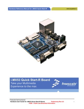
  • 1.     Hardware Reference Manual for i.MX53 Quick Start-R IMX53QSBRM‐R                i.MX53 Quick Start-R Board Take your Multimedia freescale TM  Experience to the max semiconductor   Freescale Semiconductor Hardware User Guide for i.MX53 Quick Start-R Board, Preliminary Rev 0.5 i PUBI – Public Use Business Information  
  • 2.               How to Reach Us:   Home Page: www.freescale.com E-mail: support@freescale.com USA/Europe or Locations Not Listed: Freescale Semiconductor Technical Information Center, CH370 1300 N. Alma School Road Chandler, Arizona 85224 +1-800-521-6274 or +1-480-768-2130 support@freescale.com Information in this document is provided solely to enable system and software Europe, Middle East, and Africa: implementers to use Freescale Semiconductor products. There are no express or Freescale Halbleiter Deutschland GmbH implied copyright licenses granted hereunder to design or fabricate any integrated Technical Information Center circuits or integrated circuits based on the information in this document. Schatzbogen 7 Freescale Semiconductor reserves the right to make changes without further notice 81829 Muenchen, Germany to any products herein. Freescale Semiconductor makes no warranty, representation +44 1296 380 456 (English) or guarantee regarding the suitability of its products for any particular purpose, nor +46 8 52200080 (English) does Freescale Semiconductor assume any liability arising out of the application or +49 89 92103 559 (German) use of any product or circuit, and specifically disclaims any and all liability, including +33 1 69 35 48 48 (French) without limitation consequential or incidental damages. “Typical” parameters that may support@freescale.com be provided in Freescale Semiconductor data sheets and/or specifications can and do vary in different applications and actual performance may vary over time. All Japan: operating parameters, including “Typicals”, must be validated for each customer Freescale Semiconductor Japan Ltd. application by customer’s technical experts. Freescale Semiconductor does not Headquarters convey any license under its patent rights nor the rights of others. Freescale ARCO Tower 15F Semiconductor products are not designed, intended, or authorized for use as 1-8-1, Shimo-Meguro, Meguro-ku, components in systems intended for surgical implant into the body, or other Tokyo 153-0064, Japan applications intended to support or sustain life, or for any other application in which 0120 191014 or +81 3 5437 9125 the failure of the Freescale Semiconductor product could create a situation where support.japan@freescale.com personal injury or death may occur. Should Buyer purchase or use Freescale Semiconductor products for any such unintended or unauthorized application, Buyer Asia/Pacific: shall indemnify and hold Freescale Semiconductor and its officers, employees, Freescale Semiconductor Hong Kong Ltd. subsidiaries, affiliates, and distributors harmless against all claims, costs, damages, Technical Information Center and expenses, and reasonable attorney fees arising out of, directly or indirectly, any 2 Dai King Street claim of personal injury or death associated with such unintended or unauthorized Tai Po Industrial Estate use, even if such claim alleges that Freescale Semiconductor was negligent Tai Po, N.T., Hong Kong regarding the design or manufacture of the part. +800 2666 8080 support.asia@freescale.com Learn More: For more information about Freescale products, please visit www.freescale.com. For Literature Requests Only: Freescale Semiconductor Literature Distribution Center Freescale™ and the Freescale logo are trademarks of Freescale Semiconductor, Inc. P.O. Box 5405 All other product or service names are the property of their respective owners. Denver, Colorado 80217 © Freescale Semiconductor, Inc. 2011. All rights reserved. 1-800-441-2447 or 303-675-2140 Fax: 303-675-2150 LDCForFreescaleSemiconductor@hibbertgroup.com Freescale Semiconductor Hardware User Guide for i.MX53 Quick Start-R Board, Preliminary Rev 0.5 ii PUBI – Public Use Business Information  
  • 3.     Hardware Reference Manual for i.MX53 Quick Start-R IMX53QSBRM‐R    Table of Contents  1.  Introduction .......................................................................................................................................... 1  1.1.  i.MX53‐QUICK START Board Overview ......................................................................................... 1  1.2.  i.MX53‐QUICK START Board Kit Contents ..................................................................................... 2  1.3.  i.MX53 Quick Start Board Revision History ................................................................................... 2  2.  List of Acronyms .................................................................................................................................... 3  3.  Specifications ........................................................................................................................................ 4  3.1.  i.MX535 Processor ........................................................................................................................ 4  3.2.  DDR3 DRAM Memory ................................................................................................................... 7  3.3.  PMIC companion chip: Freescale ‐ MC34708 ............................................................................... 7  3.4.  MicroSD Card Slot (J4)  .................................................................................................................. 7  . 3.5.  SD Card Slot (J5) ............................................................................................................................ 8  3.6.  SATA 7‐pin Data Connector (J7) .................................................................................................... 8  3.7.  VGA Video Output (J8) .................................................................................................................. 8  3.8.  LVDS Video Output (J9) ................................................................................................................. 8  3.9.  Ethernet (J2B)  ............................................................................................................................... 8  . 3.10.  Dual USB Host Connector (J2A)  ................................................................................................ 9  . 3.11.  Micro‐B USB Device Connector (J3) .......................................................................................... 9  3.12.  Audio Input/Output (J6/J18) ..................................................................................................... 9  3.13.  5V Power Connector (J1)......................................................................................................... 10  3.14.  Debug UART Connector (J16) .................................................................................................. 10  3.15.  JTAG Connector (J15) .............................................................................................................. 11  3.16.  Expansion Header (J13) ........................................................................................................... 11  3.17.  User Interface Buttons ............................................................................................................ 12  3.18.  User Interface LED Indicators  ................................................................................................. 12  . 3.19.  PCB Shorting Traces ................................................................................................................ 13  4.  Quick Start Board Connectors and Expansion Port............................................................................. 14  4.1.  Wall 5V Power Jack (J1)  .............................................................................................................. 14  . 4.2.  RJ45 Ethernet Connector (J2B) ................................................................................................... 15  4.3.  VGA DB15 Connector (J8) ........................................................................................................... 16  4.4.  Debug UART DB9 Connector (J16) .............................................................................................. 17  4.5.  Headphone Output Connector (J18) ........................................................................................... 18  4.6.  Microphone Input Connector (J6) ............................................................................................... 19  4.7.  Dual USB Host Jack (J2) ............................................................................................................... 20  Freescale Semiconductor Hardware User Guide for i.MX53 Quick Start-R Board, Preliminary Rev 0.5 iii PUBI – Public Use Business Information  
  • 4.       4.8.  micro‐B USB Device Connector (J3) ............................................................................................ 21  4.9.  SATA 7‐pin Data Connector (J7) .................................................................................................. 22  4.10.  SD Card Connector (J5) ........................................................................................................... 23  4.11.  microSD Card Connector (J4) .................................................................................................. 24  4.12.  20‐pin ARM JTAG Connector (J15) .......................................................................................... 25  4.13.  LVDS Connector (J9) ................................................................................................................ 26  5.  Quick Start Board Architecture and Design ........................................................................................ 27  5.1.  5V Power Supply ......................................................................................................................... 28  5.2.  3.8 V main PMIC input supply ..................................................................................................... 29  5.3.  Freescale MC34708 PMIC ........................................................................................................... 30  5.3.1.  3.8 V Quick Start Power Rails .............................................................................................. 32  5.3.2.  Touch‐Screen Operation ..................................................................................................... 33  5.3.3.  Miscellaneous ..................................................................................................................... 33  5.4.  3.2V Secondary Voltage Regulator ............................................................................................. 34  5.5.  i.MX53 Applications Processor.................................................................................................... 35  5.5.1.  Peripheral Module Logic Voltage Levels ............................................................................. 35  5.5.2.  Boot Mode Operations and Selections ............................................................................... 37  5.5.3.  Clock Signals ........................................................................................................................ 44  5.5.4.  i.MX53 Internal Regulators ................................................................................................. 45  5.5.5.  Watch Dog Timer ................................................................................................................ 45  5.5.6.  Wakeup after User Initiated Standby ................................................................................. 45  5.6.  DDR3 SDRAM Memory  ............................................................................................................... 46  . 5.7.  Micro SD Card Connector  ........................................................................................................... 47  . 5.8.  Full Size SD Card Connector ........................................................................................................ 48  5.9.  VGA Video Output ....................................................................................................................... 49  5.10.  LVDS Video Output.................................................................................................................. 50  5.11.  Expansion Port ........................................................................................................................ 51  5.12.  Audio ....................................................................................................................................... 52  5.13.  Ethernet .................................................................................................................................. 53  5.14.  USB Host connections ............................................................................................................. 54  5.15.  SATA ........................................................................................................................................ 55  5.16.  Debug UART Serial Port........................................................................................................... 56  5.17.  JTAG Operations  ..................................................................................................................... 57  . 6.  Connector Pin‐Outs ............................................................................................................................. 58  7.  Board Accessories ............................................................................................................................... 75  Freescale Semiconductor Hardware User Guide for i.MX53 Quick Start-R Board, Preliminary Rev 0.5 iv PUBI – Public Use Business Information  
  • 5.     Hardware Reference Manual for i.MX53 Quick Start-R IMX53QSBRM‐R  7.1.  HDMI Daughter Card ................................................................................................................... 75  7.2.  LCD Display Daughter Card ......................................................................................................... 77  7.3.  LVDS Display Set (Coming Soon) ................................................................................................. 79  8.  Mechanical PCB Information .............................................................................................................. 81  9.  Board Verification ............................................................................................................................... 83  10.  Troubleshooting .............................................................................................................................. 87  10.1.  PMIC Voltage Rail Test Points ................................................................................................. 88  11.  Known Issues  .................................................................................................................................. 90  . 12.  PCB Component Locations .............................................................................................................. 91  13.  Schematics ...................................................................................................................................... 96  14.  Bill of Materials ............................................................................................................................. 111  15.  PCB information ............................................................................................................................ 118            Freescale Semiconductor Hardware User Guide for i.MX53 Quick Start-R Board, Preliminary Rev 0.5 v PUBI – Public Use Business Information  
  • 6.           List of Figures  Figure 1.  DC Power Jack ......................................................................................................................... 14  Figure 2.  RJ45 Ethernet Connector ........................................................................................................ 15  Figure 3.  VGA Connector  ....................................................................................................................... 16  . Figure 4.  Debug UART Connector .......................................................................................................... 17  Figure 5.  Headphone Output Connector ............................................................................................... 18  Figure 6.  Microphone Connector (J6) .................................................................................................... 19  Figure 7.  Dual USB Host Connectors (J2) ............................................................................................... 20  Figure 8.  Micro‐B USB Device Connector (J3) ........................................................................................ 21  Figure 9.  SATA Data Connector (J7) ....................................................................................................... 22  Figure 10.  SD Card Connector (J5) ....................................................................................................... 23  Figure 11.  MicroSD Card Connector (J4) .............................................................................................. 24  Figure 12.  JTAG Connector (J15) .......................................................................................................... 25  Figure 13.  LDVS Connector (J9) ............................................................................................................ 26  Figure 14.  i.MX53 Smart‐Start Block Diagram (modify) ....................................................................... 27  Figure 15.  5V Main input Power Circuit. .............................................................................................. 28  Figure 16.  PMIC Main input Power Supply. ......................................................................................... 29  Figure 18.  Boot Mode Resistor Locations TOP  .................................................................................... 42  . Figure 19.  Boot Mode Resistor Locations BOTTOM ............................................................................ 43  Figure 20.  Clock Source Locations ........................................................................................................ 44  Figure 21.  Power Jack (J1) .................................................................................................................... 59  Figure 22.  Micro‐B USB Connector (J3) ................................................................................................ 59  Figure 23.  Ethernet/Dual USB Conn (J2) .............................................................................................. 60  Figure 24.  Headphone Connector (J18) ............................................................................................... 61  Figure 25.  Microphone Connector (J6) ................................................................................................ 61  Figure 26.  VGA DB15 Connector (J8) ................................................................................................... 62  Figure 27.  LVDS Connector (J9) ............................................................................................................ 63  Figure 28.  SATA Data Connector (J7) ................................................................................................... 64  Figure 29.  SD Card Connector (J5) ....................................................................................................... 65  Figure 30.  microSD Card Connector (J4) .............................................................................................. 66  Figure 31.  Debug UART Connector (J16) .............................................................................................. 67  Freescale Semiconductor Hardware User Guide for i.MX53 Quick Start-R Board, Preliminary Rev 0.5 vi PUBI – Public Use Business Information  
  • 7.     Hardware Reference Manual for i.MX53 Quick Start-R IMX53QSBRM‐R  Figure 32.  JTAG Connector (J15) .......................................................................................................... 68  Figure 33.  Expansion Port (J13) ............................................................................................................ 69  Figure 34.  Expansion Port .................................................................................................................... 70  Figure 35.  Optional HDMI Daughter Card ............................................................................................ 75  Figure 36.  MCIMX28LCD 4.3” WVGA Display Daughter Card .............................................................. 77  Figure 37.  LVDS Display Kit................................................................................................................... 79  Figure 38.  Quick Start Board Dimensions ............................................................................................ 81  Figure 39.  Ethernet Loopback Cable .................................................................................................... 86  Figure 40.  Regulator Output Capacitor Positions Bottom ................................................................... 88  Figure 41.  Regulator Output Capacitor Positions Top ......................................................................... 89  Figure 42.  Major Component Highlights Top ....................................................................................... 92  Figure 43.  Major Component Highlights Bottom ................................................................................. 93  Figure 44.  Assembly Drawing Top ........................................................................................................ 94  Figure 45.  Assembly Drawing Bottom  ................................................................................................. 95  . Figure 46.  Main 5V INPUT .................................................................................................................... 97  Figure 47.  MX53 POWER ...................................................................................................................... 98  Figure 48.  MX53 DDR3 MEMORY  ........................................................................................................ 99  . Figure 49.  MX53 CONTROL ................................................................................................................ 100  Figure 50.  MX53 USB  ......................................................................................................................... 101  . Figure 51.  MX53 SD INTERFACE ......................................................................................................... 102  Figure 52.  MX53 AUDIO ..................................................................................................................... 103  Figure 53.  MX53 SATA ........................................................................................................................ 104  Figure 54.  MX53 VGA ......................................................................................................................... 105  Figure 55.  MX53 ETHERNET ............................................................................................................... 106  Figure 56.  EXPANSION HEADER ......................................................................................................... 107  Figure 57.  MC34708  PMIC I  .............................................................................................................. 108  . Figure 58.  MC34708 PMIC II .............................................................................................................. 109  Figure 59.  DEBUG, ACCELEROMETER ................................................................................................. 110  Figure 60.  Top Etch Layer ................................................................................................................... 119  Figure 61.  Second Etch Layer ............................................................................................................. 120  Figure 62.  Third Etch Layer ................................................................................................................ 121  Figure 63.  Fourth Etch Layer .............................................................................................................. 122  Figure 64.  Fifth Etch Layer.................................................................................................................. 123  Freescale Semiconductor Hardware User Guide for i.MX53 Quick Start-R Board, Preliminary Rev 0.5 vii PUBI – Public Use Business Information  
  • 8.       Figure 65.  Sixth Etch Layer ................................................................................................................. 124  Figure 66.  Seventh Etch Layer ............................................................................................................ 125  Figure 67.  Bottom Etch Layer ............................................................................................................. 126  Figure 68.  Soldermask Top ................................................................................................................. 127  Figure 69.  Soldermask Bottom  .......................................................................................................... 128  . Figure 70.  Pastemask Top .................................................................................................................. 129  Figure 71.  Pastemask Bottom ............................................................................................................ 130  Figure 72.  Silkscreen Top ................................................................................................................... 131  Figure 73.  Silkscreen Bottom ............................................................................................................. 132          Freescale Semiconductor Hardware User Guide for i.MX53 Quick Start-R Board, Preliminary Rev 0.5 viii PUBI – Public Use Business Information  
  • 9.     Hardware Reference Manual for i.MX53 Quick Start-R IMX53QSBRM‐R      List of Tables    Table 1.  Regulator Power up Sequence ................................................................................................ 31  Table 2.  Quick Start Board Power Supply Rails ..................................................................................... 32  Table 3.  Port ID Resistor Values ............................................................................................................ 33  Table 4.  Module Voltage Supplies ........................................................................................................ 36  Table 5.  BOOT_MODE pin Settings ....................................................................................................... 37  Table 6.  BOOT_CFG Word1  .................................................................................................................. 37  . Table 7.  BOOT_CFG Word2  .................................................................................................................. 37  . Table 8.  BOOT_CFG Word3  .................................................................................................................. 38  . Table 9.  Boot Mode Resistors TOP ....................................................................................................... 42  Table 10.  Boot Mode Resistors BOTTOM ............................................................................................... 43  Table 11.  DDR3 SDRAM Chip Organization  ............................................................................................ 46  . Table 12.  Micro‐SD Card Boot Options ................................................................................................... 47  Table 13.  Full Size SD Card Boot Options ................................................................................................ 48  Table 14.  SATA Boot Mode Configuration Table. ................................................................................... 55  Table 15.  Terminal Setting Parameters .................................................................................................. 56  Table 16.  Expansion Port Pin‐Mux Table ................................................................................................ 71  Table 17.  Expansion Port Pin‐Mux Table (con) ....................................................................................... 72  Table 18.  Expansion Port Pin‐Mux Table (con) ....................................................................................... 73  Table 19.  Expansion Port Pin‐Mux Table (con) ....................................................................................... 74  Table 20.  Board Stack up information .................................................................................................... 82  Table 21.  Problem Resolution Table ....................................................................................................... 87  Table 22.  Output Capacitors and Values BOTTOM ................................................................................. 88  Table 23.  Output Capacitors and Values TOP ......................................................................................... 89  Table 24.  Generic Resistors .................................................................................................................. 112  Table 25.  Generic Capacitors ................................................................................................................ 113  Table 26.  Specified Components .......................................................................................................... 116  Table 27.  Non‐Populated Components ................................................................................................ 117      Freescale Semiconductor Hardware User Guide for i.MX53 Quick Start-R Board, Preliminary Rev 0.5 ix PUBI – Public Use Business Information  
  • 10.     Hardware Reference Manual for i.MX53 Quick Start     1. Introduction    This document is the Hardware Reference Manual for the i.MX53 Quick Start board based on the  Freescale Semiconductor i.MX53 Applications Processor. This board is fully supported by Freescale  Semiconductor. This Manual includes system setup and debugging, and provides detailed information  on the overall design and usage of the i.MX53 Quick Start board from a Hardware Systems perspective.  1.1. i.MX53­QUICK START Board Overview    The Quick Start Board is an i.MX535 platform designed to showcase many of the most commonly used  features of the i.MX535 Applications Processor in a small, low cost package. The MCIMX53‐START is an  entry level development board and a near perfect subset of its larger sister board, the MCIMX53SMD,  which is available as a full, near‐form factor tablet.    Developers can start working with code on the  Quick Start board, and then port it over to the SMD Tablet if additional features are desired. This gives  the developer the option of becoming familiar with the i.MX535 Applications Processor before investing  a large amount or resources in more specific designs. Features of the i.MX53 Quick Start board are:    Processor:  Freescale Applications Processor     MCIMX535DVV1C  DRAM Memory:  Micron 8Gb DDR3 SDRAM       MT41J128M16HA‐187E:D  PMIC:  Freescale PMIC        MC34708  Mass Storage:  5 in 1 SD/MMC/SDIO Card Connector    microSD Card Connector    7‐pin SATA Data Connector  Video Output:  15‐Pin D‐Sub VGA Connector    30‐Pin LVDS Connector  Ethernet:  RJ‐45 Connector for 10/100 Base‐T  USB:  Dedicated HS USB 2.0 Standard‐A Host Connector    Shared HS USB 2.0 Standard ‐ Host and Micro‐B Device Connectors  Audio Connectors:  3.5mm Stereo Head Phone output    3.5mm Mono‐Microphone input     Mono Head Phone (right channel) output  Power Connectors:  5V/2.0A, 2.1 mm Barrel Connector  Debug Connectors:  9‐Pin D‐Sub Debug UART Connector    20‐Pin Standard ARM JTAG Connector  Expansion Header:  120‐Pin Header (Populated) to Support 1 of the following:    Optional HDMI Output Daughter Card (orderable)    Optional WVGA and WQVGA LCD Display Daughter Cards (orderable)    Camera Daughter Card (custom)    SDIO Based WiFi Daughter card (custom)  User Interface Buttons:  Power, Reset, 2 User‐Defined Buttons  Indicators:  8 Status LEDs – External Power, PMIC ON, Fault Condition, and more  Freescale Semiconductor Hardware User Guide for i.MX53 Quick Start-R Board, Preliminary Rev 0.5 1 PUBI – Public Use Business Information  
  • 11.         Li‐ION Battery Connector:  3‐Pin Header (unpopulated) for Li‐ION Battery for Low Power Operation  Coin Cell:  Connection point for 2‐Pin Coin Cell (unpopulated) for RTC Operation  PCB:  3.0 inch x 3.0 inch (76.2 mm x 76.2 mm), 10 ‐ layer board    1.2. i.MX53­QUICK START Board Kit Contents    The i.MX53‐Quick Start Board comes with the following items:  i.MX53‐QUICK START Board  microSD Card preloaded with Ubuntu Demonstration Software  USB Cable (Standard‐A to Micro‐B connectors)  5V/2.0A Power Supply  Quick Start Guide  Documentation DVD    1.3. i.MX53 Quick Start Board Revision History      MCIMX53‐START‐R Board  Rev B – Production (Silicon: i.MX53 Rev 2.1, MC34708 Rev 2.4)    The board assembly version will be printed on a label, usually attached to the side of the Ethernet/Dual  USB Connector (J2). The assembly version will be the letter designation following the schematic revision:    MCIMX53‐START‐R    700‐27104 REV _B      Freescale Semiconductor Hardware User Guide for i.MX53 Quick Start-R Board, Preliminary Rev 0.5 2 PUBI – Public Use Business Information  
  • 12.     Hardware Reference Manual for i.MX53 Quick Start     2. List of Acronyms    The following acronyms will be used throughout this document.    AC97    ‐ Audio Codec ‘97  CMC    ‐ Common Mode Choke  CODEC    ‐ Compression/Decompression  DDR     ‐ Double Data Rate  DNP    ‐ Do Not Populate  HDMI    ‐ High Definition Multimedia Interface  I2C    ‐ Inter‐Integrated Circuit  I2S    ‐ Integrated Interchip Sound  IC     ‐ Integrated Circuit  IDE     ‐ Integrated Debug Environment  LAN     ‐ Local Area Network  LCB    ‐ i.MX53 Smart‐Start  LCD    ‐Liquid Crystal Display  LPDDR2  ‐ Low Power DDR2  MMC    ‐ Multi Media Card  PMIC    ‐ Power Management Companion IC  RMII    ‐ Reduced Media Independent Interface  RTC    ‐ Real‐Time Clock  SDRAM   ‐ Synchronous Dynamic Random Access Memory  SD    ‐ Secure Digital  SPI    ‐ Serial Peripheral Interface  SSI    ‐ Synchronous Serial Interface  ULPI    ‐ UTMI Low Pin Interface  USB     ‐ Universal Serial Bus  UTMI    ‐ Universal Transceiver Macrocell Interface  WDOG    ‐ Watch Dog  WLAN     ‐ Wireless LAN      Freescale Semiconductor Hardware User Guide for i.MX53 Quick Start-R Board, Preliminary Rev 0.5 3 PUBI – Public Use Business Information  
  • 13.             3. Specifications  3.1. i.MX535 Processor  The i.MX535 Applications Processor (AP) is based on ARM Cortex‐A8TM Platform, which has the following  features:  MMU, L1 Instruction and L1 Data Cache  Unified L2 cache  Target frequency of the core (including Neon, VFPv3 and L1 Cache): 1.0 GHz  Neon coprocessor (SIMD Media Processing Architecture) and Vector Floating Point (VFP‐ Lite) coprocessor supporting VFPv3  TrustZone    The memory system consists of the following components:  Level 1 Cache:  o Instruction (32 Kbyte)  o Data (32 Kbyte)  Level 2 Cache:  o Unified instruction and data (256 Kbyte)  Level2 (internal) memory:  o Boot ROM, including HAB (64 Kbyte)  o Internal multimedia/shared, fast access RAM (128 Kbyte)  o Secure/non‐secure RAM (16 Kbyte)  External memory interfaces:  o 16/32‐bit DDR2‐800, LV‐DDR2‐800 or DDR3‐800 up to 2 Gbyte  o 32 bit LPDDR2  o 8/16‐bit NAND SLC/MLC Flash, up to 66 MHz, 4/8/14/16‐bit ECC  o 16‐bit NOR Flash. All WEIMv2 pins are muxed on other interfaces (data with NFC  pins). I/O muxing logic selects WEIMv2 port, as primary muxing at system boot.  o 16‐bit SRAM, cellular RAM  o Samsung One NANDTM and managed NAND including eMMC up to rev 4.4 (in  muxed I/O mode)    The i.MX53 system is built around the following system on chip interfaces:  64‐bit AMBA AXI v1.0 bus – used by ARM platform, multimedia accelerators (such as  VPU, IPU, GPU3D, GPU2D) and the external memory controller (EXTMC) operating at  200 MHz.  32‐bit AMBA AHB 2.0 bus – used by the rest of the bus master peripherals operating at  133 MHz.  32‐bit IP bus – peripheral bus used for control (and slow data traffic) of the most system  peripheral devices operating at 66 MHz.    The i.MX53 makes use of dedicated hardware accelerators to achieve state‐of‐the‐art multimedia  performance. The use of hardware accelerators provides both high performance and low power  consumption while freeing up the CPU core for other tasks.      Freescale Semiconductor Hardware User Guide for i.MX53 Quick Start-R Board, Preliminary Rev 0.5 4 PUBI – Public Use Business Information  
  • 14.     Hardware Reference Manual for i.MX53 Quick Start     The i.MX53 incorporates the following hardware accelerator:  VPU, version 3 – video processing unit  GPU3D – 3D graphics processing unit, OpenGL ES 2.0, version 3, 33 Htri/s, 200 Mpix/s,  and 800 Mpix/s z‐plane performance, 256 Kbyte RAM memory.  GPU2D – 2D graphics accelerator, OpenVG 1.1, version 1, 200 Mpix/s performance.  IPU, version 3M – image processing unit  ASRC – asynchronous sample rate converter    The I.MX53 includes the following interfaces to external devices:    NOTE  Not all the interfaces are available simultaneously depending on I/O multiplexer configuration.  Hard disk drives:  o PATA, up to U‐DMA mode 5, 100 MByte/s  o SATA II, 1.5 Gbps  Displays:  o Five interfaces available. Total rate of all interfaces is up to 180 Mpixels/s, 24  bpp. Up to two interfaces may be active as once.  o Two parallel 24‐bit display ports. The primary port is up to 165 Mpix/s (for  example, UXGA @ 60 Hz).  o LVDS serial ports: one dual channel port up to 165 Mpix/s or two independent  single channel ports up to 85 MP/s (for example, WXGA @ 60 Hz) each.  o TV‐out/VGA port up to 150 Mpix/s (for example, 1080p60).  Camera sensors:  o Two parallel 20‐bit camera ports. Primary up to 180‐MHz peak clock frequency,  secondary up to 120‐MHz peak clock frequency.  Expansion cards:  o Four SD/MMC card ports: three supporting 416 Mbps (8‐bit i/f) and one  enhanced port supporting 832 Mbps (8‐bit, eMMC 4.4)  USB  o High‐speed (HS) USB 2.0 OTG (up to 480 Mbps), with integrated HS USB PHY  o Three USB 2.0 (480 Mbps) hosts:  High‐speed host with integrated on‐chip high speed PHY  Two high‐speed hosts for external HS/FS transceivers through  ULPI/serial, support IC‐USB      Freescale Semiconductor Hardware User Guide for i.MX53 Quick Start-R Board, Preliminary Rev 0.5 5 PUBI – Public Use Business Information  
  • 15.         Miscellaneous interfaces:  o One‐wire (OWIRE) port  o Three I2S/SSI/AC97 ports, supporting up to 1.4 Mbps, each connected to audio  multiplexer (AUDMUX) providing four external ports.  o Five UART RS232 ports, up to 4.0 Mbps each. One supports 8‐wire, the other  four support 4‐wire.  o Two high speed enhanced CSPI (ECSPI) ports plus one CSPI port  o Three I2C ports, supporting 400 kbps.  o Fast Ethernet controller, IEEE1588 V1 compliant, 10/100 Mbps  o Two controller area network (FlexCAN) interfaces, 1 Mbps each  o Sony Philips Digital Interface (SPDIF), Rx and Tx  o Enhanced serial audio interface (ESAI), up to 1.4 Mbps each channel  o Key pad port (KPP)  o Two pulse‐width modulators (PWM)  o GPIO with interrupt capabilities  o Secure JTAG controller (SJC)    The system supports efficient and smart power control and clocking:  Supporting DVFS (Dynamic Voltage and Frequency Scaling) and DPTC (Dynamic Process  and Temperature Compensation) techniques for low power modes.  Power gating SRPG (State Retention Power Gating) for ARM core and Neon  Support for various levels of system power modes.  Flexible clock gating control scheme  On‐chip temperature monitor  On‐chip oscillator amplifier supporting 32.768 kHZ external crystal  On‐chip LDO voltage regulators for PLLs    Security functions are enabled and accelerated by the following hardware:  ARM TrustZone including the TZ architecture (separation of interrupts, memory  mapping, and so on)  Secure JTAG controller (SJC) – Protecting JTAC from debug port attacks by regulating or  blocking the access to the system debug features.  Secure real‐time clock (SRTC) – Tamper resistant RTC with dedicated power domain and  mechanism to detect voltage and clock glitches.  Real‐time integrity checker, version 3 (RTICv3) – RTIC type 1, enhanced with SHA‐256  engine  SAHARAv4 Lite – Cryptographic accelerator that includes true random number  generator (TRNG)  Security controller, version 2 (SCCv2) – Improved SCC with AES engine,  secure/nonsecure RAM and support for multiple keys as well as TZ/non‐TZ separation.  Central Security Unit (CSU) – Enhancement for the IIM (IC Identification Module). CSU is  configured during boot and by e‐fuses and determines the security level operation  mode as well as the TrustZone (TZ) policy.  Advanced High Assurance BOOT (A‐HAB) – HAB with the next embedded enhancements:        SHA‐256, 2046‐bit RSA key, version control mechanism, warm boot, CSU and TZ  initialization.  Freescale Semiconductor Hardware User Guide for i.MX53 Quick Start-R Board, Preliminary Rev 0.5 6 PUBI – Public Use Business Information  
  • 16.     Hardware Reference Manual for i.MX53 Quick Start     3.2. DDR3 DRAM Memory    The i.MX53‐Quick Start board uses four 2‐Gigabit DDR3 SDRAM ICs manufactured by Micron for a total  onboard RAM memory of 1 GigaByte. The SDRAM data width for each IC is 16‐bits. The chips are  arranged in pairs that are controlled by each of the two chip select pins to form 32‐bit words for the  i.MX53 CPU. On Die Termination (ODT) functionality has been implemented on the board, as well as the  ability to separate out the I/O Voltage Supply from the main SDRAM Voltage Supply if desired.  3.3. PMIC companion chip: Freescale ­ MC34708    The MC34708 Power Management integrated Circuit is an integrated solution to supply power to  i.MX53 based systems; it is housed in a 13 x 13mm, 0.8 mm pitch or an 8 x 8 mm, 0.5 mm Pitch; 206  balls MAPBGA package. The main characteristics featured on the Quick Start board are listed below:  Features    Power supply Resources  o 6 multi‐mode buck regulators   o For direct supply of the processor core  Memory  Peripherals  o 8 regulators with internal and external pass devices for thermal budget  optimization  o Boost regulator   Dual input switching charger for single cell Li‐Ion battery, supports universal charging  standard for selection of optimal charging profile  Dual path charger design enables power‐on with a dead/ no battery  Coulomb counter support module for fuel gauge monitoring  USB/UART/Audio switching for mini‐micro USB connector  10‐bit ADC for monitoring battery and other inputs  Real time clock and crystal oscillator circuitry with coin cell backup/charger  SPI/I2C bus for control and register interface    3.4. MicroSD Card Slot (J4)    The microSD Card slot is used as the primary means to boot the Quick Start board. The power source for  the microSD Card slot is DCDC_3V2. The microSD Card slot is not normally configured with a card detect  feature. The MicroSD Card slot can be configured to boot from a MMCmicro card with an alternate boot  option setting (see section on Boot Options).        Freescale Semiconductor Hardware User Guide for i.MX53 Quick Start-R Board, Preliminary Rev 0.5 7 PUBI – Public Use Business Information  
  • 17.         3.5. SD Card Slot (J5)    The SD Card slot is a 5‐in‐1 SD/MMC connector that acts as a secondary external memory media slot.  The power source for the SD Card Slot is the auxiliary LDO regulator (DCDC_3V2). The SD Card slot can  be configured as the boot source with an alternate boot option setting, as well as being configured for  either SD or MMC card operation (see section on Boot Options). The SD Card Slot supports full 8‐bit  parallel data transfers and can support SDIO cards (WiFi, BT, etc) designed to fit in a standard SD card  slot. The Quick Start board has specifically been tested with an Atheros SD‐25 WiFi card.    3.6. SATA 7­pin Data Connector (J7)    The SATA connector provides the means to connect an external SATA memory device to the Quick Start  board. Commonly, this would be an External hard drive or a DVD/CD reader. Power for the SATA device  needs to be supplied externally by the user via a 12‐pin power connector. It is possible to boot from a  SATA drive by making OTP fuse changes. Once the fuse changes are made, they cannot be reversed.    3.7. VGA Video Output (J8)    A standard VGA signal is output directly from the i.MX53 Processor with minimum external components  required. Power for the TVE module of the i.MX535 Processor is supplied by VDAC of the PMIC and is set  to 2.75V. The VGA output supports a variety of video formats up to 150 Mega‐Pixels per second. Level  shifters are required on the Horizontal and Vertical Synchronization signals as well as the VGA I2C  communications signals in order to meet VGA specifications.    3.8. LVDS Video Output (J9)    The LVDS module of the i.MX53 Processor is connected to a 30‐pin LVDS connector. While the i.MX53  Processor is capable of outputting to two separate LVDS displays, only one connector is pinned out on  the Quick Start board. The pin outs on the LVDS connector match the optional cable and 10” HannStar  LVDS display that can be purchased optionally from Freescale. The single LVDS connector will support  video formats up to 165 Mega‐Pixels per second. The power source for the LVDS module is a switchable  output of the VBUCKPERI DCDC converter. This rail is shared with the SATA module and the USB module.  If these modules are not being used, the PMIC can be programmed to turn off power to these three  modules without affecting other 2.5V supplies to the remainder of the i.MX53 Applications Processor.    3.9. Ethernet (J2B)    The i.MX53 Processor Fast Ethernet Module outputs RMII formatted signals to an external Ethernet PHY.  The processor is capable of 10/100 Base‐T speeds. The Quick Start board uses the SMSC LAN8720A  Ethernet Transceiver in a QFN‐24 package. 3.2V power is supplied to the Ethernet IC from the external  LDO regulator. The output of the Ethernet PHY is connected to an RJ45 jack with integrated magnetic.    Freescale Semiconductor Hardware User Guide for i.MX53 Quick Start-R Board, Preliminary Rev 0.5 8 PUBI – Public Use Business Information  
  • 18.     Hardware Reference Manual for i.MX53 Quick Start   3.10. Dual USB Host Connector (J2A)    The USB module of the i.MX53 Processor provides two high speed USB PHYs that are connected to each  of the USB‐A Host Jacks on connector J2. One PHY provides Host‐only functionality and is connected to  the upper USB jack on the connector tower. The second PHY is USB 2.0 OTG capable and is connected to  the lower USB jack on the connector tower. Both jacks receive 5V power directly from the 5V Wall  Power Supply, via a FET that can be controlled by software, and a 1.1A Poly‐fuse. The PMIC provides an  over‐voltage functionality to limit voltage applied to the USB jack in the event that a DC Power Supply  other than the original supply provided is used. Also, there is no current regulating device to limit  current supplied to each jack, other than the Poly‐fuse.    NOTE  The lower USB Host Jack is cross connected with the Micro‐B USB Device connector. This was done as a  convenience to the user as cables with micro‐A plugs are still uncommon at the time the board was  designed. The USB OTG PHY will switch to ‘device’ mode if a USB Host is attached to the micro‐B  connector with a cable. This design is not recommended for release to the general electronics consumer  population. This board has not been tested for USB compliance.    3.11. Micro­B USB Device Connector (J3)    The micro‐B USB connector is connected to the USB OTG PHY on the i.MX53 Processer, and is also  connected to the Lower USB Host Jack on the connector tower. The connector’s external USB 5V power  pin is connected to the USB_OTG_ID pin, which is normally pulled to ground via a 3.3K Ohm resistor.  When a powered USB Host device is attached to the micro‐B USB connector, the USB_OTG_ID pin is  pulled high and sends a signal to the USB OTG PHY to operate in device mode.  The connector’s external  USB 5V power pin is not connected to the PMIC, or any other power rails on the Quick Start board.  Therefore, it is not possible to supply power to the Quick Start board via the USB connections.    3.12. Audio Input/Output (J6/J18)    Analog audio input and output are provided by Freescale’s Low Power Stereo Codec, SGTL5000. The  audio codec is connected to the i.MX53 Applications Processor via 4‐wire I2S communications, utilizing  the AUDMUX5 port of the processor. The audio codec’s Headphone Amp provides up to 58 mW output  to 16‐Ohm headphones at a typical SNR of 98 dB and THD+N of ‐86 dB. Typical power consumption is  11.6 mW. In addition, the audio codec can perform several enhancements to the output including virtual  surround, added bass and three different types of equalization. The Microphone Input module of the  Stereo Codec is also used, with the microphone input connected to the tip pin of the Microphone Jack  (J6). Microphone Bias voltage is applied on the Quick Start board and not as a separate connection to  the Microphone Jack. If the user desires to use a combined microphone, mono headphone device, the  ferrite bead on L25 can be moved to the L22 pads, redirecting the right channel output to the  Microphone Jack. A 2.5mm to 3.5mm adapter may be necessary to convert the microphone, mono  headphone device to fit the Microphone Jack. On both the Headphone Jack and Microphone jack, a  fourth pin is used to detect the insertion of a plug into either jack. When a standard 3‐pin device is  inserted into the 4‐pin jack, the detect line is grounded, indicating to the i.MX53 Processor that the plug  has been inserted.  Freescale Semiconductor Hardware User Guide for i.MX53 Quick Start-R Board, Preliminary Rev 0.5 9 PUBI – Public Use Business Information  
  • 19.           3.13. 5V Power Connector (J1)    A 2.0mm x 6.5mm barrel connector is used which should fit standard DC Plugs with an inner dimension  of 2.1mm and an outer dimension of 5.5mm. If an alternate power supply is used (not the original,  supplied power supply), it should supply no more than 5.25V / 3A output. In between the Power  Connector and the isolation FET is a single blow, fast acting fuse to protect the Quick Start board from  an over current situation fault. If a Wall Power Supply is properly connected to the Quick Start board,  and the green 5V power LED indicator is not lit, it could mean that either the fuse has been blown, or  that the voltage output of the power supply is too high.    3.14. Debug UART Connector (J16)    UART1 of the i.MX53 Processor is connected to an RS‐232 output to be used as a debug output for the  developer. The Transmit (TX) and Receive (RX) signals are sent through two 1.8V to 3.2V level shifters to  convert the logic signal voltages to the correct values for the Sipex SP3232 RS‐232 transceiver. The CTS  and RTS signals are not used on the Quick Start board. The RS‐232 transceiver receives its power from  the external 3.2V LDO Regulator. If the output of the regulator is turned off for power savings measures,  debug output will be lost.    If the designer wishes to use the port as an Applications UART Port, changes can be made in software to  reconfigure the port. A male‐to‐male gender changer can be used to properly convert the port.    To access the debug data output during development, connect the Debug UART Connector to a suitable  host computer and open a terminal emulation program (ie, Teraterm or HyperTerminal). Proper settings  for the terminal program are:  BAUD RATE:     115,200  DATA:      8 bit  PARITY:     None  STOP BIT:    1‐bit  FLOW CONTROL:  None        Freescale Semiconductor Hardware User Guide for i.MX53 Quick Start-R Board, Preliminary Rev 0.5 10 PUBI – Public Use Business Information  
  • 20.     Hardware Reference Manual for i.MX53 Quick Start   3.15. JTAG Connector (J15)    A standard 20‐pin ARM JTAG connector is provided on the Quick Start board. Logic signals to the JTAG  connector are 1.8V signals. A 1.8V reference signal is provided to pin 1 of the connector so that the  attached JTAG tool can automatically configure the logic signals for the right voltage. If the JTAG tool  does not have an automatic logic voltage sense, make sure that the tool is configured for 1.8V logic.    JTAG tools that have been specifically tested with the Quick Start board are:  JTAG Commander (Macraigor)  DS‐5 and RealView (ARM Ltd.)  Trace32 (Lauterbach)  J‐Link (Segger/Codesourcery)  J‐Link (IAR)    3.16. Expansion Header (J13)      A 120‐pin Expansion Port Header is provided on the Quick Start board for use with many optionally  expansion boards available from Freescale, or for custom designed boards made be the developer. At  the time of initial production, the following expansion boards are available from Freescale:  MCIMXHDMICARD    HDMI signal output daughter card  MCIMX28LCD      4.3” WVGA Touch Panel LCD Display    The Expansion Port makes the following features of the i.MX53 Processor available to be used on a  custom built expansion card:  Two Serial Peripheral Interfaces (SPI)      CSPI, eCSDPI2  Two I2S/SSI/AC97 Ports         AUDMUX4, AUDMUX5  Two Inter‐Integrated Circuits (I2C)      I2C1, I2C2  2 UARTs            UART4, UART5  SPDIF Audio  USB ULPI Port            USBH2  24‐bit Data and display control signals  Resistive Touch Screen Interface  Various Voltage rails          Freescale Semiconductor Hardware User Guide for i.MX53 Quick Start-R Board, Preliminary Rev 0.5 11 PUBI – Public Use Business Information  
  • 21.         3.17. User Interface Buttons          There are four user interface buttons on the Quick Start board. Their functionality is as follows:    POWER:   In the ‘Power Off’ state, momentarily pressing the POWER button will begin the PMIC   power on cycle. The PMIC supplied voltage rails will come up in the proper sequence to  power the i.MX53 Processor. When the processor is fully powered, the boot cycle will be  initiated.    In the ‘Power On’ state, momentarily pressing the POWER button will send a signal to a  GPIO port for user defined action, but will not initiate a hardware shutdown.    In the ‘Power On’ state, holding the power button down for greater than 5 seconds will  result in the PMIC initiating a shutdown to the ‘Off’ power condition. This will also be  the result from the ‘Power Off’ state as the PMIC will transition into the ‘Power On’  state and will still see the POWER button as held down.    RESET:   Pressing the RESET button for 4s during the ‘Power On’ state will force the i.MX53  Applications  Processor to turn off, and reinitiate a boot cycle from the Processor Power  Off state after one second of the Power off.     USERDEF1:  These two buttons are user defined buttons attached to PATA_DATA14 (P6) for   USERDEF2:  USERDEF1 and PATA_DATA15 (P5) for USERDEF2. The two GPIO pins are normally pulled   high by an internal resistor. The two buttons function by connecting the pins to ground,  thus inserting a low signal. The developer is left to determine the actions of these two  pins in code. Sample codes do not assign functionality to either pin.    3.18. User Interface LED Indicators    There are eight LED status indicators located next to the microSD card connector. These LEDs have the  following functions:    5V:    The 5V status LED (D1) is a Green LED connected directly to the 5V_MAIN power rail.   This LED indicates that 5V wall power is being properly supplied to the Quick Start  board. If this light is not lit, it would indicate one of three problems:    Fuse F1 has been blown and needs to be replaced.  Voltage from the wall supply is greater than 5.5V and the over voltage protection  feature is disabling power to the board.  The DC Power supply is not plugged in or malfunctioning.    PMIC:  The PMIC status LED (D9) is a Green LED gated by the DCDC_3V2 power rail. This LED  indicates that there is an input supply connected to the system.    USER:    The User status LED (D16) is a Green LED gated by the PATA_DATA1 (L3) GPIO pin. The  Freescale Semiconductor Hardware User Guide for i.MX53 Quick Start-R Board, Preliminary Rev 0.5 12 PUBI – Public Use Business Information  
  • 22.     Hardware Reference Manual for i.MX53 Quick Start   developer is left to determine the action of this pin in code. Sample codes do not assign  functionality to the pin. The LED comes on by default when the processor starts up.    FLT:    The FLT status LED (D14) is a Red LED gated by the NVDD_FAULT signal from the PMIC.   The LED will turn on anytime the PMIC is not outputting the requested voltages or when  the PMIC senses a fault condition and will begin to power down the voltage rails. This  may aid in trouble shooting power problems if both the PMIC and FLT LEDs are on at the  same time, it indicates that the PMIC is causing a shutdown based on a fault it has  sensed.    3.3V:    The 3.3V status LED (D10) is a Blue LED gated by the External Regulator 3.2V power rail.   This power rail can be turned off by software for power savings measures. This LED  provides an easy visual recognition as to the status of this bus.    SATA:    The SATA status LED (D11) is a Blue LED gated by the SATA_1V3 (VLDO5) power rail.   This power rail can be turned off by software for power savings measures. This LED  provides an easy visual recognition as to the status of this bus.    VGA:    The VGA status LED (D12) is a Blue LED gated by the TVDAC_2V75 (VLDO7) power rail.   This power rail can be turned off by software for power savings measures. This LED  provides an easy visual recognition as to the status of this bus.    LCD:    The LCD status LED (D13) is a Blue LED gated by the LCD_3V2 power rail.   Normally the LCD_3V2 power rail receives power directly from the DCDC_3V2 power  rail, but the LCD can also be configured to receive power from VIOHI_2V772 (VLDO4). In  the alternate voltage supply configuration, this LED will provide visual recognition as to  the status of the LCD bus.    3.19. PCB Shorting Traces    On the Quick Start PCB, there are 29 sets of standard footprints with a copper trace between them to  short the two pads together. The PCB is produced with these pads unpopulated. These shorting traces  are placed throughout the PCB at locations in line with major power rails and critical components. The  purpose of these shorting traces it to allow the skilled developer to manually cut the trace between the  pads to either:    1. Isolate power to major subsystems or components.  2. Install small value precision resistors to measure current consumption of major subsystems.  3. Or reconfigure power sources to subsystems or components using wires soldered to the  pads.    To restore a shorting trace back to normal after the trace is cut, it is only necessary to solder a Zero Ohm  resistor to the pads.        Freescale Semiconductor Hardware User Guide for i.MX53 Quick Start-R Board, Preliminary Rev 0.5 13 PUBI – Public Use Business Information  
  • 23.         4. Quick Start Board Connectors and Expansion Port    The Quick Start board provides a number of connectors for a variety of inputs and outputs to and from  the board. The following subsections describe these connections in detail.    4.1. Wall 5V Power Jack (J1)    The 5V/2A AC‐to‐DC power supply that comes with the Quick Start board is plugged into the Power Jack  (J1) on the board as show in Figure 1. If the original power supply is lost, it is possible to use a substitute  power supply for the Quick Start board. Voltage above 5.5V, and below 12V, will trigger the Over‐ Voltage protection circuitry on the board. It is not recommended to use a higher voltage since, in the  event of a failure to the protection circuitry, damage to the board will result. A voltage supply above 12V  will damage the PMIC part.      Power Jack (J1)     Figure 1. DC Power Jack    Freescale Semiconductor Hardware User Guide for i.MX53 Quick Start-R Board, Preliminary Rev 0.5 14 PUBI – Public Use Business Information  
  • 24.     Hardware Reference Manual for i.MX53 Quick Start   4.2. RJ45 Ethernet Connector (J2B)    A standard Cat‐V Ethernet cable is attached to the Quick Start board at the Ethernet/Dual USB  connector J2. The connector contains integrated magnetic which allows the Ethernet IC to auto  configure the port for the correct connection to either a switch or directly to a host PC on a peer‐to‐peer  network. It is not necessary to use a crossover cable when connecting directly to another computer. The  Ethernet/Dual USB connector is shown in Figure 2.            Ethernet/Dual USB       Connector (J2)                                             Figure 2a.  Ethernet Port            Figure 2. RJ45 Ethernet Connector      Freescale Semiconductor Hardware User Guide for i.MX53 Quick Start-R Board, Preliminary Rev 0.5 15 PUBI – Public Use Business Information  
  • 25.           4.3. VGA DB15 Connector (J8)    To connect the Quick Start board to a computer monitor in the base configuration, a VGA cable is  required. Connect the free end of the VGA cable to connector J8 to the point shown in Figure 3.          VGA DB15  Connector (J8)    Figure 3. VGA Connector          Freescale Semiconductor Hardware User Guide for i.MX53 Quick Start-R Board, Preliminary Rev 0.5 16 PUBI – Public Use Business Information  
  • 26.     Hardware Reference Manual for i.MX53 Quick Start     4.4. Debug UART DB9 Connector (J16)    To connect a host PC to the Quick Start board to receive Debugging information, a Null Modem serial  cable is required. This cable is not supplied with the Quick Start kit. The male plug end of the serial cable  is connected to the board at the point shown in Figure 4. The other end of the serial cable is connected  to a PC. For newer generation computers that do not have a serial port, a USB‐to‐Serial cable can be  used. There is no need for any special cabling to support debug information output.    Debug UART DB9  Connector (J16)      Figure 4. Debug UART Connector      Freescale Semiconductor Hardware User Guide for i.MX53 Quick Start-R Board, Preliminary Rev 0.5 17 PUBI – Public Use Business Information  
  • 27.           4.5. Headphone Output Connector (J18)    Any set of ear buds or head phones with a standard 3.5mm stereo jack can be connected to the Audio  Output jack at the point shown in Figure 5. Ear buds are not supplied as part of the Quick Start kit.          Head Phone    Connector (J18)                                                    Figure 5. Headphone Output Connector      Freescale Semiconductor Hardware User Guide for i.MX53 Quick Start-R Board, Preliminary Rev 0.5 18 PUBI – Public Use Business Information  
  • 28.     Hardware Reference Manual for i.MX53 Quick Start     4.6. Microphone Input Connector (J6)    The Quick Start board provides a 3.5mm stereo connector for a microphone input. The microphone is  not provided as part of the Quick Start kit. The developer has several choices as to the type of device  plugged into this connector. A mono microphone will input its signal though the tip of the 3.5mm plug.  The microphone bias is applied on the Quick Start board, therefore a microphone which uses a wire to  send the bias signal to the actual condenser is not necessary, but will not interfere with the microphone  operation. The Quick Start board can also be configured for use with a microphone/mono‐output ear  bud commonly used on cellular phones. To have right channel sound output on this connector, it would  be necessary for the developer to move the ferrite bead from the L25 pads and solder it to the L22 pads.  This will remove the signal from the headphone output connector. The developer may also find it  necessary to use a 2.5mm to 3.5mm adapter with most cellular microphone/earphone sets. As  manufactured, the developer may also use a two plug headphone, microphone set commonly used for  VOIP services on a PC. The microphone is connecter at the point shown in Figure 6.        Microphone    Connector (J6)                                                Figure 6. Microphone Connector (J6)      Freescale Semiconductor Hardware User Guide for i.MX53 Quick Start-R Board, Preliminary Rev 0.5 19 PUBI – Public Use Business Information  
  • 29.           4.7. Dual USB Host Jack (J2)    The Quick Start board has two USB Host only connectors that can be used to support USB devices. The  upper USB port is connected to the High‐speed (HS) USB 2.0 module of the i.MX53 processor and can  support; 1) Any single, high‐power USB device, 2) Any combination of USB devices though a self‐ powered hub not to exceed 500 mA current draw, or 3) Any combination of USB devices through a  powered hub. The lower USB port is connected to the High‐speed (HS) USB 2.0 OTG module of the  i.MX53 processor and is cross‐connected with the micro‐B USB device connector (J3). As long as the  Quick Start board is not connected to a USB Host device through the micro‐B USB connector, the same  combinations of USB devices can be used on the lower port as used on the upper port. The lower USB  port requires configuration as a Host port in software, and is not available as a Host port during the  initial boot sequence. USB cables can be inserted into the Dual USB connector at the point shown in  Figure 7.      Ethernet/Dual USB       Connector (J2)                          Upper        Lower            Figure 7a.  USB Connectors      Figure 7. Dual USB Host Connectors (J2)      Freescale Semiconductor Hardware User Guide for i.MX53 Quick Start-R Board, Preliminary Rev 0.5 20 PUBI – Public Use Business Information  
  • 30.     Hardware Reference Manual for i.MX53 Quick Start     4.8. micro­B USB Device Connector (J3)    The Quick Start board has one micro‐B USB device connector that can be used to connect the Quick  Start board to a USB Host computer. The micro‐B connector is connected to the High‐speed (HS) USB 2.0  OTG module of the i.MX53 processor and is cross connected with the lower USB Host port on J2. When a  5V supply is seen on the micro‐B connector (from the USB Host), the i.MX53 processor will configure the  OTG module for device mode, which will prevent the lower USB Host port from operating correctly. The  5V power provided by the attached USB Host is only used by the i.MX53 processor for sensing that the  host is present. The Quick Start board will not draw power from the connected USB Host and will not  operate without a 5V DC power source or charged Li‐ION battery. The micro‐B connector is keyed and  will not accept a micro‐A plug from a cable. A micro‐B to USB‐A cable is supplied as part of the Quick  Start kit and can be inserted into the micro‐B USB connector at the point shown in Figure 8.        micro‐B USB     Connector (J3)    Figure 8. Micro‐B USB Device Connector (J3)    Freescale Semiconductor Hardware User Guide for i.MX53 Quick Start-R Board, Preliminary Rev 0.5 21 PUBI – Public Use Business Information  
  • 31.           4.9. SATA 7­pin Data Connector (J7)    A  SATA  7‐pin  Data  connector  (J7)  is  provided  on  the  Quick  Start  Board  and  is  connected  to  the  SATA  module of the i.MX53 processor. The Quick Start board is capable of communicating with any standard  SATA device, such as a hard drive or optical DVD/CD reader. The SATA device, SATA cables and power  supply for the SATA device are not provided as part of the Quick Start kit and are the responsibility of  the developer. It is possible to initiate a boot from an attached SATA device. See the software reference  manuals for instructions on how to configure the Quick Start board for SATA boot. The SATA Data cable  is plugged into the Quick Start board at the location shown in Figure 9.      SATA 7‐pin Data     Connector (J7)  Figure 9. SATA Data Connector (J7)        Freescale Semiconductor Hardware User Guide for i.MX53 Quick Start-R Board, Preliminary Rev 0.5 22 PUBI – Public Use Business Information  
  • 32.     Hardware Reference Manual for i.MX53 Quick Start     4.10. SD Card Connector (J5)    The Quick Start board has one full size SD/MMC connector that can be used for memory, or for third‐ party SDIO type cards such as WiFi or Bluetooth. The SD Card Connector (J5) connects a full 8‐bit parallel  data bus to the SD3 port of the i.MX53 processor. The SD Card Connector receives power from the  DCDC_3V2 power rail supplied by the supplementary Voltage Regulator. The Quick Start board does not  come pre‐configured to boot from the full size SD Card Connector, but the board can be modified to  support booting from this connector instead of the microSD Card Connector. See the section on Quick  Start boot options on how to make the necessary changes (Section 5.4.2). The SD Card Connector is not  spring loaded, so pushing the card into the slot will not initiate an action to disengage the SD Card. The  SD Card is inserted facing up at the location shown in Figure 10.      SD Card  Connector (J5)  Figure 10. SD Card Connector (J5)      Freescale Semiconductor Hardware User Guide for i.MX53 Quick Start-R Board, Preliminary Rev 0.5 23 PUBI – Public Use Business Information  
  • 33.           4.11. microSD Card Connector (J4)    The Quick Start board has one micro SD/MMC connector that can be used for memory. The micro SD  Card Connector (J4) connects a 4‐bit parallel data bus to the SD1 port of the i.MX53 processor. The  micro SD Card Connector receives power from the VLDO3 power rail. The Quick Start board comes  configured to boot from the micro SD Card Connector by default. The micro SD Card Connector is spring  loaded and will eject a properly inserted card if the card is pushed in again.  Caution: If the card is  ejected while serving as the file system, the processor will undergo a software crash.  The micro SD Card  is inserted facing up at the location shown in Figure 11.      microSD  Connector (J4)    Figure 11. MicroSD Card Connector (J4)      Freescale Semiconductor Hardware User Guide for i.MX53 Quick Start-R Board, Preliminary Rev 0.5 24 PUBI – Public Use Business Information  
  • 34.     Hardware Reference Manual for i.MX53 Quick Start     4.12. 20­pin ARM JTAG Connector (J15)    The Quick Start board contains a standard 20‐pin ARM JTAG connector (J15) for advanced debugging  with a third‐party emulator. The header is configured for use with 1.8V data signals. The developer  should exercise caution when selecting the appropriate debugging tools. If an emulator set for 3.3V  power and data is connected to the Quick Start board, the i.MX53 processor will be damaged. The  emulator JTAG cable is connected to the bottom side of the Quick Start board at the location shown in  Figure 12.    VGA DB15  Connector (J8)  JTAG  Connector  (J15)    Figure 12. JTAG Connector (J15)        Freescale Semiconductor Hardware User Guide for i.MX53 Quick Start-R Board, Preliminary Rev 0.5 25 PUBI – Public Use Business Information  
  • 35.           4.13. LVDS Connector (J9)    The Quick Start board includes a 30‐pin (Hirose, DF19G‐30P‐1H(56)) connector for use with an LVDS  display. The developer can create custom cables that will allow the Quick Start board to be used with a  wide variety of commercially available LVDS displays. The pin‐out for this connector is used on other  Freescale designed boards in the i.MX53 series, such as the MCIMX53SMD tablet. Freescale has  available a cable and LVDS display (HannStar, HSD100PXN1‐A00‐C11) for purchase if the developer  wishes to use a pre‐tested configuration. The LVDS display can be used in conjunction with the optional  LCD display, the VGA output or the optional HDMI card, as long as the total video output does not  exceed the specified limits of the i.MX53 processor. The pin‐out table for the connector is located in  different section of this user guide. This connector is located on the bottom side of the board in the  location shown in Figure 13.      LDVS  Connector  (J9)    Figure 13. LDVS Connector (J9)      Freescale Semiconductor Hardware User Guide for i.MX53 Quick Start-R Board, Preliminary Rev 0.5 26 PUBI – Public Use Business Information