
Recomendados
Recomendados
Más contenido relacionado
La actualidad más candente
La actualidad más candente (20)
Destacado
Similar a Graphene based new energy materials
Similar a Graphene based new energy materials (20)
Último
Último (20)
Graphene based new energy materials
- 1. View Online / Journal Homepage / Table of Contents for this issue Energy & Dynamic Article Links < C Environmental Science Cite this: Energy Environ. Sci., 2011, 4, 1113 www.rsc.org/ees REVIEW Graphene based new energy materials Yiqing Sun, Qiong Wu and Gaoquan Shi* Received 18th November 2010, Accepted 22nd December 2010 DOI: 10.1039/c0ee00683a Published on 05 February 2011 on http://pubs.rsc.org | doi:10.1039/C0EE00683A Graphene, a one-atom layer of graphite, possesses a unique two-dimensional (2D) structure, high Downloaded by Massachusetts Institute of Technology on 03 January 2012 conductivity and charge carrier mobility, huge specific surface area, high transparency and great mechanical strength. Thus, it is expected to be an ideal material for energy storage and conversion. During the past several years, a variety of graphene based materials (GBMs) have been successfully prepared and applied in supercapacitors, lithium ion batteries, water splitting, electrocatalysts for fuel cells, and solar cells. In this review, we will summarize the recent advances in the synthesis and applications of GBMs in these energy related systems. The challenges and prospects of graphene based new energy materials are also discussed. 1. Introduction processes,19 leading to an attractive commercial application prospect. Graphene, a single layer graphite with close-packed conjugated In the 21st century, aggravating energy and environmental hexagonal lattices, is recognized as the basic building block of all- problems such as pollution, fossil fuel depletion and global dimensional graphitic materials.1,2 This unique structure endows warming are ringing the alarm bell to human society. Therefore, graphene with various superior properties such as high electrical clean and renewable energy materials as well as their devices are and thermal conductivities,1,3,4 good transparency,5 great urgently demanded. The utilization of renewable energy consists mechanical strength,6 inherent flexibility and huge specific of two steps. First, energy can be effectively converted to appli- surface area (SSA).7 Therefore, graphene has attracted a great cable forms (electricity or fuel) from infinite sources, especially deal of attention during recent years in the fields of microelec- from solar power and water. Aiming at this goal, solar cells, fuel tronic and optoelectronic devices,2,8,9 energy storage mate- cells and water splitting are mostly concerned.20–24 Second, high- rials,7,10,11 electrocatalysts,12,13 polymer composites,14 and performance energy storage devices are also required. This is ultrastrong paper-like materials.15–18 Moreover, functional gra- mainly due to the intermittent characteristics of most renewable phene can be prepared through low-cost solution-based energy sources. Lithium ion batteries and supercapacitors are most promising devices for this purpose.22,25,26 On the basis of its unique structure and excellent properties, graphene is a prom- Department of Chemistry, Tsinghua University, Beijing, 100084, People’s ising material for applications in the energy-related systems Republic of China. E-mail: gshi@tsinghua.edu.cn described above.27–35 Examples include the use of GBMs as Broader context The developments of energy storage and conversion techniques strongly depend on the achievements of material science. Graphene, a one-atom-thick carbon sheet discovered by Geim and co-workers in 2004, possesses superior electronic, thermal, and mechanical properties attractive for a wide range of potential applications. A variety of different methods have been developed to produce graphene sheets and their functionalized derivatives or composites. Among them, mechanical exfoliation, epitaxial growth, and chemical vapor deposition can produce high-quality graphene sheets desirable for fundamental studies and advanced electronic or optoelectronic devices. On the other hand, the production of graphene sheets by oxidative exfoliation of graphite can offer the high- volume production of graphene derivatives (e.g., graphene oxide and reduced graphene oxide). Furthermore, functionalized gra- phene materials are processable and can be assembled into various desired macroscopic architectures or blended with other nanomaterials into functional composites. This review paper summarizes the different methods of producing GBMs for applications in supercapacitors, solar cells, lithium ion batteries, electrocatalysts for fuel cells and water splitting. These new carbon energy materials have also been compared with other carbon nanomaterials such as carbon nanotubes, fullerene derivatives and carbon black. This review addresses the current limitations, technical and economical viability of these new materials, and indicates their potentials in renewable energy technologies. This journal is ª The Royal Society of Chemistry 2011 Energy Environ. Sci., 2011, 4, 1113–1132 | 1113
- 2. View Online transparent conductive electrodes or active materials in solar while their lateral sizes were limited to several hundred nano- cells,36,37 counter electrodes in dye-sensitized solar cells,38,39 metres.55 The second approach is the oxidation–exfoliation– electrocatalysts for oxygen reduction in fuel cells,40–42 photo- reduction of graphite powder.19,56,57 Severe oxidation treatment catalysts in water splitting,43–45 and high-performance electrodes converts graphite to hydrophilic graphite oxide which can be in supercapacitors7, 10 and lithium ion batteries.11,46,47 This review exfoliated into single-layer graphite oxide (graphene oxide) via mainly focuses on the recent advancements on the synthesis of stirring or mild sonication in water. Graphene oxide can be GBMs and their applications in energy related systems. regarded as a functionalized graphene containing hydroxyl, epoxy and carboxylic groups, providing reaction sites for chemical modifications.58 Reducing graphene oxide can partly 2. Preparation of GBMs restore its graphitic structure as well as conductivity.59 Although 2.1 Graphene reduced graphene oxide (r-GO, also called chemically modified graphene (CMG), chemically converted graphene (CCG) or The first piece of graphene sheet was obtained via manual graphene) has considerable defects, it is one of the most widely Published on 05 February 2011 on http://pubs.rsc.org | doi:10.1039/C0EE00683A mechanical cleavage of graphite with a Scotch tape.1 The exfo- used GBMs as renewable energy materials due to its lowest cost, Downloaded by Massachusetts Institute of Technology on 03 January 2012 liated graphene manifests a unique structure and superior facile preparation process, large productivity, and potential for properties, although this production method is not applicable on functionalization. The third strategy is directly exfoliating a large scale. Inspired by this pioneering work, several alternative graphite via sonication,60,61 intercalation62,63 or quenching.64 The techniques have been developed for fabricating graphene mate- resulting graphene materials have much fewer defects than those rials.48 For fabricating GBMs used in energy related techniques, of r-GO. However, this method is not widely used because of its four methods have mostly been exploited and summarized here. elaborate procedures, unsatisfactory yield of single layer gra- First, high-quality large-area graphene sheets can be prepared by phene or sonication induced scissoring of graphene sheets into epitaxial growth on single-crystal SiC49,50 or chemical vapor very small sizes. Last but not least, nanosized graphene can be deposition (CVD) on metal foil surfaces.51,52 These graphene synthesized via organic coupling reactions.65,66 Up-to-date, the films can be easily transferred to arbitrator substrates by etching graphene with a well-defined molecular structure can only be away the metal supports.53 This method has been widely used to prepared through this bottom-up approach. This chemically prepare high-quality graphene-based transparent electrodes for synthesized graphene is usually called ‘‘nanographene’’; because solar cells as well as other optoelectronic devices.54 Besides, if the sizes of graphene sheets are limited to the nanometre scale by polycrystalline SiC granules were used as a reactant for thermo- their low solubility. The well-defined structure of nanographene splitting, a bulk quantity of graphene sheets were obtainable provides it with a controllable energy level, showing considerable importance in fundamental research on graphene based solar Yiqing Sun received her B.E. cells.65–67 from the Department of Poly- mer Science and Engineering at 2.2 GBMs with high specific surface areas Beijing University of Chemical Technology in 2009, and became GBMs with high specific surface areas (SSAs) are widely used in a PhD candidate under the supercapacitors and lithium ion batteries.34,68 Graphene is one of supervision of Prof. Gaoquan the highest SSA materials, while the SSA of bulk graphite is quite Shi in the Department of chem- low. However, the SSAs of GBMs are usually much lower than istry at Tsinghua University. that of a single-layer graphene because of the p-stacking of Her research interests focus on graphene sheets.69 Up-to-date, four strategies have been applied graphene based materials. Professor Gaoquan Shi received Yiqing Sun his BS degree (1985) and PhD degree (1992) in the Depart- Qiong Wu received his B.E. ment of Chemistry at Nanjing from the Department of Chem- University. Then he joined ical Engineering at Tsinghua Nanjing University and was University in 2009. He is promoted to full professor in currently a M.S. candidate in 1995. In 2000, he moved to Prof. Gaoquan Shi’s laboratory Tsinghua University. His at the Department of Chemistry research interests are focused on of the same university. His synthesis and application of research interests are clean conducting polymers and gra- energy materials based on con- phene. He achieved 2nd place in ducting polymers and graphene. Gaoquan Shi the Natural Science of China and the Youth knowledge inno- vation competition of the Chinese Chemical Society and BASF Qiong Wu Company in 2004. 1114 | Energy Environ. Sci., 2011, 4, 1113–1132 This journal is ª The Royal Society of Chemistry 2011
- 3. View Online to increase the porosities or SSAs of GBMs. First, rapid aggregation of graphene sheets can be partly prevented by expanding is an effective technique for exfoliating stacked gra- sandwiching the other nanomaterials, yielding highly porous phene sheets.70–73 For example, high temperature treatment can composites attractive for fabricating high performance super- reduce graphene oxide to r-GO and spontaneously generate capacitors and fuel cells.69 Recently, we have reviewed the a tremendous amount of gaseous species. In this process, the preparation and applications of various graphene-based inner stress caused by gas release rapidly expanded r-GO sheets composite materials in detail.90 Thus, herein, we briefly describe to single or few layers, yielding a highly porous spongy powder two general strategies of preparing GBMs as new energy mate- with a SSA up to 1500 m2 gÀ1.70 The second strategy is stacking rials: in situ reaction and blending. small graphene sheets into a porous structure. Direct reducing of Many graphene based composites with conducting polymers a dilute graphene oxide dispersion leads to the formation of or inorganic nanoparticles were prepared via in situ chemical or powdery r-GO particles. The particles have aggregated graphene electrochemical reactions.91–94 In chemical syntheses, positively sheets as cores and a number of extending individual graphene charged metal ions (e.g. Mn2+) or monomer molecules (e.g. sheets as shells. This structure provides the material with a high aniline hydrochloride) were preferred to adsorb on the negatively Published on 05 February 2011 on http://pubs.rsc.org | doi:10.1039/C0EE00683A SSA of 705 m2 gÀ1.7 Interestingly, if a concentrated graphene charged CCG via electrostatic and/or p–p stacking interac- Downloaded by Massachusetts Institute of Technology on 03 January 2012 oxide dispersion (e.g., 2 mg mLÀ1) was used, the r-GO sheets can tions.91,92 Therefore, mineralization or polymerization occurred be assembled into a three-dimensional network to form preferentially on CCG sheets to form the corresponding a hydrogel.74 The regional p–p stacking of graphene sheets composite materials. Negatively charged ions, such as PtCl42À, resulted in the formation of cross-linking cites and few-layer can also be reduced to metal nanoparticles on graphene sheets.69 graphene sheets acted as the pore walls of the 3D network. Third, Besides, if graphene is a reactant (e.g. reducing MnO4À by gra- porous GBMs can be fabricated via template guided assembling phene), the reaction is self-limited on the surface of graphene of graphene sheets by using colloids, ice-crystals or polystyrene sheets.95 In electrochemical processes, graphene sheets were beads as the template.75–77 Fourth, blending graphene sheets with deposited on a supporting electrode from the electrolyte con- other nanoparticles as ‘‘spacers’’ also can prevent graphene taining functionalized soluble graphene.94 The as-deposited aggregation from forming composites with high SSAs.69 graphene sheets acted as ‘‘nanoelectrodes’’ with high conduc- tivity and SSA for successive depositing of the other nano- materials. Besides, the traditional electrode can be replaced by 2.3 Thin films of GBMs a porous GBM for direct electrosynthesizing of the graphene The window electrode of a solar cell is usually made of a trans- based composite.96 parent conductive film coated on a transparent substrate. Large Blending is one of the most convenient routes to graphene area CVD graphene films have high transmittances and based composites. Chemically modified graphene sheets are conductivities.51,52 As initially deposited on metal foils, these usually soluble or dispersible in water or various organic films can be transferred to transparent glass or polymer solvents.56,57,79,80 Thus, they can form composites by one-step substrates after etching away their metal supports.53 An indus- solution-blending with organic molecules, polymers or inorganic trial applicable ‘‘roll-to-roll’’ technique for large area and nanostructures.10,13,30,97 On the other hand, the large conjugated continuous fabrication of transparent CVD graphene electrodes basal plane of graphene provides an ideal platform for assem- has also been developed.78 On the other hand, small chemically bling aromatic organic molecules and conducting polymers converted graphene (CCG) sheets prepared through various wet through p–p stacking.13,97 Furthermore, graphene can be easily chemical routes can be assembled into large thin films.9,19 functionalized to either positively or negatively charged deriva- For example, CCG sheets prepared from different precursors tives.80,98 Thus, they can form composites with other charged such as graphite and graphene oxide can be functionalized into components via direct blending or layer-by-layer assembly.10,98 dispersible derivatives.56,57,79,80 Thus, they can be fabricated into Based on these techniques, graphene composites with various large conductive and transparent films by spin-coating, dip- functional materials including conducting polymers,10,38,89 coating, printing, filtration, electrophoretic deposition, or nanostructured metals,30 metal oxides,86 and other carbon Langmuir–Blodgett assembly.61,81–85 nanomaterials98,99 have been successfully prepared. 2.4 Graphene based composites 3. Applications of GBMs in energy related systems In graphene-based composites, graphene acts either as a func- 3.1 Supercapacitors tional component or a substrate for immobilizing the other components. The large SSA and the conductive robust structure Supercapacitors are a class of electrochemical devices for storing of graphene often facilitate the charge transfer, redox reaction as and releasing energies rapidly and reversibly.22,100 A high- well as enforce the mechanical strengths of resulting composites. performance supercapacitor should have high energy density Therefore, anchoring redox active materials, electro- or photo- (1$10 Wh kgÀ1, determined by its capacitance and voltage), catalysts on graphene will improve the performances of the power density (103$105 W kgÀ1, determined by its voltage and resulting composites for water splitting and/or in energy storage internal resistance) and ultra-long cycling life (>100 000 cycles). and conversion devices.10,38,43,86–88 For example, blending conju- Thus, supercapacitors act as perfect complements for batteries or gated polymers or TiO2 nanoparticles with graphene will fuel cells, and their co-operations are considered to be promising promote their charge separation and transportation in photo- power supplies for versatile applications such as environmentally voltaic and dye-sensitized solar cells.87,89 Moreover, the friendly automobiles, artificial organs, high-performance This journal is ª The Royal Society of Chemistry 2011 Energy Environ. Sci., 2011, 4, 1113–1132 | 1115
- 4. View Online portable electronics, etc. Supercapacitors can be simply classified According to Table 1, the Cm of graphene is higher than that of by their storage mechanisms into two groups: electrical double- CNT in most cases, and the potential of graphene is more layer capacitors (EDLCs) and pseudo-capacitors.101 Actually, attractive because of the following three factors: (1) graphene has these two storage mechanisms often occur simultaneously, and a higher theoretical SSA and can be prepared on a large scale at are inseparable in real systems. For the convenience of studies a low cost;7 (2) graphene is inherently non-porous, and all pores however, the electrode materials are divided into both groups in a GBM can be regulated by controlling its microstructure;38,74 according to their dominant storage mechanism. (3) graphene has an excellent electron mobility. For example, an EDLC based on vertically aligned graphene sheets showed an 3.1.1 Electrical double layer capacitors (EDLCs). The ultrafast frequency response, which is comparable to that of an capacitance of an EDLC is generated by electrostatic charge aluminium electrolyte capacitor.85 Generally, graphene based accumulation at the electrode/electrolyte interfaces, and is EDLC materials can be prepared through four strategies as usually proportional to the effective SSA of electrode material.100 compared in Table 2,7,37,38,70,74,86–95 and will be discussed in the Details about the energy storage mechanism of EDLCs can be following sections. Published on 05 February 2011 on http://pubs.rsc.org | doi:10.1039/C0EE00683A found in previous publications.100,102,103 In order to obtain a high Downloaded by Massachusetts Institute of Technology on 03 January 2012 double-layer capacitance, the SSAs of electrode materials should 3.1.1.1 Chemical or thermal reduction of graphene oxide in its be maximized. Furthermore, the pore structures and surface dispersions. As reported by Ruoff and co-workers, chemically properties of the electrodes should be controlled to ensure the reducing graphene oxide in its aqueous dispersion resulted in the availability of their surface areas for forming electrical double- formation of ‘‘graphene-based nanosheets’’, which are nano- layers. Besides high SSA, several other parameters are of particles consisting of partially aggregated r-GO sheets.107 Gra- equivalent importance for supercapacitor: high power perfor- phene sheets were randomly stacked with individual graphene mance requires low resistance of the electrodes and electrolyte, sheets extending from the outer surfaces of these nanoparticles and a long cycling life demands high electrochemical, thermal (Fig. 1a). 7 Therefore, both sides of these extended graphene and mechanical stability of the electrode materials. Moreover, sheets are partly exposed to electrolyte and available for forming safety, environmental benignity and cost-effectiveness should electrical double-layers. Besides, porous powdery r-GO can also also be considered. In view of the requirements described above, be obtained by thermally reducing graphene oxide in an organic porous carbon materials are most promising for EDLCs due to solvent with a high boiling point.108,109 This r-GO material was their good supercapacitor performances, various existing forms, tested to have a Cm comparable to those of most carbon mate- easy processibility and abundance.103–106 Porous carbons were rials. usually prepared by three strategies: activation, template guided synthesis, and self-assembly. Table 1 compares the SSAs and 3.1.1.2 Reducing powdery graphene oxide into porous GBMs. mass-specific capacitances (Cm) of EDLCs based on carbon Thermal reduction of graphene oxide powder at a high temper- materials prepared through different strategies according to ature (1050 C) rapidly generated a large amount of gaseous literature results.25,68,103,104 As shown in Table 1, activation species and exfoliated r-GO sheets into a porous structure with usually results in the formation of carbon materials with high high SSA.70,71 However, this material exhibited a moderate Cm SSAs, while having uncontrollable pore structures and oxygen- (117 F gÀ1), mainly due to the large proportion of its inaccessible ated functionalities. Thus, the inaccessible pores, unstable micropores.71 Two research groups modified the thermal exfoli- oxygenated groups and high inherent resistance of activated ation process and yielded mesoporous graphene and porous carbon materials usually limit their performance. The template functionalized graphene with Cms of 150 and 233 F gÀ1, respec- guided synthesis method, using a hard (e.g. zeolite) or soft (e.g. tively.110,111 In order to promote the thermo-induced exfoliation, polymers) template, is effective for preparing porous carbons or high-vacuum72 or microwave treatment 73 has been applied as an carbon aerogels with controllable pore structures. These porous assistant technique to generate a GBM with a high Cm of 264 or carbons exhibited good performances in supercapacitors. 191 F gÀ1. Besides, exposing graphene oxide powder to hydrazine However, the hard template technique is limited by its high cost vapor is also an alternative strategy to reduce graphene oxide and elaborate procedure. On the other hand, carbon aerogels are powder into a porous material.112 cheap, while they suffer from low specific capacitance. In comparison, the self-assembly of carbon nanotube (CNT) or 3.1.1.3 Assembling graphene sheets into GBMs with ordered graphene into porous carbon nanomaterials is the most effective 2D or 3D microstructures. Recently, we prepared a self-assem- and convenient strategy. bled graphene hydrogel (SGH) via a one-step hydrothermal reduction.74 This SGH has a 3D network consisting of ultrathin Table 1 Comparison of the EDLCs based on different carbon mate- graphene walls and cross-linking sites formed by regional p–p rials.25,68,103,104 stacking of graphene sheets (Fig. 1b). This unique structure endows the SGH with high mechanical strength, conductivity as Carbon based EDLC materials SSA (m2 gÀ1) Cm (F gÀ1) well as high Cm. More importantly, this method can be extended to fabricate composite materials with other carbon nano- Activated carbon 1000$3500 200 Activated carbon fiber 1000$3000 120$370 materials or electroactive species for fabricating high perfor- Templated carbon 500$3000 100$350 mance EDLCs or pseudo-capacitors. Recently, it was also Carbon aerogel 400$1000 100$125 reported that graphene sheets could be assembled into 3D porous Carbon nanotube 120$500 15$135 GBMs 1500 14$264 macrostructures with the assistance of either noble metal nano- particles113 or DNA molecules.114 In comparison, assembling 1116 | Energy Environ. Sci., 2011, 4, 1113–1132 This journal is ª The Royal Society of Chemistry 2011
- 5. View Online Table 2 Comparison of the performances of GBMs prepared by different methods for EDLCs Cm (F gÀ1) Graphene based EDLC materials SSA (m2 gÀ1)a Aqueous Organic Rate capabilityb Cycle lifeb Ref. À1 r-GO, chemical reduction in an 705 135 99 0.4 V s (96%) — 7 aqueous dispersion r-GO, thermal reduction in an — — 120 0.04 V sÀ1 (85%) — 108 organic dispersion r-GO, microwave assisted — 100 — — — 109 reduction in an organic dispersion r-GO, thermal reduction (dry) 925 117 — 1 V sÀ1 (85%) — 71 524 150 — 1 A gÀ1 (93%) 500 (100%) 110 404 233 73 0.1 V sÀ1 (43%) — 111 Published on 05 February 2011 on http://pubs.rsc.org | doi:10.1039/C0EE00683A r-GO, vacuum assisted thermal 368 (1000c) 264 122 0.8 V sÀ1 (65%) 100 (97%) 72 reduction (dry) Downloaded by Massachusetts Institute of Technology on 03 January 2012 r-GO, microwave assisted thermal 463 191 — 0.6 A gÀ1 (91%) — 73 reduction (dry) r-GO, hydrazine vapor reduction 320 205 — — 1200 (90%) 112 Self-assembled graphene hydrogel — 175 — 0.02 V sÀ1 (87%) — 74 Ultrathin graphene film (25$100 — 111$99 — — — 115 nm thick) Assembled graphene film — 80 — — 1000 (98%) 116 d Graphene/carbon onion composite 417 143 — 10 A gÀ1 (55%) 5000 (100%) Graphene/carbon black composite 586 175 — 0.5 V sÀ1 (67%) 6000 (91%) 99 Layer-by-layer assembled — 124 — 1 V sÀ1 (97%) — 98 graphene/CNT composite Graphene/CNT sandwich 312 385 — — 2000 (À20%) 117 a b According to BET method, except for those noted. The percentage in brackets represents the capacitance retention in the given conditions. c Measured by methylene blue adsorption. d Unpublished. graphene sheets into 2D films is not appropriate for fabricating assembled nanodiamond particles between graphene oxide sheets EDLCs electrodes. For instance, filtration of the dispersion of via filtration. The high-temperature treatment of the graphene graphene sheets usually induces the formation of a compact film oxide/nanodiamond composite reduced graphene oxide and because of the p–p stacking interaction. Although the obtained converted diamond particles to porous carbon onions. The thin film has good mechanical strength, high conductivity and obtained r-GO/carbon onion composite film is flexible and has flexibility, their SSA is quite low.16 An ultrathin film (e.g., 25 nm) a mesoporous structure. Thus, it exhibited very high conduc- showed a moderate Cm of 111 F gÀ1, and this value was further tivity, large SSA and Cm. Moreover, carbon black (CB) nano- decreased by increasing its thickness.115 Assembling graphene particles were also used as the ‘‘spacers’’ of graphene sheets.99 sheets into a free-standing film with a controlled microstructure However, the Cm of the CB composite with single layer graphene seems to be an effective strategy for increasing its porosity, but is lower than that of the composite prepared from few layers the Cm of the assembled film is still unsatisfactory.116 graphene. This is probably due to the addition of a small amount of CB (e.g. 10 wt%) which efficiently isolated the aggregated 3.1.1.4 Separating graphene sheets with other nanomaterials. graphene nanosheets, but failed to effectively separate the single- Graphene based films failed to maintain the high SSAs of their layer graphene sheets. In addition, in situ growth and LBL individual sheets; therefore, various ‘‘spacer’’ materials were assembly have been used for preparing graphene/CNT compos- introduced to overcome this problem.69,99,117 Recently, we ites.98,117 In comparison, the Cm of in situ grown graphene/CNT Fig. 1 (a) TEM image of graphene-based nanosheets, reproduced with permission from ref. 7 ª 2008 American Chemical Society. (b) SEM image of a self-assembled graphene hydrogel, reproduced with permission from ref. 74 ª 2010 American Chemical Society. (c) SEM image of a CNT/graphene composite, reproduced with permission from ref. 117 ª 2010 Wiley-VCH. This journal is ª The Royal Society of Chemistry 2011 Energy Environ. Sci., 2011, 4, 1113–1132 | 1117
- 6. View Online composite was tested to be much higher than that of the LBL usually suffers from degradation induced by the volume changes assembled counterpart. In the former composite, CNTs are during the repeated charging/discharging process.100 In this case, vertically aligned on the graphene sheets with a sandwich struc- the robust and flexible graphene sheets could sustain and buffer ture (Fig. 1c) and graphene sheets are effectively separated by the volume changes of PANI, and the high conductivity of gra- them. In the latter one, however, CNTs lie down on graphene phene would further decrease the resistance of the composites. sheets; thus, the regional aggregation of graphene sheets is In situ polymerization of aniline in the presence of graphene- unavoidable. based nanosheets can produce PANI/graphene composites with a sandwich structure.91 PANI was grown on the surface of 3.1.2 Pseudo-capacitors. Pseudo-capacitors store their ener- a graphene-based nanosheet rather than in solution, probably gies via faradaic processes (redox or adsorption).101 The due to the preferential adsorption of aniline molecules on the adsorption pseudo-capacitances are mainly attributed to the graphene sheets via electrostatic and p–p interactions. Although surfaces of precious metals and their contributions are negligible the starting material was slightly-aggregated graphene sheets in most practical systems; therefore, ‘‘pseudo-capacitance’’ and rather than single-layer graphene, the resulting composite Published on 05 February 2011 on http://pubs.rsc.org | doi:10.1039/C0EE00683A ‘‘redox capacitance’’ are usually the same. Compared with showed a very high Cm (1046 F gÀ1), indicating the synergic effect Downloaded by Massachusetts Institute of Technology on 03 January 2012 EDLCs, pseudo-capacitors have much larger Cms, but usually of both components. In another paper, graphene oxide was used exhibit lower working voltages and worse cycling instead of graphene as the starting material, producing a gra- stability.25,100,101 In principle, any materials with fast and phene oxide/PANI nanofiber (PANI-NF) composite and was reversible redox properties can be used for fabricating pseudo- followed by reducing graphene oxide to r-GO.93 This composite capacitors. For practical applications, however, they should be also showed high Cm and good rate-performance. cheap and insoluble in electrolyte. Up-to-date, the most attrac- However, the polymerization of aniline can be successfully tive materials for pseudo-capacitors are conducting polymers carried out only in a strong acidic medium (usually pH ¼ 0), in (e.g. polyaniline)10,91,93,96 and cheap transition metal oxides or which either graphene oxide or single-layer graphene will be hydroxides (e.g. MnO2 and Ni(OH)2).92,95,118 These electroactive severely aggregated. Therefore, it is difficult to prepare single- materials have high theoretical Cms and intrinsically fast and layer graphene/PANI composite materials by in situ polymeri- reversible redox reactions.25 However, the applications of their zation. This problem can be overcome by using a self-assembly pure materials are limited by following two factors. First, the low strategy. Chemically converted graphene (CCG) sheets are conductivities of neutral conducting polymers and oxides or negatively charged and polyaninine nanofibers (PANI-NF) are hydroxides restrict fast electron transportations. As a result, positively charged.56,123 Thus, both components can be self- large proportions of the materials are dead at high charging/ assembled through electrostatic interaction into a uniform discharging rates. Second, rapid redox reactions often occur at composite.10 Under controlled conditions, CCG/PANI-NF electrode surfaces. Thus, the inner parts of the materials are composite could be stably dispersed in water and assembled to useless. To deal with both problems, anchoring nanostructured a flexible film via filtration. The obtained film showed good active materials onto carbon-based materials with high conduc- performance owing to its ordered layer structure (Fig. 2a); tivities and SSAs is an effective approach.119 Therefore, graphene however, its Cm is lower than that of the powdery counterparts is one of the most promising substrate materials for fabricating because of small SSA. Another route to flexible graphene/PANI the electrodes of pseudo-capacitors. Table 3 compares the composite film is the electrochemical polymerization of aniline performances of several pseudo-capacitors based on graphene directly on a porous graphene paper and the obtained composite composites.10,91–96,120 paper also showed good electrochemical and mechanical prop- erties.96 Electrochemical co-deposition is another route to con- 3.1.2.1 Conducting polymer/graphene composite. Polyaniline ducting a polymer/graphene composite. For example, sulfonated (PANI) is the most widely used conducting polymer for fabri- graphene (SG) sheets and polypyrrole (PPy) could be co-depos- cating pseudocapacitors. PANI has multiple redox states and ited into a porous composite film from the aqueous electrolyte good environmental stability. Furthermore, it can be cheaply and containing SG and pyrrole monomer. The resulting SG/PPy facilely fabricated into nanostructures.121,122 However, PANI composite film showed a Cm of 285 F gÀ1.94 Table 3 Performance of several pseudo-capacitors based on graphene composites Composites Preparation method Cm (F gÀ1) Rate capabilitya Cycle lifea Ref. PANI/graphene-based nanosheet In situ 1046 0.05 V sÀ1 (62%) — 91 PANI-NF/graphene In situ 480 1 A gÀ1 (44%) 1000 (70%) 93 PANI-NF/graphene composite film Self-assembly 210 3 A gÀ1 (94%) 800 (79%) 10 PANI/graphene paper composite In situ electrochemical 233 — 1400 (À10%) 96 film PPy/graphene Electrochemical co-deposition 285 10 A gÀ1 (73%) 800 (92%) 94 MnO2/graphene oxide In situ 216 1 A gÀ1 (51%) 1000 (84%) 92 MnO2/graphene-based nanosheet Self-limiting reaction 310 0.5 V sÀ1 (74%) 15000 (95%) 95 Ni(OH)2 nanoplate/graphene In situ 935 45.7 A gÀ1 (71%) 2000 ($100%) 118 Co(OH)2/graphene In situ 972.5 — — 120 a The percentage in brackets represents the capacitance retention in the given conditions. 1118 | Energy Environ. Sci., 2011, 4, 1113–1132 This journal is ª The Royal Society of Chemistry 2011
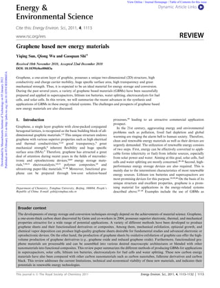
- 7. View Online Fig. 2 (a) Cross-section SEM image of a PANI-NF/graphene composite film, reproduced with permission from ref. 10 ª 2010 American Chemical Society. (b) TEM image of a MnO2 nanoneedle/graphene oxide composite, reproduced with permission from ref. 92 ª 2010 American Chemical Society. Published on 05 February 2011 on http://pubs.rsc.org | doi:10.1039/C0EE00683A (c) TEM image of a Ni(OH)2 nanosheet/graphene composite, reproduced with permission from ref. 118 ª 2010 American Chemical Society. Downloaded by Massachusetts Institute of Technology on 03 January 2012 3.1.2.2 Metal compound/graphene composites. Among metal carbons129,130 have been explored for this purpose. The diffusion compounds, MnO2 is promising for pseudo-capacitors because distances of lithium ions in the nanostructured carbons are short, of the rapid redox reaction at its particle surfaces, low-cost, leading to improved rate performances.23 Apart from carbon stable, and environmental friendliness. A MnO2 nanoneedle/ nanomaterials, silicon, metals and oxides were also studied for graphene oxide composite has been successfully prepared.92 replacing graphite as the anode materials of LIBs. The Cs’s of Although the composite has a uniform morphology (Fig. 2b), its these materials are much higher than that of graphite. However, Cm is moderate and its rate performance is unsatisfactory. The one of the main drawbacks of these materials is their huge loss of Cm at a high discharging rate was attributed to the volume variations during the processes of lithium insertion/ decrease of available pores of the composite because of its low extraction.46,47,131 The volume changes of the electrodes can cause conductivity. In comparison, as conductive graphene-based the pulverization of the whole electrode. Another problem is that nanosheets were used as the starting material, the resulting most metal oxides have poor electrical conductivities. Thus, the composite exhibited high Cm, good rate performance and long blending of carbon nanomaterials into these inorganic materials cycling life.95 is considered to be the most efficient method to overcome both Dai and co-workers reported the in situ growth of single- problems described above.47 On the basis of these considerations, crystalline Ni(OH)2 nanoplates on graphene sheets (Fig. 2c).118 graphene and its composites should have a great potential as the As a 2D conductive substrate, graphene is a unique component anode materials of LIBs.46 for preparing its composites with 2D Ni(OH)2 nanoplates. The synergistic effect of both components rendered the composites 3.2.1 Graphene anodes. Compared with graphite, graphene with an extraordinary high Cm of 935 F gÀ1. Similarly, has a huge SSA of 2600 m2 gÀ1, and more edge sites for anchoring a Co(OH)2/graphene composite was prepared and exhibited other electroactive materials.132,133 Thus, it possesses a much a even higher Cm.120 larger theoretical Cs, and this assumption has been confirmed by different experiments.11,75,133–136 The Li storage of graphene nanosheets was first investigated by Kudo and co-workers.11 The 3.2 Lithium ion batteries Cs of the graphene sheets prepared by the reduction of graphene Lithium ion battery (LIB) is considered to be one of the most oxide was found to be 540 mA h gÀ1, which is much larger than useful batteries in portable electronics due to its high voltage, that of graphite. Furthermore, when carbon nanotubes or high energy density, long cycling life and good environment fullerene were incorporated into graphene, the Cs of the corre- compatibility.23,26 However, with the development of electronic sponding composite increased to 730 or 784 mA h gÀ1 as shown devices, especially in electric vehicles, there are continuous in Fig. 3. It was found that the Cs s of these composites increased demands for batteries with higher power and energy densities, with the contents of their interlayer spacing species. Thus, the and longer cycling life. On the other hand, LIB is recognized as researchers believed that the mechanism of Li storage in gra- a rock-chair battery with Li+ insertion/excitation in the two phene was different from that in graphite. Park et al. think that electrodes during the charging/discharging processes.26 Thus, the lithium can be adsorbed on both sides of a single graphene performance of a LIB strongly depends on the structures and nanosheet with a theoretical Cs of 744 mA h gÀ1 by the formation properties of its electrodes. Graphite is the commercialized anode of Li2C6, similar to that of hard carbons.136 However, the Cs of because of its good life cycle performance and high coulombic tiny graphene sheets with diameters around 0.7 nm was calcu- efficiency.26,124 However the specific capacity (Cs) of graphite is lated to be 1488 mA h gÀ1 by forming Li4C6.137 Kostecki et al. limited to 372 mA h gÀ1 by forming an intercalation compound indicated that the interaction of lithium with few-layers graphene of LiC6. resembled that of bulk graphite, which seems to be different in In order to improve the performance of LIBs, anode materials the case of single-layer graphene.138 The edge effect on the with specific capacities (Cs’s) higher than that of graphite are characteristics of Li diffusion in graphene was theoretically required. A variety of carbon nanomaterials such as carbon investigated by Uthaisar et al. using the density functional nanofibers,125,126 carbon nanotubes127,128 and mesoporous theory.139 It was clearly demonstrated that narrower graphene This journal is ª The Royal Society of Chemistry 2011 Energy Environ. Sci., 2011, 4, 1113–1132 | 1119
- 8. View Online prepared from the rapid thermal expansion of graphite oxide in nitrogen atmosphere were reported to have a Cs of 1264 mA h gÀ1 at the first cycle and it decreased to 848 mA h gÀ1 after 40 cycles.136 Considering the flexible, self-supporting and electrically conductive properties of graphene films, they have potential applications in flexible energy storage devices. The lithium storage in graphene films was firstly investigated by Wallace and co-workers.140 The discharge Cs of a graphene film was measured to be 680 mA h gÀ1 during the first discharge process and it decreased to only 84 mA h gÀ1 at the second cycle. Nguyen et al. discussed the rate performance of the graphene film. The Cs of the graphene film was increased from 84 to 214 mA h gÀ1 as the Published on 05 February 2011 on http://pubs.rsc.org | doi:10.1039/C0EE00683A discharge current density decreased from 50 to 10 mA gÀ1. It is Downloaded by Massachusetts Institute of Technology on 03 January 2012 suggested that the layered structure of graphene film might create barriers to Li ion diffusion.141 Song et al. prepared hollow gra- phene oxide spheres (HGOS) via a water-in-oil (W/O) emulsion technique without the assistance of a surfactant (Fig. 4). After thermal reduction, the resulting hollow graphene spheres exhibited a high Cs of 485 mA h gÀ1 and an improved rate performance because of its hollow structure and porous thin graphene shells. 75 Although the Cs’s graphene anodes are much larger than that of graphite, there are several issues which need to be addressed for their practical applications.132 One of the disadvantages of these anodes is their high irreversible capacities in the first cycles. This is mainly due to the irreversible reaction between lithium and the functional groups of graphene sheets and the formation of a solid electrolyte interface (SEI). These problems can be partly solved by surface modification of graphene sheets.135,142 Fig. 3 (A) Charge/discharge profiles and (B) charge/discharge cycle performances of (a) graphite, (b) graphene, (c) graphene + CNT, and (d) Another problem is the poor rate performances of graphene graphene + C60 at a current density of 0.05 A gÀ1, reproduced with anodes.136 However, the most serious problem of graphene permission from ref. 11 ª 2008 American Chemical Society. anodes is that their galvanostatic discharge curves do not give potential plateaus. This phenomenon indicates the LIBs with graphene anodes cannot provide stable potential outputs, which nanosheets should possess faster discharge performance, mainly will hold back its practical applications. due to their decreased energy barriers and diffusion lengths. Jiao and co-workers studied the lithium storage in highly disordered 3.2.2 Graphene composites as anode materials. Many metals graphene nanosheets. They concluded that the greatly enhanced and their oxides are also promising anode materials of LIBs Cs of graphene is mainly ascribed to its additional reversible because of their huge theoretical lithium ion storage capac- storage sites such as edges and other defects.133 On the basis of ities.46,47,143–145 Blending these materials with graphene to form the facts described above, the mechanism of lithium storage in composites can improve their performance. Examples are the graphene is still an ongoing debate. The Li interaction/extraction composites of graphene and metal or oxide nanoparticles. processes in graphene materials need to be further clarified in the Several metals such as Sn and Sb can be used as the anodes of future. LIBs, because they can reversibly form alloys with lithium. For Graphene powders produced by different methods have been example, the reaction between lithium and Sn can be described as widely explored for the applications as anode materials of follows: LIBs.11,136 Kudo et al. prepared a LIB anode from few-layers graphene nanosheets (10$20 layers) by the chemical reduction of 4.4Li+ + Sn + 4.4eÀ 4 Li4.4Sn graphite oxide, and a Cs of 540 mA h gÀ1 was obtained.11 An improved reversible Cs of 650 mA h gÀ1 was achieved by using the chemically synthesized graphene sheets (2$3 layers) due to their The theoretical reversible Cs of Sn is about 994 mA h gÀ1, loose agglomeration and less-layers stacking.136 After a long- which is much larger than that of graphite (372 mA h gÀ1).144 term cycling over 100 cycles, its Cs decreased to 460 mA h gÀ1. However, Sn nanoparticles tend to aggregate during the cycling Compared to the graphene prepared by chemical reduction, process, causing a rapid decrease of its capacity. This problem thermal exfoliated graphene has a higher Cs. The graphene made can be partially resolved by depositing Sn nanoparticles on from graphite by oxidation, rapid expansion and ultrasonic graphene sheets to form a 3D nanostructure.144 The resulting treatment was tested to have an initial Cs as high as 1233 mA h graphene/Sn composite showed a discharge Cs of 1250 mA h gÀ1 gÀ1 and a reversible Cs of 672 mA h gÀ1.135 Graphene nanosheets in the first cycle, 810 mA h gÀ1 in the second cycle and 508 mA h 1120 | Energy Environ. Sci., 2011, 4, 1113–1132 This journal is ª The Royal Society of Chemistry 2011