SlideShare una empresa de Scribd logo
1 de 29
Descargar para leer sin conexión
Chapter 3

                     RADIATION DOSIMETERS


     J. IZEWSKA
     Division of Human Health,
     International Atomic Energy Agency,
     Vienna

     G. RAJAN
     Medical Physics and Safety Section,
     Bhabha Atomic Research Centre,
     Mumbai, Maharashtra, India


3.1. INTRODUCTION

      A radiation dosimeter is a device, instrument or system that measures or
evaluates, either directly or indirectly, the quantities exposure, kerma,
absorbed dose or equivalent dose, or their time derivatives (rates), or related
quantities of ionizing radiation. A dosimeter along with its reader is referred to
as a dosimetry system.
      Measurement of a dosimetric quantity is the process of finding the value
of the quantity experimentally using dosimetry systems. The result of a
measurement is the value of a dosimetric quantity expressed as the product of
a numerical value and an appropriate unit.
      To function as a radiation dosimeter, the dosimeter must possess at least
one physical property that is a function of the measured dosimetric quantity
and that can be used for radiation dosimetry with proper calibration. In order
to be useful, radiation dosimeters must exhibit several desirable characteristics.
For example, in radiotherapy exact knowledge of both the absorbed dose to
water at a specified point and its spatial distribution are of importance, as well
as the possibility of deriving the dose to an organ of interest in the patient. In
this context, the desirable dosimeter properties will be characterized by
accuracy and precision, linearity, dose or dose rate dependence, energy
response, directional dependence and spatial resolution.
      Obviously, not all dosimeters can satisfy all characteristics. The choice of
a radiation dosimeter and its reader must therefore be made judiciously, taking
into account the requirements of the measurement situation; for example, in
radiotherapy ionization chambers are recommended for beam calibrations


                                                                               71
CHAPTER 3


(reference dosimetry: see Chapter 9) and other dosimeters, such as those
discussed below, are suitable for the evaluation of the dose distribution
(relative dosimetry) or dose verification.


3.2. PROPERTIES OF DOSIMETERS

3.2.1.   Accuracy and precision

      In radiotherapy dosimetry the uncertainty associated with the
measurement is often expressed in terms of accuracy and precision. The
precision of dosimetry measurements specifies the reproducibility of the
measurements under similar conditions and can be estimated from the data
obtained in repeated measurements. High precision is associated with a small
standard deviation of the distribution of the measurement results. The accuracy
of dosimetry measurements is the proximity of their expectation value to the
‘true value’ of the measured quantity. Results of measurements cannot be
absolutely accurate and the inaccuracy of a measurement result is charac-
terized as ‘uncertainty’.
      The uncertainty is a parameter that describes the dispersion of the
measured values of a quantity; it is evaluated by statistical methods (type A) or
by other methods (type B), has no known sign and is usually assumed to be
symmetrical.
      The error of measurement is the difference between the measured value
of a quantity and the true value of that quantity.

     ● An error has both a numerical value and a sign.
     ● Typically, the measurement errors are not known exactly, but they are
       estimated in the best possible way, and, where possible, compensating
       corrections are introduced.
     ● After application of all known corrections, the expectation value for
       errors should be zero and the only quantities of concern are the uncer-
       tainties.

3.2.1.1. Type A standard uncertainties

      If a measurement of a dosimetric quantity x is repeated N times, then the
best estimate for x is x, the arithmetic mean value of all measurements xi:


72
RADIATION DOSIMETERS


              N

              Âx
          1
       x=             i                                                        (3.1)
          N   i =1


      The standard deviation sx characterizes the average uncertainty for an
individual result xi and is given by:

                          N

                          Â
               1
       sx =             (x - x) 2                                              (3.2)
              N - 1 i =1 i

       The standard deviation of the mean value is given by:

                                           N

                                           Â (x
              1                    1
       sx =          sx =                             - x)2                    (3.3)
              N               N ( N - 1)   i =1
                                                  i


   ● The standard uncertainty of type A, denoted uA, is defined as the
     standard deviation of the mean value, uA = s x .
   ● The standard uncertainty of type A is obtained by a statistical analysis of
     repeated measurements and, in principle, can be reduced by increasing
     the number of measurements.

3.2.1.2. Type B standard uncertainties

      Type B standard uncertainties uB cannot be estimated by repeated
measurements; rather, they are intelligent guesses or scientific judgements of
non-statistical uncertainties associated with the measurement. They include
influences on the measuring process, application of correction factors or
physical data taken from the literature.
      It is often assumed that type B standard uncertainties have a probability
distribution, such as a normal (Gaussian) or a rectangular distribution (equal
probability anywhere within the given limits). Type B standard uncertainties
can be derived by estimating the limit beyond which the value of the factor is
not going to lie, and a fraction of this limit is taken as uB. The fraction is chosen
according to the distribution assumed.

3.2.1.3. Combined and expanded uncertainties

      The equation that determines a dosimetric quantity Q at a point P is of
the type:


                                                                                  73
CHAPTER 3


                 N
         Q P = M P Fi                                                       (3.4)
                 i =1


where M is the reading provided by the dosimetry system and Fi is the
correction or conversion coefficient.

     ●   The combined standard uncertainty uC associated with the quantity Q is a
         quadratic summation of type A (uA) and type B (uB) uncertainties:

         uC = u A + u B
                2     2                                                     (3.5)

     ● The combined uncertainty is assumed to exhibit a normal distribution and
       is multiplied by a coverage factor, denoted by k, to obtain the expanded
       uncertainty U = kuC. The result of the measurement of the quantity Q is
       then expressed by QP ± U.
     ● The expanded uncertainty U with the coverage factor k = 2, corre-
       sponding to the 95% confidence level, is often used to represent the
       overall uncertainty, which relates to the accuracy of the measurement of
       the quantity Q.

3.2.2.     Linearity

      Ideally, the dosimeter reading M should be linearly proportional to the
dosimetric quantity Q. However, beyond a certain dose range a non-linearity
sets in. The linearity range and the non-linearity behaviour depend on the type
of dosimeter and its physical characteristics.
      Two typical examples of response characteristics of dosimetry systems are
shown in Fig. 3.1. Curve A first exhibits linearity with dose, then a supralinear
behaviour, and finally saturation. Curve B first exhibits linearity and then
saturation at high doses.
      In general, a non-linear behaviour should be corrected for. A dosimeter
and its reader may both exhibit non-linear characteristics, but their combined
effect could produce linearity over a wider range.

3.2.3.     Dose rate dependence

     Integrating systems measure the integrated response of a dosimetry
system. For such systems the measured dosimetric quantity should be
independent of the rate of that quantity.


74
RADIATION DOSIMETERS


                                                                 A
         Dosimeter reading


                                                                         B


                                        Dose

FIG. 3.1. Response characteristics of two dosimetry systems. Curve A first exhibits
linearity with dose, then supralinear behaviour and finally saturation. Curve B first
exhibits linearity and then saturation at high doses.


      Ideally, the response of a dosimetry system M/Q at two different dose
rates ((dQ/dt)1 and (dQ/dt)2) should remain constant. In reality, the dose rate
may influence the dosimeter readings and appropriate corrections are
necessary, for example recombination corrections for ionization chambers in
pulsed beams.

3.2.4.   Energy dependence

      The response of a dosimetry system M/Q is generally a function of
radiation beam quality (energy). Since the dosimetry systems are calibrated at
a specified radiation beam quality (or qualities) and used over a much wider
energy range, the variation of the response of a dosimetry system with
radiation quality (called energy dependence) requires correction.
      Ideally, the energy response should be flat (i.e. the system calibration
should be independent of energy over a certain range of radiation qualities). In
reality, the energy correction has to be included in the determination of the
quantity Q for most measurement situations. Ιn radiotherapy, the quantity of
interest is the dose to water (or to tissue). As no dosimeter is water or tissue
equivalent for all radiation beam qualities, the energy dependence is an
important characteristic of a dosimetry system.


                                                                                  75
CHAPTER 3


3.2.5.   Directional dependence

      The variation in response of a dosimeter with the angle of incidence of
radiation is known as the directional, or angular, dependence of the dosimeter.
Dosimeters usually exhibit directional dependence, due to their constructional
details, physical size and the energy of the incident radiation. Directional
dependence is important in certain applications, for example in in vivo
dosimetry while using semiconductor dosimeters. Therapy dosimeters are
generally used in the same geometry as that in which they are calibrated.

3.2.6.   Spatial resolution and physical size

      Since the dose is a point quantity, the dosimeter should allow the determi-
nation of the dose from a very small volume (i.e. one needs a ‘point dosimeter’
to characterize the dose at a point). Τhe position of the point where the dose is
determined (i.e. its spatial location) should be well defined in a reference
coordinate system.
      Thermoluminescent dosimeters (TLDs) come in very small dimensions
and their use, to a great extent, approximates a point measurement. Film
dosimeters have excellent 2-D and gels 3-D resolution, where the point
measurement is limited only by the resolution of the evaluation system.
Ionization chamber type dosimeters, however, are of finite size to give the
required sensitivity, although the new type of pinpoint microchambers partially
overcomes the problem.

3.2.7.   Readout convenience

     Direct reading dosimeters (e.g. ionization chambers) are generally more
convenient than passive dosimeters (i.e. those that are read after due
processing following the exposure, for example TLDs and films). While some
dosimeters are inherently of the integrating type (e.g. TLDs and gels), others
can measure in both integral and differential modes (ionization chambers).

3.2.8.   Convenience of use

      Ionization chambers are reusable, with no or little change in sensitivity
within their lifespan. Semiconductor dosimeters are reusable, but with a
gradual loss of sensitivity within their lifespan; however, some dosimeters are
not reusable (e.g. films, gels and alanine). Some dosimeters measure dose
distribution in a single exposure (e.g. films and gels) and some dosimeters are


76
RADIATION DOSIMETERS


quite rugged (i.e. handling will not influence sensitivity, for example ionization
chambers), while others are sensitive to handling (e.g. TLDs).


3.3. IONIZATION CHAMBER DOSIMETRY SYSTEMS

3.3.1.   Chambers and electrometers

      Ionization chambers are used in radiotherapy and in diagnostic radiology
for the determination of radiation dose. The dose determination in reference
irradiation conditions is also called beam calibration (see Chapter 9 for
details). Ionization chambers come in various shapes and sizes, depending upon
the specific requirements, but generally they all have the following properties:

    ● An ionization chamber is basically a gas filled cavity surrounded by a
      conductive outer wall and having a central collecting electrode (see
      Fig. 3.2). The wall and the collecting electrode are separated with a high
      quality insulator to reduce the leakage current when a polarizing voltage
      is applied to the chamber.
    ● A guard electrode is usually provided in the chamber to further reduce
      chamber leakage. The guard electrode intercepts the leakage current and
      allows it to flow to ground, bypassing the collecting electrode. It also
      ensures improved field uniformity in the active or sensitive volume of the
      chamber, with resulting advantages in charge collection.
    ● Measurements with open air ionization chambers require temperature
      and pressure correction to account for the change in the mass of air in the
      chamber volume, which changes with the ambient temperature and
      pressure.


                                         Graphite      Central electrode
   PTCFE                                                              Outer electrode
                        Insulator


                                                                Aluminium


                Dural


         FIG. 3.2. Basic design of a cylindrical Farmer type ionization chamber.


                                                                                        77
CHAPTER 3


Electrometers are devices for measuring small currents, of the order of 10–9 A
or less. An electrometer used in conjunction with an ionization chamber is a
high gain, negative feedback, operational amplifier with a standard resistor or a
standard capacitor in the feedback path to measure the chamber current or
charge collected over a fixed time interval, as shown schematically in Fig. 3.3.

3.3.2.   Cylindrical (thimble type) ionization chambers

      The most popular cylindrical ionization chamber is the 0.6 cm3 chamber
designed by Farmer and originally manufactured by Baldwin, but now available
from several vendors, for beam calibration in radiotherapy dosimetry. Its
chamber sensitive volume resembles a thimble, and hence the Farmer type
chamber is also known as a thimble chamber. A schematic diagram of a Farmer
type thimble ionization chamber is shown in Fig. 3.2; ionization chamber based
dosimetry systems are discussed in Section 9.2.
      Cylindrical chambers are produced by various manufacturers, with active
volumes between 0.1 and 1 cm3. They typically have an internal length no
greater than 25 mm and an internal diameter no greater than 7 mm. The wall
material is of low atomic number Z (i.e. tissue or air equivalent), with the
thickness less than 0.1 g/cm2. A chamber is equipped with a buildup cap with a
thickness of about 0.5 g/cm2 for calibration free in air using 60Co radiation.
      The chamber construction should be as homogeneous as possible,
although an aluminium central electrode of about 1 mm in diameter is typically


                                           Cf


                                         Rf
                                                -


                                                +
                         I                                     V = II Rf (rate mode)


         Rf = feedback resistor                                V = (II – t)/Cf
              (variable to vary sensitivity)                   (integrated mode)

         Cf = feedback capacitor
              (variable to vary sensitivity)

                  FIG. 3.3. Electrometer in feedback mode of operation.


78
RADIATION DOSIMETERS


used to ensure flat energy dependence. Construction details of various
commercially available cylindrical chambers are given in the IAEA Technical
Reports Series (TRS) 277 and TRS 398 codes of practice. The use of the
cylindrical chamber in electron and photon beam dosimetry is discussed in
Chapter 9.

3.3.3.   Parallel-plate (plane-parallel) ionization chambers

      A parallel-plate ionization chamber consists of two plane walls, one
serving as an entry window and polarizing electrode and the other as the back
wall and collecting electrode, as well as a guard ring system. The back wall is
usually a block of conducting plastic or a non-conducting material (usually
Perspex or polystyrene) with a thin conducting layer of graphite forming the
collecting electrode and the guard ring system on top. A schematic diagram of
a parallel-plate ionization chamber is shown in Fig. 3.4.
      The parallel-plate chamber is recommended for dosimetry of electron
beams with energies below 10 MeV. It is also used for surface dose and depth
dose measurements in the buildup region of megavoltage photon beams. Dose
measurements in the buildup region of photon beams are discussed in
Section 6.13. The characteristics of commercially available parallel-plate
chambers and the use of these chambers in electron beam dosimetry are
explained in detail in the TRS 381 and TRS 398 codes of practice. Some
parallel-plate chambers require significant fluence perturbation correction
because they are provided with an inadequate guard width.

3.3.4.   Brachytherapy chambers

      Sources used in brachytherapy are low air kerma rate sources that require
chambers of sufficient volume (about 250 cm3 or more) for adequate sensitivity.
Well type chambers or re-entrant chambers are ideally suited for calibration
and standardization of brachytherapy sources. Figure 3.5 shows a schematic
diagram of a well type chamber.
      Well type chambers should be designed to accommodate sources of the
typical sizes and shapes that are in clinical use in brachytherapy and are usually
calibrated in terms of the reference air kerma rate.

3.3.5.   Extrapolation chambers

      Extrapolation chambers are parallel-plate chambers with a variable
sensitive volume. They are used in the measurement of surface doses in ortho-


                                                                               79
CHAPTER 3


            a


                                                              Schnitt A–B
                3          1       2         3

                               d
                               m
                      g


        A                                                                      B


FIG. 3.4. Parallel-plate ionization chamber. 1: the polarizing electrode. 2: the measuring
electrode. 3: the guard ring. a: the height (electrode separation) of the air cavity. d: the
diameter of the polarizing electrode. m: the diameter of the collecting electrode. g: the
width of the guard ring.


voltage and megavoltage X ray beams and in the dosimetry of b rays, and low
energy X rays. They can also be used in absolute radiation dosimetry when
directly embedded into a tissue equivalent phantom. The cavity perturbation
for electrons can be eliminated by making measurements as a function of the
cavity thickness and then extrapolating to zero thickness. Using this chamber,
the cavity perturbation for parallel-plate chambers of finite thickness can be
estimated.


80
RADIATION DOSIMETERS


                                               Source holder

                                                     Collecting electrode
                                               Outer electrode (HV)

                                               Insulator


                                                To electrometer


             FIG. 3.5. Basic design of a brachytherapy well type chamber.


3.4. FILM DOSIMETRY

3.4.1.   Radiographic film

      Radiographic X ray film performs several important functions in
diagnostic radiology, radiotherapy and radiation protection. It can serve as a
radiation detector, a relative dosimeter, a display device and an archival
medium.
      Unexposed X ray film consists of a base of thin plastic with a radiation
sensitive emulsion (silver bromide (AgBr) grains suspended in gelatin) coated
uniformly on one or both sides of the base.

    ● Ionization of AgBr grains, as a result of radiation interaction, forms a
      latent image in the film. This image only becomes visible (film
      blackening) and permanent subsequently to processing.
    ● Light transmission is a function of the film opacity and can be measured
      in terms of optical density (OD) with devices called densitometers.
    ● The OD is defined as OD = log10 (I0/I) and is a function of dose. I0 is the
      initial light intensity and I is the intensity transmitted through the film.
    ● Film gives excellent 2-D spatial resolution and, in a single exposure,
      provides information about the spatial distribution of radiation in the
      area of interest or the attenuation of radiation by intervening objects.


                                                                               81
CHAPTER 3


     ● Τhe useful dose range of film is limited and the energy dependence is
       pronounced for lower energy photons. The response of the film depends
       on several parameters, which are difficult to control. Consistent
       processing of the film is a particular challenge in this regard.
     ● Typically, film is used for qualitative dosimetry, but with proper
       calibration, careful use and analysis film can also be used for dose
       evaluation.
     ● Various types of film are available for radiotherapy work (e.g. direct
       exposure non-screen films for field size verification, phosphor screen
       films used with simulators and metallic screen films used in portal
       imaging).
     ● Unexposed film would exhibit a background OD called the fog density
       (ODf). The density due to radiation exposure, called the net OD, can be
       obtained from the measured density by subtracting the fog density.
     ● OD readers include film densitometers, laser densitometers and
       automatic film scanners. The principle of operation of a simple film densi-
       tometer is shown in Fig. 3.6.

       Ideally, the relationship between the dose and OD should be linear, but
this is not always the case. Some emulsions are linear, some are linear over a
limited dose range and others are non-linear. The dose versus OD curve,
known as the sensitometric curve (also known as the characteristic or H&D
curve, in honour of Hurter and Driffield, who first investigated the
relationship) must therefore be established for each film before using it for
dosimetry work.
       A typical H&D curve for a radiographic film is shown in Fig. 3.7. It has
four regions: (1) fog, at low or zero exposures; (2) toe; (3) a linear portion at


                                      Log ratio amplifier

                Isig       _
                                                                           2.99


     Film        I0        +                                   (3½ digits DPM)
                                                               OD = log10 (I0/Isig)


                          FIG. 3.6. Basic film densitometer.


82
RADIATION DOSIMETERS


intermediate exposures; and (4) shoulder and saturation at high exposures. The
linear portion is referred to as optimum measurement conditions, the toe is the
region of underexposure and the shoulder is the region of overexposure.
      Important parameters of film response to radiation are gamma, latitude
and speed:

   ● The slope of the straight line portion of the H&D curve is called the
     gamma of the film.
   ● The exposure should be chosen to make all parts of the radiograph lie on
     the linear portion of the H&D curve, to ensure the same contrast for all
     ODs.
   ● The latitude is defined as the range of exposures over which the ODs will
     lie in the linear region.
   ● The speed of a film is determined by giving the exposure required to
     produce an OD of 1.0 greater than the OD of fog.

     Typical applications of a radiographic film in radiotherapy are qualitative
and quantitative measurements, including electron beam dosimetry, quality
control of radiotherapy machines (e.g. congruence of light and radiation fields
and the determination of the position of a collimator axis, the so called star


            4                                               (4) Shoulder


            3
       OD


                                               (3) Linear portion

            2


            1
                (1) Fog              (2) Toe


            0
                1              10              100                  1000
                               Exposure (arbitrary units)

  FIG. 3.7. Typical sensitometric (characteristic H&D) curve for a radiographic film.


                                                                                        83
CHAPTER 3


test), verification of treatment techniques in various phantoms and portal
imaging.

3.4.2.    Radiochromic film

       Radiochromic film is a new type of film in radiotherapy dosimetry. The
most commonly used is a GafChromic film. It is a colourless film with a nearly
tissue equivalent composition (9.0% hydrogen, 60.6% carbon, 11.2% nitrogen
and 19.2% oxygen) that develops a blue colour upon radiation exposure.
       Radiochromic film contains a special dye that is polymerized upon
exposure to radiation. The polymer absorbs light, and the transmission of light
through the film can be measured with a suitable densitometer. Radiochromic
film is self-developing, requiring neither developer nor fixer. Since radio-
chromic film is grainless, it has a very high resolution and can be used in high
dose gradient regions for dosimetry (e.g. measurements of dose distributions in
stereotactic fields and in the vicinity of brachytherapy sources).
       Dosimetry with radiochromic films has a few advantages over radio-
graphic films, such as ease of use; elimination of the need for darkroom
facilities, film cassettes or film processing; dose rate independence; better
energy characteristics (except for low energy X rays of 25 kV or less); and
insensitivity to ambient conditions (although excessive humidity should be
avoided). Radiochromic films are generally less sensitive than radiographic
films and are useful at higher doses, although the dose response non-linearity
should be corrected for in the upper dose region.

     ● Radiochromic film is a relative dosimeter. If proper care is taken with
       calibration and the environmental conditions, a precision better than 3%
       is achievable.
     ● Data on the various characteristics of radiochromic films (e.g. sensitivity,
       linearity, uniformity, reproducibility and post-irradiation stability) are
       available in the literature.


3.5. LUMINESCENCE DOSIMETRY

      Some materials, upon absorption of radiation, retain part of the absorbed
energy in metastable states. When this energy is subsequently released in the
form of ultraviolet, visible or infrared light, the phenomenon is called lumines-
cence. Two types of luminescence, fluorescence and phosphorescence, are
known, which depend on the time delay between stimulation and the emission
of light. Fluorescence occurs with a time delay of between 10–10 and 10–8 s;


84
RADIATION DOSIMETERS


phosphorescence occurs with a time delay exceeding 10–8 s. The process of
phosphorescence can be accelerated with a suitable excitation in the form of
heat or light.

    ● If the exciting agent is heat, the phenomenon is known as thermolumines-
      cence and the material is called a thermoluminescent material, or a TLD
      when used for purposes of dosimetry.
    ● If the exciting agent is light, the phenomenon is referred to as optically
      stimulated luminescence (OSL).

      As discussed in Section 1.4, the highly energetic secondary charged
particles, usually electrons, that are produced in the primary interactions of
photons with matter are mainly responsible for the photon energy deposition in
matter. In a crystalline solid these secondary charged particles release
numerous low energy free electrons and holes through ionizations of atoms and
ions. The free electrons and holes thus produced will either recombine or
become trapped in an electron or hole trap, respectively, somewhere in the
crystal.
      The traps can be intrinsic or can be introduced in the crystal in the form of
lattice imperfections consisting of vacancies or impurities. Two types of trap are
known in general: storage traps and recombination centres.

    ● A storage trap merely traps free charge carriers and releases them during
      the subsequent (a) heating, resulting in the thermoluminescence process,
      or (b) irradiation with light, resulting in the OSL process.
    ● A charge carrier released from a storage trap may recombine with a
      trapped charge carrier of opposite sign in a recombination centre
      (luminescence centre). The recombination energy is at least partially
      emitted in the form of ultraviolet, visible or infrared light that can be
      measured with photodiodes or photomultiplier tubes (PMTs).

3.5.1.   Thermoluminescence

      Thermoluminescence is thermally activated phosphorescence; it is the
most spectacular and widely known of a number of different ionizing radiation
induced thermally activated phenomena. Its practical applications range from
archaeological pottery dating to radiation dosimetry. In 1968 Cameron,
Suntharalingam and Kenney published a book on the thermoluminescence
process that is still considered an excellent treatise on the practical aspects of
the thermoluminescence phenomenon. A useful phenomenological model of
the thermoluminescence mechanism is provided in terms of the band model for


                                                                                85
CHAPTER 3


solids. The storage traps and recombination centres, each type characterized
with an activation energy (trap depth) that depends on the crystalline solid and
the nature of the trap, are located in the energy gap between the valence band
and the conduction band. The states just below the conduction band represent
electron traps, the states just above the valence band are hole traps. The
trapping levels are empty before irradiation (i.e. the hole traps contain
electrons and the electron traps do not).
      During irradiation the secondary charged particles lift electrons into the
conduction band either from the valence band (leaving a free hole in the
valence band) or from an empty hole trap (filling the hole trap).
      The system may approach thermal equilibrium through several means:

     ● Free charge carriers recombine with the recombination energy converted
       into heat;
     ● A free charge carrier recombines with a charge carrier of opposite sign
       trapped at a luminescence centre, the recombination energy being
       emitted as optical fluorescence;
     ● The free charge carrier becomes trapped at a storage trap, and this event
       is then responsible for phosphorescence or the thermoluminescence and
       OSL processes.

3.5.2.   Thermoluminescent dosimeter systems

     The TLDs most commonly used in medical applications are LiF:Mg,Ti,
LiF:Mg,Cu,P and Li2B4O7:Mn, because of their tissue equivalence. Other
TLDs, used because of their high sensitivity, are CaSO4:Dy, Al2O3:C and
CaF2:Mn.

     ● TLDs are available in various forms (e.g. powder, chips, rods and
       ribbons).
     ● Before they are used, TLDs need to be annealed to erase the residual
       signal. Well established and reproducible annealing cycles, including the
       heating and cooling rates, should be used.

       A basic TLD reader system consists of a planchet for placing and heating
the TLD, a PMT to detect the thermoluminescence light emission and convert
it into an electrical signal linearly proportional to the detected photon fluence
and an electrometer for recording the PMT signal as a charge or current. A
basic schematic diagram of a TLD reader is shown in Fig. 3.8.


86
RADIATION DOSIMETERS


                                              Electrometer
    HV
                                              Thermoluminescence ~ charge

    PMT


    TLD

                  Heater

                            FIG. 3.8. TLD reader.


● The thermoluminescence intensity emission is a function of the TLD
  temperature T. Keeping the heating rate constant makes the temperature
  T proportional to time t, and so the thermoluminescence intensity can be
  plotted as a function of t if a recorder output is available with the TLD
  measuring system. The resulting curve is called the TLD glow curve. In
  general, if the emitted light is plotted against the crystal temperature one
  obtains a thermoluminescence thermogram (Fig. 3.9).
● The peaks in the glow curve may be correlated with trap depths
  responsible for thermoluminescence emission.
● The main dosimetric peak of the LiF:Mg,Ti glow curve between 180ºC
  and 260ºC is used for dosimetry. The peak temperature is high enough so
  as not to be affected by room temperature and still low enough so as not
  to interfere with black body emission from the heating planchet.
● The total thermoluminescence signal emitted (i.e. the area under the
  appropriate portion of the glow curve) can be correlated to dose through
  proper calibration.
● Good reproducibility of heating cycles during the readout is important for
  accurate dosimetry.
● The thermoluminescence signal decreases in time after the irradiation
  due to spontaneous emission of light at room temperature. This process is
  called fading. Typically, for LiF:Mg,Ti, the fading of the dosimetric peak
  does not exceed a few per cent in the months after irradiation.
● The thermoluminescence dose response is linear over a wide range of
  doses used in radiotherapy, although it increases in the higher dose
  region, exhibiting supralinear behaviour before it saturates at even higher
  doses.


                                                                            87
CHAPTER 3


                                      1.0         Time after irradiation
 Normalized thermolumescence signal


                                                           1h
                                      0.8                  4d
                                                           20 d


                                      0.6


                                      0.4


                                      0.2


                                      0.0
                                            0         50          100      150         200          250   300   350   400
                                                                                 Temperature (˚C)

FIG. 3.9. A typical thermogram (glow curve) of LiF:Mg,Ti measured with a TLD reader
at a low heating rate.


                                      ● TLDs need to be calibrated before they are used (thus they serve as
                                        relative dosimeters). To derive the absorbed dose from the thermolumi-
                                        nescence reading a few correction factors have to be applied, such as
                                        those for energy, fading and dose response non-linearity.
                                      ● Typical applications of TLDs in radiotherapy are: in vivo dosimetry on
                                        patients (either as a routine quality assurance procedure or for dose
                                        monitoring in special cases, for example complicated geometries, dose to
                                        critical organs, total body irradiation (TBI), brachytherapy); verification
                                        of treatment techniques in various phantoms (e.g. anthropomorphic
                                        phantoms); dosimetry audits (such as the IAEA–World Health Organi-
                                        zation (WHO) TLD postal dose audit programme); and comparisons
                                        among hospitals.

3.5.3.                                          Optically stimulated luminescence systems

     OSL is based on a principle similar to that of thermoluminescence
dosimetry. Instead of heat, light (from a laser) is used to release the trapped
energy in the form of luminescence. OSL is a novel technique offering a


88
RADIATION DOSIMETERS


potential for in vivo dosimetry in radiotherapy. The integrated dose measured
during irradiation can be evaluated using OSL directly afterwards.
      The optical fibre optically stimulated thermoluminescent dosimeter
consists of a small (~1 mm3) chip of carbon doped aluminium oxide (Al2O3:C)
coupled with a long optical fibre, a laser, a beam splitter and a collimator, a
PMT, electronics and software. To produce OSL, the chip is excited with laser
light through an optical fibre, and the resulting luminescence (blue light) is
carried back in the same fibre, reflected through 90º by the beam splitter and
measured in a PMT.
      The optical fibre dosimeter exhibits high sensitivity over the wide range
of dose rates and doses used in radiotherapy. The OSL response is generally
linear and independent of energy as well as the dose rate, although the angular
response requires correction.
      Various experimental set-ups exist, such as pulsed OSL or OSL used in
conjunction with radioluminescence. Radioluminescence is emitted promptly
at the time of dosimeter irradiation and provides information on the dose rate
during irradiation, while OSL provides the integrated dose thereafter. This
technique, although not yet used routinely in radiotherapy, may prove to be a
valuable tool for in vivo dosimetry in the future.


3.6. SEMICONDUCTOR DOSIMETRY

3.6.1.   Silicon diode dosimetry systems

      A silicon diode dosimeter is a p–n junction diode. The diodes are
produced by taking n type or p type silicon and counter-doping the surface to
produce the opposite type material. These diodes are referred to as n–Si or p–
Si dosimeters, depending upon the base material. Both types of diode are
commercially available, but only the p–Si type is suitable for radiotherapy
dosimetry, since it is less affected by radiation damage and has a much smaller
dark current.
      Radiation produces electron–hole (e–h) pairs in the body of the
dosimeter, including the depletion layer. The charges (minority charge carriers)
produced in the body of the dosimeter, within the diffusion length, diffuse into
the depleted region. They are swept across the depletion region under the
action of the electric field due to the intrinsic potential. In this way a current is
generated in the reverse direction in the diode.


                                                                                  89
CHAPTER 3


     ● Diodes are used in the short circuit mode, since this mode exhibits a
       linear relationship between the measured charge and dose. They are
       usually operated without an external bias to reduce leakage current.
     ● Diodes are more sensitive and smaller in size than typical ionization
       chambers. They are relative dosimeters and should not be used for beam
       calibration, since their sensitivity changes with repeated use due to
       radiation damage.
     ● Diodes are particularly useful for measurement in phantoms, for example
       of small fields used in stereotactic radiosurgery or high dose gradient
       areas such as the penumbra region. They are also often used for measure-
       ments of depth doses in electron beams. For use with beam scanning
       devices in water phantoms, they are packaged in a waterproof encapsu-
       lation. When used in electron beam depth dose measurements, diodes
       measure directly the dose distribution (in contrast to the ionization
       measured by ionization chambers).
     ● Diodes are widely used in routine in vivo dosimetry on patients or for
       bladder or rectum dose measurements. Diodes for in vivo dosimetry are
       provided with buildup encapsulation and hence must be appropriately
       chosen, depending on the type and quality of the clinical beams. The
       encapsulation also protects the fragile diode from physical damage.
     ● Diodes need to be calibrated when they are used for in vivo dosimetry,
       and several correction factors have to be applied for dose calculation. The
       sensitivity of diodes depends on their radiation history, and hence the
       calibration has to be repeated periodically.
     ● Diodes show a variation in dose response with temperature (this is partic-
       ularly important for long radiotherapy treatments), dependence of signal
       on the dose rate (care should be taken for different source to skin
       distances), angular (directional) dependence and energy dependence
       even for small variations in the spectral composition of radiation beams
       (important for the measurement of entrance and exit doses).

3.6.2.    MOSFET dosimetry systems

      A metal-oxide semiconductor field effect transistor (MOSFET), a
miniature silicon transistor, possesses excellent spatial resolution and offers
very little attenuation of the beam due to its small size, which is particularly
useful for in vivo dosimetry. MOSFET dosimeters are based on the
measurement of the threshold voltage, which is a linear function of absorbed
dose. Ionizing radiation penetrating the oxide generates charge that is
permanently trapped, thus causing a change in threshold voltage. The
integrated dose may be measured during or after irradiation. MOSFETs


90
RADIATION DOSIMETERS


require a connection to a bias voltage during irradiation. They have a limited
lifespan.

    ● A single MOSFET dosimeter can cover the full energy range of photons
      and electrons, although the energy response should be examined, since it
      varies with radiation quality. For megavoltage beams, however,
      MOSFETs do not require energy correction, and a single calibration
      factor can be used.
    ● MOSFETs exhibit small axial anisotropy (±2% for 360º) and do not
      require dose rate corrections.
    ● Similarly to diodes, single MOSFETs exhibit a temperature dependence,
      but this effect has been overcome by specially designed double detector
      MOSFET systems. In general, they show non-linearity of response with
      the total absorbed dose; however, during their specified lifespan,
      MOSFETs retain adequate linearity. MOSFETs are also sensitive to
      changes in the bias voltage during irradiation (it must be stable), and their
      response drifts slightly after the irradiation (the reading must be taken in
      a specified time after exposure).
    ● MOSFETs have been in use for the past few years in a variety of radio-
      therapy applications for in vivo and phantom dose measurements,
      including routine patient dose verification, brachytherapy, TBI, intensity
      modulated radiotherapy (IMRT), intraoperative radiotherapy and radio-
      surgery. They are used with or without additional buildup, depending on
      the application.


3.7. OTHER DOSIMETRY SYSTEMS

3.7.1.      Alanine/electron paramagnetic resonance dosimetry system

      Alanine, one of the amino acids, pressed in the form of rods or pellets
with an inert binding material, is typically used for high dose dosimetry. The
dosimeter can be used at a level of about 10 Gy or more with sufficient
precision for radiotherapy dosimetry. The radiation interaction results in the
formation of alanine radicals, the concentration of which can be measured
using an electron paramagnetic resonance (known also as electron spin
resonance) spectrometer. The intensity is measured as the peak to peak height
of the central line in the spectrum. The readout is non-destructive.

    ●    Alanine is tissue equivalent and requires no energy correction within the
         quality range of typical therapeutic beams. It exhibits very little fading for


                                                                                    91
CHAPTER 3


       many months after irradiation. The response depends on environmental
       conditions during irradiation (temperature) and storage (humidity).
     ● At present, alanine’s potential application for radiotherapy is in
       dosimetry comparisons among hospitals.

3.7.2.   Plastic scintillator dosimetry system

      Plastic scintillators are a relatively new development in radiotherapy
dosimetry. The light generated in the scintillator during its irradiation is carried
away by an optical fibre to a PMT located outside the irradiation room. A
typical set-up requires two sets of optical fibres, which are coupled to two
different PMTs, allowing subtraction of the background Cerenkov radiation
from the measured signal. The response of the scintillation dosimeter is linear
in the dose range of therapeutic interest.
      Plastic scintillators are almost water equivalent in terms of electron
density and atomic composition. Typically, they match the water mass stopping
power and mass energy absorption coefficient to within ±2% for the range of
beam energies in clinical use, including the kilovoltage region. Scintillators are
nearly energy independent and can thus be used directly for relative dose
measurements.

     ● Plastic scintillation dosimeters can be made very small (about 1 mm3 or
       less) and yet give adequate sensitivity for clinical dosimetry. Hence they
       can be used in cases where high spatial resolution is required (e.g. high
       dose gradient regions, buildup regions, interface regions, small field
       dosimetry and doses very close to brachytherapy sources). Due to flat
       energy dependence and small size, plastic scintillators are ideal
       dosimeters for brachytherapy applications.
     ● Dosimetry based on plastic scintillators is characterized by good repro-
       ducibility and long term stability. Scintillators suffer no significant
       radiation damage (up to about 10 kGy), although the light yield should be
       monitored when used clinically.
     ● Plastic scintillators are independent of dose rate and can be used from
       10 mGy/min (ophthalmic plaque dosimetry) to about 10 Gy/min (external
       beam dosimetry). They have no significant directional dependence and
       need no ambient temperature or pressure corrections.

3.7.3.   Diamond dosimeters

     Diamonds change their resistance upon radiation exposure. When
applying a bias voltage, the resulting current is proportional to the dose rate of


92
RADIATION DOSIMETERS


radiation. Commercially available diamond dosimeters are designed to
measure relative dose distributions in high energy photon and electron beams.
The dosimeter is based on a natural diamond crystal sealed in a polystyrene
housing with a bias applied through thin golden contacts.

    ● Diamonds have a small sensitive volume, of the order of a few cubic milli-
      metres, which allows the measurement of dose distributions with an
      excellent spatial resolution.
    ● Diamond dosimeters are tissue equivalent and require nearly no energy
      correction. Owing to their flat energy response, small physical size and
      negligible directional dependence, diamonds are well suited for use in
      high dose gradient regions, for example for stereotactic radiosurgery.
    ● In order to stabilize their dose response, diamonds should be irradiated
      prior to each use to reduce the polarization effect. They exhibit some
      dependence of the signal on the dose rate, which has to be corrected for
      when measuring a given physical quality (e.g. depth dose). Also, they have
      an insignificant temperature dependence, of the order of 0.1%/ºC or less.
    ● High sensitivity and resistance to radiation damage are other important
      features of diamond dosimeters. They are waterproof and can be used for
      measurements in a water phantom.

3.7.4.   Gel dosimetry systems

      Gel dosimetry systems are the only true 3-D dosimeters suitable for
relative dose measurements. The dosimeter is at the same time a phantom that
can measure absorbed dose distribution in a full 3-D geometry. Gels are nearly
tissue equivalent and can be moulded to any desired shape or form.
      Gel dosimetry can be divided into two types:

    ● Fricke gels based on the well established Fricke dosimetry;
    ● Polymer gels.


      In Fricke gels, Fe2+ ions in ferrous sulphate solutions are dispersed
throughout gelatin, agarose or PVA matrix. Radiation induced changes are
either due to direct absorption of radiation or via intermediate water free
radicals. Upon radiation exposure, ferrous ions Fe2+ are converted into ferric
ions Fe3+ with a corresponding change in paramagnetic properties that may be
measured using nuclear magnetic resonance (NMR) relaxation rates or optical
techniques. A 3-D image of the dose distribution is created. A major limitation
of Fricke gel systems is the continual post-irradiation diffusion of ions, resulting
in a blurred dose distribution.


                                                                                 93
CHAPTER 3


      In polymer gel, monomers such as acrylamid are dispersed in a gelatin or
agarose matrix. Upon radiation exposure, monomers undergo a polymerization
reaction, resulting in a 3-D polymer gel matrix that is a function of absorbed
dose that can be evaluated using NMR, X ray computed tomography (CT),
optical tomography, vibrational spectroscopy or ultrasound.

     ● A number of polymer gel formulations are available, including polyacryl-
       amide gels, generally referred to as PAG gels (e.g. BANG gel), and the
       new normoxic gels (e.g. MAGIC gel); the latter are not sensitive to the
       presence of atmospheric oxygen.
     ● There is a semilinear relationship between the NMR relaxation rate and
       the absorbed dose at a point in the gel dosimeter. Hence, by mapping the
       relaxation rates using an NMR scanner, the dose map can be derived by
       computation and by proper calibration.
     ● Due to the large proportion of water, polymer gels are nearly water
       equivalent and no energy corrections are required for photon and
       electron beams used in radiotherapy.
     ● No significant dose rate effects in polymer gels have been observed using
       NMR evaluation, although dose response depends on the temperature at
       which the dosimeter is evaluated. The strength of the magnetic field
       during evaluation may also influence the dose response. Care should be
       taken of post-irradiation effects such as continual polymerization,
       gelation and strengthening of the gel matrix, which may lead to image
       distortion.
     ● Gel dosimetry is a highly promising relative dosimetry technique that
       may prove particularly useful for dose verification in complex clinical
       situations (e.g. IMRT), in anatomically shaped phantoms, and for
       evaluation of doses in brachytherapy, including cardiovascular brachy-
       therapy.


3.8. PRIMARY STANDARDS

      Primary standards are instruments of the highest metrological quality
that permit determination of the unit of a quantity from its definition, the
accuracy of which has been verified by comparison with standards of other
institutions of the same level. Primary standards are realized by the primary
standards dosimetry laboratories (PSDLs) in about 20 countries worldwide.
Regular international comparisons between the PSDLs, and with the Bureau
international des poids et mesures (BIPM), ensure international consistency of
the dosimetry standards.


94
RADIATION DOSIMETERS


     Ionization chambers used in hospitals for calibration of radiotherapy
beams must have a calibration traceable (directly or indirectly) to a primary
standard. Primary standards are not used for routine calibrations, since they
represent the unit for the quantity at all times. Instead, the PSDLs calibrate
secondary standard dosimeters for secondary standards dosimetry laboratories
(SSDLs) that in turn are used for calibrating the reference instruments of users,
such as therapy level ionization chambers used in hospitals.

3.8.1.   Primary standard for air kerma in air

      Free-air ionization chambers are the primary standard for air kerma in air
for superficial and orthovoltage X rays (up to 300 kV); they cannot function as
a primary standard for 60Co beams, since the air column surrounding the
sensitive volume (for establishing the electronic equilibrium condition in air)
would become very long. This would make the chamber very bulky and the
various required corrections and their uncertainties would become
problematic.

    ● At 60Co energy, graphite cavity ionization chambers with an accurately
      known chamber volume are used as the primary standard.
    ● The use of the graphite cavity chamber is based on the Bragg–Gray cavity
      theory.

3.8.2.   Primary standards for absorbed dose to water

       The standards for absorbed dose to water enable therapy level ionization
chambers to be calibrated directly in terms of absorbed dose to water instead of
air kerma in air. This simplifies the dose determination procedure at the
hospital level and improves the accuracy compared with the air kerma based
formalism. Standards for absorbed dose to water calibration are now available
for 60Co beams in several PSDLs, some of which have extended their
calibration services to high energy photon and electron beams from acceler-
ators.
       Ideally, the primary standard for absorbed dose to water should be a
water calorimeter that would be an integral part of a water phantom and would
measure the dose under reference conditions. However, difficulties in the
establishment of this standard have led to the development of a primary
standard of absorbed dose in various different ways.
       At present there are three basic methods used for the determination of
absorbed dose to water at the primary standard level: (1) the ionometric
method; (2) the total absorption method based on chemical dosimetry; and


                                                                              95
CHAPTER 3


(3) calorimetry. The three methods are discussed below and in more detail in
Chapter 9.

3.8.3.    Ionometric standard for absorbed dose to water

      A graphite cavity ionization chamber with an accurately known active
volume, constructed as a close approximation to a Bragg–Gray cavity, is used in
a water phantom at a reference depth. Absorbed dose to water at the reference
point is derived from the cavity theory using the mean specific energy imparted
to the air in the cavity and the restricted stopping power ratio of the wall
material to the cavity gas. The BIPM maintains an ionometric standard of
absorbed dose to water.

3.8.4.    Chemical dosimetry standard for absorbed dose to water

     In chemical dosimetry systems the dose is determined by measuring the
chemical change produced in the medium (the sensitive volume of the
dosimeter) using a suitable measuring system.

     ● The most widely used chemical dosimetry standard is the Fricke
       dosimeter.
     ● The Fricke solution has the following composition: 1mM FeSO4 or
       Fe(NH4)2(SO4)2 + 0.8N H2SO4 air saturated + 1mM NaCl.
                                                                 2+
     ● Irradiation of a Fricke solution oxidizes ferrous ions Fe    into ferric ions
       Fe ; the latter exhibit a strong absorption peak at l = 304 nm, whereas
          3+

       ferrous ions do not show any absorption at this wavelength.
     ● Radiation induced ferric ion concentration can be determined using spectro-
       photometry, which measures the absorbance (in OD units) of the solution.
     ● The Fricke dosimeter response is expressed in terms of its sensitivity,
       known as the radiation chemical yield, G value, and defined as the
       number of moles of ferric ions produced per joule of the energy absorbed
       in the solution.
     ● The chemical dosimetry standard is realized by the calibration of a
       transfer dosimeter in a total absorption experiment and the subsequent
       application of the transfer dosimeter in a water phantom, in reference
       conditions.
     ● The response of the Fricke solution is determined first using the total
       absorption of an electron beam. An accurate determination of the energy
       response of the transfer instrument is necessary (i.e. knowing the electron
       energy, the beam current and the absorbing mass accurately, the total
       absorbed energy can be determined and related to the change in


96
RADIATION DOSIMETERS


         absorbance of the Fricke solution). Next, the absorbed dose to water at
         the reference point in a water phantom is obtained using the Fricke
         dosimeter as the transfer dosimeter.

3.8.5.     Calorimetric standard for absorbed dose to water

     Calorimetry is the most fundamental method of realizing the primary
standard for absorbed dose, since temperature rise is the most direct
consequence of energy absorption in a medium. Graphite is in general an ideal
material for calorimetry, since it is of low atomic number Z and all the absorbed
energy reappears as heat, without any loss of heat in other mechanisms (such as
the heat defect). The graphite calorimeter is used by several PSDLs to
determine the absorbed dose to graphite in a graphite phantom. The
conversion to absorbed dose to water at the reference point in a water phantom
may be performed by an application of the photon fluence scaling theorem or
by measurements based on cavity ionization theory.

    ● Graphite calorimeters are electrically calibrated by depositing a known
      amount of electrical energy into the core.
    ● Water calorimeters offer a more direct determination of the absorbed
      dose to water at the reference point in a water phantom. The absorbed
      dose to water is derived from the measured temperature rise at a point in
      water, relying on an accurate knowledge of the specific heat capacity. No
      scaling laws are required, as in the case of graphite calorimetry; however,
      there are corrections that need to be introduced to compensate for
      technical complications related to a heat defect due to water radiolysis
      and heat transport.
    ● Water calorimeters are calibrated through the calibration of their
      thermistors in terms of the absolute temperature difference rather than
      through energy deposition, as is the case for graphite calorimeters.


3.9. SUMMARY OF SOME COMMONLY USED DOSIMETRIC
     SYSTEMS

     Radiation dosimeters and dosimetry systems come in many shapes and
forms, and they rely on numerous physical effects for storage and readout of
the dosimetric signal. The four most commonly used radiation dosimeters are:

    ●    Ionization chambers;
    ●    Radiographic films;


                                                                              97
CHAPTER 3


     ●   TLDs;
     ●   Diodes.

The strengths and weaknesses of these four dosimeters are summarized in
Table 3.1.


TABLE 3.1. MAIN ADVANTAGES AND DISADVANTAGES OF THE
FOUR COMMONLY USED DOSIMETRIC SYSTEMS

                         Advantage                            Disadvantage

Ionization         Accurate and precise            Connecting cables required
chamber            Recommended for beam            High voltage supply required
                     calibration                   Many corrections required for
                   Necessary corrections well       high energy beam dosimetry
                     understood
                   Instant readout
Film               2-D spatial resolution          Darkroom and processing
                   Very thin: does not perturb       facilities required
                     the beam                      Processing difficult to control
                                                   Variation between films and batches
                                                   Needs proper calibration against
                                                     ionization chamber measurements
                                                   Energy dependence problems
                                                   Cannot be used for beam calibration
TLD                Small in size: point dose       Signal erased during readout
                     measurements possible         Easy to lose reading
                   Many TLDs can be exposed        No instant readout
                     in a single exposure          Accurate results require care
                   Available in various forms      Readout and calibration time
                   Some are reasonably tissue        consuming
                     equivalent                    Not recommended for beam
                   Not expensive                   calibration
Diode              Small size                      Requires connecting cables
                   High sensitivity                Variability of calibration with
                   Instant readout                   temperature
                   No external bias voltage        Change in sensitivity with
                   Simple instrumentation            accumulated dose
                                                   Special care needed to ensure
                                                     constancy of response
                                                   Cannot be used for beam calibration


98
RADIATION DOSIMETERS


                             BIBLIOGRAPHY


ATTIX, F.H., Introduction to Radiological Physics and Radiation Dosimetry, Wiley,
New York (1986).

CAMERON, J.R., SUNTHARALINGAM, N., KENNEY, G.K., Thermoluminescent
Dosimetry, University of Wisconsin Press, Madison, WI (1968).

HORTON, J., Handbook of Radiation Therapy Physics, Prentice Hall, New York (1987).

INTERNATIONAL ATOMIC ENERGY AGENCY, Absorbed Dose Determination
in Photon and Electron Beams, Technical Reports Series No. 277, IAEA, Vienna (1987).

— Calibration of Dosimeters Used in Radiotherapy, Technical Reports Series No. 374,
IAEA, Vienna (1994).

— The Use of Plane Parallel Ionization Chambers in High Energy Electron and Photon
Beams, Technical Reports Series No. 381, IAEA, Vienna (1997).

— Absorbed Dose Determination in External Beam Radiotherapy, Technical Reports
Series No. 398, IAEA, Vienna (2000).

INTERNATIONAL ORGANIZATION FOR STANDARDIZATION, Guide to
Expression of Uncertainty in Measurement, ISO, Geneva (1992).

KHAN, F.M., The Physics of Radiation Therapy, Lippincott, Williams and Wilkins,
Baltimore, MD (2003).

KLEVENHAGEN, S.C., Physics and Dosimetry of Therapy Electron Beams, Medical
Physics Publishing, Madison, WI (1993).

VAN DYK, J. (Ed.), Modern Technology of Radiation Oncology: A Compendium for
Medical Physicists and Radiation Oncologists, Medical Physics Publishing, Madison, WI
(1999).


                                                                                  99

Más contenido relacionado

La actualidad más candente

La actualidad más candente (20)

Random and systematic errors 25.10.12
Random and systematic errors 25.10.12Random and systematic errors 25.10.12
Random and systematic errors 25.10.12
 
Brachytherapy dosimetry
Brachytherapy dosimetryBrachytherapy dosimetry
Brachytherapy dosimetry
 
Thimble Ion chamber
Thimble Ion chamberThimble Ion chamber
Thimble Ion chamber
 
Dosimetry
DosimetryDosimetry
Dosimetry
 
Interstitial BT Principles
Interstitial BT PrinciplesInterstitial BT Principles
Interstitial BT Principles
 
Volumetric Modulated Arc Therapy
Volumetric Modulated Arc TherapyVolumetric Modulated Arc Therapy
Volumetric Modulated Arc Therapy
 
Dosimetry concepts and dosimeters
Dosimetry concepts and dosimetersDosimetry concepts and dosimeters
Dosimetry concepts and dosimeters
 
Basic dosimetric principle and dosimeters
Basic dosimetric principle and dosimetersBasic dosimetric principle and dosimeters
Basic dosimetric principle and dosimeters
 
BASICS RADIOBIOLOGY FOR RADIOTHERAPY
BASICS RADIOBIOLOGY FOR RADIOTHERAPYBASICS RADIOBIOLOGY FOR RADIOTHERAPY
BASICS RADIOBIOLOGY FOR RADIOTHERAPY
 
Let rbe oer
Let rbe oerLet rbe oer
Let rbe oer
 
radIATION UNITS
radIATION UNITS radIATION UNITS
radIATION UNITS
 
Radiation dosimtery princicles
Radiation dosimtery princiclesRadiation dosimtery princicles
Radiation dosimtery princicles
 
Treatment verification and set up errors
Treatment verification and set up errorsTreatment verification and set up errors
Treatment verification and set up errors
 
Radiation units
Radiation unitsRadiation units
Radiation units
 
beam modifying devises
beam modifying devisesbeam modifying devises
beam modifying devises
 
Chapter4 radiation monitoring instruments
Chapter4 radiation monitoring instrumentsChapter4 radiation monitoring instruments
Chapter4 radiation monitoring instruments
 
Beam modification in radiotherapy
Beam modification in radiotherapyBeam modification in radiotherapy
Beam modification in radiotherapy
 
Imrt delivery
Imrt deliveryImrt delivery
Imrt delivery
 
Electron beam therapy
Electron beam therapyElectron beam therapy
Electron beam therapy
 
Dose Distribution Measurement (part 1)
Dose Distribution Measurement (part 1)Dose Distribution Measurement (part 1)
Dose Distribution Measurement (part 1)
 

Destacado (12)

RADIATION PROTECTION OFFICER study material
RADIATION PROTECTION OFFICER study materialRADIATION PROTECTION OFFICER study material
RADIATION PROTECTION OFFICER study material
 
dosimetry
dosimetrydosimetry
dosimetry
 
ICRU 38 nayana
ICRU 38 nayanaICRU 38 nayana
ICRU 38 nayana
 
Basic radiation 061706
Basic radiation 061706Basic radiation 061706
Basic radiation 061706
 
Radiation safety
Radiation safetyRadiation safety
Radiation safety
 
Radiation protection
Radiation protectionRadiation protection
Radiation protection
 
Radiation protection
Radiation protectionRadiation protection
Radiation protection
 
Radiation Protection and Dosimetry
Radiation Protection and DosimetryRadiation Protection and Dosimetry
Radiation Protection and Dosimetry
 
Radiation Protection
Radiation ProtectionRadiation Protection
Radiation Protection
 
Lecture 7-RADIATION PROTECTION
Lecture 7-RADIATION PROTECTIONLecture 7-RADIATION PROTECTION
Lecture 7-RADIATION PROTECTION
 
Radiation Protection
Radiation ProtectionRadiation Protection
Radiation Protection
 
New forever clean 9 booklet
New forever clean 9 bookletNew forever clean 9 booklet
New forever clean 9 booklet
 

Similar a Chapter3 radiation dosimeters

Chapter 6
Chapter 6Chapter 6
Chapter 6ECRD IN
 
Basic statistics concepts
Basic statistics conceptsBasic statistics concepts
Basic statistics conceptsECRD2015
 
Basic Statistics Concepts
Basic Statistics ConceptsBasic Statistics Concepts
Basic Statistics ConceptsECRD IN
 
Quantitative Analysis for Emperical Research
Quantitative Analysis for Emperical ResearchQuantitative Analysis for Emperical Research
Quantitative Analysis for Emperical ResearchAmit Kamble
 
Statistics Applied to Biomedical Sciences
Statistics Applied to Biomedical SciencesStatistics Applied to Biomedical Sciences
Statistics Applied to Biomedical SciencesLuca Massarelli
 
Uncertainity
UncertainityUncertainity
UncertainityVIGNESH C
 
Normalized averaging using adaptive applicability functions with applications...
Normalized averaging using adaptive applicability functions with applications...Normalized averaging using adaptive applicability functions with applications...
Normalized averaging using adaptive applicability functions with applications...guest31063e
 
Final statistical treatment data
Final statistical treatment dataFinal statistical treatment data
Final statistical treatment dataJLoknathDora
 
Overview of Advance Marketing Research
Overview of Advance Marketing ResearchOverview of Advance Marketing Research
Overview of Advance Marketing ResearchEnamul Islam
 
Business statistics-i-part2-aarhus-bss
Business statistics-i-part2-aarhus-bssBusiness statistics-i-part2-aarhus-bss
Business statistics-i-part2-aarhus-bssAntonio Rivero Ostoic
 
604_multiplee.ppt
604_multiplee.ppt604_multiplee.ppt
604_multiplee.pptRufesh
 
Ch4_Uncertainty Analysis_1(3).pdf
Ch4_Uncertainty Analysis_1(3).pdfCh4_Uncertainty Analysis_1(3).pdf
Ch4_Uncertainty Analysis_1(3).pdfVamshi962726
 
Measure of dispersion
Measure of dispersionMeasure of dispersion
Measure of dispersionWaqar Abbasi
 

Similar a Chapter3 radiation dosimeters (20)

Chapter 6
Chapter 6Chapter 6
Chapter 6
 
Basic statistics concepts
Basic statistics conceptsBasic statistics concepts
Basic statistics concepts
 
Basic Statistics Concepts
Basic Statistics ConceptsBasic Statistics Concepts
Basic Statistics Concepts
 
Quantitative Analysis for Emperical Research
Quantitative Analysis for Emperical ResearchQuantitative Analysis for Emperical Research
Quantitative Analysis for Emperical Research
 
Statistics Applied to Biomedical Sciences
Statistics Applied to Biomedical SciencesStatistics Applied to Biomedical Sciences
Statistics Applied to Biomedical Sciences
 
Inferential statistics-estimation
Inferential statistics-estimationInferential statistics-estimation
Inferential statistics-estimation
 
Uncertainity
UncertainityUncertainity
Uncertainity
 
Normalized averaging using adaptive applicability functions with applications...
Normalized averaging using adaptive applicability functions with applications...Normalized averaging using adaptive applicability functions with applications...
Normalized averaging using adaptive applicability functions with applications...
 
Final statistical treatment data
Final statistical treatment dataFinal statistical treatment data
Final statistical treatment data
 
Errors2
Errors2Errors2
Errors2
 
Session 4 plan verification prostate
Session 4 plan verification prostateSession 4 plan verification prostate
Session 4 plan verification prostate
 
Overview of Advance Marketing Research
Overview of Advance Marketing ResearchOverview of Advance Marketing Research
Overview of Advance Marketing Research
 
Business statistics-i-part2-aarhus-bss
Business statistics-i-part2-aarhus-bssBusiness statistics-i-part2-aarhus-bss
Business statistics-i-part2-aarhus-bss
 
604_multiplee.ppt
604_multiplee.ppt604_multiplee.ppt
604_multiplee.ppt
 
Dosimetry
DosimetryDosimetry
Dosimetry
 
Linear regression analysis
Linear regression analysisLinear regression analysis
Linear regression analysis
 
lecture-2.ppt
lecture-2.pptlecture-2.ppt
lecture-2.ppt
 
Ch4_Uncertainty Analysis_1(3).pdf
Ch4_Uncertainty Analysis_1(3).pdfCh4_Uncertainty Analysis_1(3).pdf
Ch4_Uncertainty Analysis_1(3).pdf
 
Regression
RegressionRegression
Regression
 
Measure of dispersion
Measure of dispersionMeasure of dispersion
Measure of dispersion
 

Más de Jeju National University

Más de Jeju National University (7)

Chapter2 dosimetric principles, quantities and units
Chapter2 dosimetric principles, quantities and unitsChapter2 dosimetric principles, quantities and units
Chapter2 dosimetric principles, quantities and units
 
Chapter1 basic radiation physics
Chapter1 basic radiation physicsChapter1 basic radiation physics
Chapter1 basic radiation physics
 
Chapter5 treatment machines for external beam
Chapter5 treatment machines for external beamChapter5 treatment machines for external beam
Chapter5 treatment machines for external beam
 
Snail guide - Srilanka
Snail guide - SrilankaSnail guide - Srilanka
Snail guide - Srilanka
 
Vogel's textbook of quantitative chemical analysis (5th ed
Vogel's   textbook of quantitative chemical analysis (5th edVogel's   textbook of quantitative chemical analysis (5th ed
Vogel's textbook of quantitative chemical analysis (5th ed
 
Nuclear Techniques in Food and Agriculture
Nuclear Techniques in Food and AgricultureNuclear Techniques in Food and Agriculture
Nuclear Techniques in Food and Agriculture
 
Anthropology (Human Evolution)
Anthropology  (Human Evolution)Anthropology  (Human Evolution)
Anthropology (Human Evolution)
 

Último

9548086042 for call girls in Indira Nagar with room service
9548086042  for call girls in Indira Nagar  with room service9548086042  for call girls in Indira Nagar  with room service
9548086042 for call girls in Indira Nagar with room servicediscovermytutordmt
 
Q4-W6-Restating Informational Text Grade 3
Q4-W6-Restating Informational Text Grade 3Q4-W6-Restating Informational Text Grade 3
Q4-W6-Restating Informational Text Grade 3JemimahLaneBuaron
 
APM Welcome, APM North West Network Conference, Synergies Across Sectors
APM Welcome, APM North West Network Conference, Synergies Across SectorsAPM Welcome, APM North West Network Conference, Synergies Across Sectors
APM Welcome, APM North West Network Conference, Synergies Across SectorsAssociation for Project Management
 
Accessible design: Minimum effort, maximum impact
Accessible design: Minimum effort, maximum impactAccessible design: Minimum effort, maximum impact
Accessible design: Minimum effort, maximum impactdawncurless
 
Ecosystem Interactions Class Discussion Presentation in Blue Green Lined Styl...
Ecosystem Interactions Class Discussion Presentation in Blue Green Lined Styl...Ecosystem Interactions Class Discussion Presentation in Blue Green Lined Styl...
Ecosystem Interactions Class Discussion Presentation in Blue Green Lined Styl...fonyou31
 
Separation of Lanthanides/ Lanthanides and Actinides
Separation of Lanthanides/ Lanthanides and ActinidesSeparation of Lanthanides/ Lanthanides and Actinides
Separation of Lanthanides/ Lanthanides and ActinidesFatimaKhan178732
 
The basics of sentences session 2pptx copy.pptx
The basics of sentences session 2pptx copy.pptxThe basics of sentences session 2pptx copy.pptx
The basics of sentences session 2pptx copy.pptxheathfieldcps1
 
Web & Social Media Analytics Previous Year Question Paper.pdf
Web & Social Media Analytics Previous Year Question Paper.pdfWeb & Social Media Analytics Previous Year Question Paper.pdf
Web & Social Media Analytics Previous Year Question Paper.pdfJayanti Pande
 
SOCIAL AND HISTORICAL CONTEXT - LFTVD.pptx
SOCIAL AND HISTORICAL CONTEXT - LFTVD.pptxSOCIAL AND HISTORICAL CONTEXT - LFTVD.pptx
SOCIAL AND HISTORICAL CONTEXT - LFTVD.pptxiammrhaywood
 
The Most Excellent Way | 1 Corinthians 13
The Most Excellent Way | 1 Corinthians 13The Most Excellent Way | 1 Corinthians 13
The Most Excellent Way | 1 Corinthians 13Steve Thomason
 
Arihant handbook biology for class 11 .pdf
Arihant handbook biology for class 11 .pdfArihant handbook biology for class 11 .pdf
Arihant handbook biology for class 11 .pdfchloefrazer622
 
Interactive Powerpoint_How to Master effective communication
Interactive Powerpoint_How to Master effective communicationInteractive Powerpoint_How to Master effective communication
Interactive Powerpoint_How to Master effective communicationnomboosow
 
POINT- BIOCHEMISTRY SEM 2 ENZYMES UNIT 5.pptx
POINT- BIOCHEMISTRY SEM 2 ENZYMES UNIT 5.pptxPOINT- BIOCHEMISTRY SEM 2 ENZYMES UNIT 5.pptx
POINT- BIOCHEMISTRY SEM 2 ENZYMES UNIT 5.pptxSayali Powar
 
Student login on Anyboli platform.helpin
Student login on Anyboli platform.helpinStudent login on Anyboli platform.helpin
Student login on Anyboli platform.helpinRaunakKeshri1
 
JAPAN: ORGANISATION OF PMDA, PHARMACEUTICAL LAWS & REGULATIONS, TYPES OF REGI...
JAPAN: ORGANISATION OF PMDA, PHARMACEUTICAL LAWS & REGULATIONS, TYPES OF REGI...JAPAN: ORGANISATION OF PMDA, PHARMACEUTICAL LAWS & REGULATIONS, TYPES OF REGI...
JAPAN: ORGANISATION OF PMDA, PHARMACEUTICAL LAWS & REGULATIONS, TYPES OF REGI...anjaliyadav012327
 
Activity 01 - Artificial Culture (1).pdf
Activity 01 - Artificial Culture (1).pdfActivity 01 - Artificial Culture (1).pdf
Activity 01 - Artificial Culture (1).pdfciinovamais
 
The byproduct of sericulture in different industries.pptx
The byproduct of sericulture in different industries.pptxThe byproduct of sericulture in different industries.pptx
The byproduct of sericulture in different industries.pptxShobhayan Kirtania
 
Sanyam Choudhary Chemistry practical.pdf
Sanyam Choudhary Chemistry practical.pdfSanyam Choudhary Chemistry practical.pdf
Sanyam Choudhary Chemistry practical.pdfsanyamsingh5019
 
A Critique of the Proposed National Education Policy Reform
A Critique of the Proposed National Education Policy ReformA Critique of the Proposed National Education Policy Reform
A Critique of the Proposed National Education Policy ReformChameera Dedduwage
 
Software Engineering Methodologies (overview)
Software Engineering Methodologies (overview)Software Engineering Methodologies (overview)
Software Engineering Methodologies (overview)eniolaolutunde
 

Último (20)

9548086042 for call girls in Indira Nagar with room service
9548086042  for call girls in Indira Nagar  with room service9548086042  for call girls in Indira Nagar  with room service
9548086042 for call girls in Indira Nagar with room service
 
Q4-W6-Restating Informational Text Grade 3
Q4-W6-Restating Informational Text Grade 3Q4-W6-Restating Informational Text Grade 3
Q4-W6-Restating Informational Text Grade 3
 
APM Welcome, APM North West Network Conference, Synergies Across Sectors
APM Welcome, APM North West Network Conference, Synergies Across SectorsAPM Welcome, APM North West Network Conference, Synergies Across Sectors
APM Welcome, APM North West Network Conference, Synergies Across Sectors
 
Accessible design: Minimum effort, maximum impact
Accessible design: Minimum effort, maximum impactAccessible design: Minimum effort, maximum impact
Accessible design: Minimum effort, maximum impact
 
Ecosystem Interactions Class Discussion Presentation in Blue Green Lined Styl...
Ecosystem Interactions Class Discussion Presentation in Blue Green Lined Styl...Ecosystem Interactions Class Discussion Presentation in Blue Green Lined Styl...
Ecosystem Interactions Class Discussion Presentation in Blue Green Lined Styl...
 
Separation of Lanthanides/ Lanthanides and Actinides
Separation of Lanthanides/ Lanthanides and ActinidesSeparation of Lanthanides/ Lanthanides and Actinides
Separation of Lanthanides/ Lanthanides and Actinides
 
The basics of sentences session 2pptx copy.pptx
The basics of sentences session 2pptx copy.pptxThe basics of sentences session 2pptx copy.pptx
The basics of sentences session 2pptx copy.pptx
 
Web & Social Media Analytics Previous Year Question Paper.pdf
Web & Social Media Analytics Previous Year Question Paper.pdfWeb & Social Media Analytics Previous Year Question Paper.pdf
Web & Social Media Analytics Previous Year Question Paper.pdf
 
SOCIAL AND HISTORICAL CONTEXT - LFTVD.pptx
SOCIAL AND HISTORICAL CONTEXT - LFTVD.pptxSOCIAL AND HISTORICAL CONTEXT - LFTVD.pptx
SOCIAL AND HISTORICAL CONTEXT - LFTVD.pptx
 
The Most Excellent Way | 1 Corinthians 13
The Most Excellent Way | 1 Corinthians 13The Most Excellent Way | 1 Corinthians 13
The Most Excellent Way | 1 Corinthians 13
 
Arihant handbook biology for class 11 .pdf
Arihant handbook biology for class 11 .pdfArihant handbook biology for class 11 .pdf
Arihant handbook biology for class 11 .pdf
 
Interactive Powerpoint_How to Master effective communication
Interactive Powerpoint_How to Master effective communicationInteractive Powerpoint_How to Master effective communication
Interactive Powerpoint_How to Master effective communication
 
POINT- BIOCHEMISTRY SEM 2 ENZYMES UNIT 5.pptx
POINT- BIOCHEMISTRY SEM 2 ENZYMES UNIT 5.pptxPOINT- BIOCHEMISTRY SEM 2 ENZYMES UNIT 5.pptx
POINT- BIOCHEMISTRY SEM 2 ENZYMES UNIT 5.pptx
 
Student login on Anyboli platform.helpin
Student login on Anyboli platform.helpinStudent login on Anyboli platform.helpin
Student login on Anyboli platform.helpin
 
JAPAN: ORGANISATION OF PMDA, PHARMACEUTICAL LAWS & REGULATIONS, TYPES OF REGI...
JAPAN: ORGANISATION OF PMDA, PHARMACEUTICAL LAWS & REGULATIONS, TYPES OF REGI...JAPAN: ORGANISATION OF PMDA, PHARMACEUTICAL LAWS & REGULATIONS, TYPES OF REGI...
JAPAN: ORGANISATION OF PMDA, PHARMACEUTICAL LAWS & REGULATIONS, TYPES OF REGI...
 
Activity 01 - Artificial Culture (1).pdf
Activity 01 - Artificial Culture (1).pdfActivity 01 - Artificial Culture (1).pdf
Activity 01 - Artificial Culture (1).pdf
 
The byproduct of sericulture in different industries.pptx
The byproduct of sericulture in different industries.pptxThe byproduct of sericulture in different industries.pptx
The byproduct of sericulture in different industries.pptx
 
Sanyam Choudhary Chemistry practical.pdf
Sanyam Choudhary Chemistry practical.pdfSanyam Choudhary Chemistry practical.pdf
Sanyam Choudhary Chemistry practical.pdf
 
A Critique of the Proposed National Education Policy Reform
A Critique of the Proposed National Education Policy ReformA Critique of the Proposed National Education Policy Reform
A Critique of the Proposed National Education Policy Reform
 
Software Engineering Methodologies (overview)
Software Engineering Methodologies (overview)Software Engineering Methodologies (overview)
Software Engineering Methodologies (overview)
 

Chapter3 radiation dosimeters

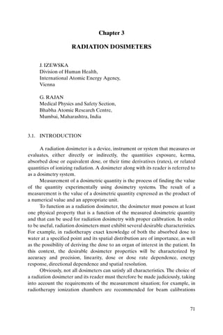
  • 1. Chapter 3 RADIATION DOSIMETERS J. IZEWSKA Division of Human Health, International Atomic Energy Agency, Vienna G. RAJAN Medical Physics and Safety Section, Bhabha Atomic Research Centre, Mumbai, Maharashtra, India 3.1. INTRODUCTION A radiation dosimeter is a device, instrument or system that measures or evaluates, either directly or indirectly, the quantities exposure, kerma, absorbed dose or equivalent dose, or their time derivatives (rates), or related quantities of ionizing radiation. A dosimeter along with its reader is referred to as a dosimetry system. Measurement of a dosimetric quantity is the process of finding the value of the quantity experimentally using dosimetry systems. The result of a measurement is the value of a dosimetric quantity expressed as the product of a numerical value and an appropriate unit. To function as a radiation dosimeter, the dosimeter must possess at least one physical property that is a function of the measured dosimetric quantity and that can be used for radiation dosimetry with proper calibration. In order to be useful, radiation dosimeters must exhibit several desirable characteristics. For example, in radiotherapy exact knowledge of both the absorbed dose to water at a specified point and its spatial distribution are of importance, as well as the possibility of deriving the dose to an organ of interest in the patient. In this context, the desirable dosimeter properties will be characterized by accuracy and precision, linearity, dose or dose rate dependence, energy response, directional dependence and spatial resolution. Obviously, not all dosimeters can satisfy all characteristics. The choice of a radiation dosimeter and its reader must therefore be made judiciously, taking into account the requirements of the measurement situation; for example, in radiotherapy ionization chambers are recommended for beam calibrations 71
  • 2. CHAPTER 3 (reference dosimetry: see Chapter 9) and other dosimeters, such as those discussed below, are suitable for the evaluation of the dose distribution (relative dosimetry) or dose verification. 3.2. PROPERTIES OF DOSIMETERS 3.2.1. Accuracy and precision In radiotherapy dosimetry the uncertainty associated with the measurement is often expressed in terms of accuracy and precision. The precision of dosimetry measurements specifies the reproducibility of the measurements under similar conditions and can be estimated from the data obtained in repeated measurements. High precision is associated with a small standard deviation of the distribution of the measurement results. The accuracy of dosimetry measurements is the proximity of their expectation value to the ‘true value’ of the measured quantity. Results of measurements cannot be absolutely accurate and the inaccuracy of a measurement result is charac- terized as ‘uncertainty’. The uncertainty is a parameter that describes the dispersion of the measured values of a quantity; it is evaluated by statistical methods (type A) or by other methods (type B), has no known sign and is usually assumed to be symmetrical. The error of measurement is the difference between the measured value of a quantity and the true value of that quantity. ● An error has both a numerical value and a sign. ● Typically, the measurement errors are not known exactly, but they are estimated in the best possible way, and, where possible, compensating corrections are introduced. ● After application of all known corrections, the expectation value for errors should be zero and the only quantities of concern are the uncer- tainties. 3.2.1.1. Type A standard uncertainties If a measurement of a dosimetric quantity x is repeated N times, then the best estimate for x is x, the arithmetic mean value of all measurements xi: 72
  • 3. RADIATION DOSIMETERS N Âx 1 x= i (3.1) N i =1 The standard deviation sx characterizes the average uncertainty for an individual result xi and is given by: N Â 1 sx = (x - x) 2 (3.2) N - 1 i =1 i The standard deviation of the mean value is given by: N Â (x 1 1 sx = sx = - x)2 (3.3) N N ( N - 1) i =1 i ● The standard uncertainty of type A, denoted uA, is defined as the standard deviation of the mean value, uA = s x . ● The standard uncertainty of type A is obtained by a statistical analysis of repeated measurements and, in principle, can be reduced by increasing the number of measurements. 3.2.1.2. Type B standard uncertainties Type B standard uncertainties uB cannot be estimated by repeated measurements; rather, they are intelligent guesses or scientific judgements of non-statistical uncertainties associated with the measurement. They include influences on the measuring process, application of correction factors or physical data taken from the literature. It is often assumed that type B standard uncertainties have a probability distribution, such as a normal (Gaussian) or a rectangular distribution (equal probability anywhere within the given limits). Type B standard uncertainties can be derived by estimating the limit beyond which the value of the factor is not going to lie, and a fraction of this limit is taken as uB. The fraction is chosen according to the distribution assumed. 3.2.1.3. Combined and expanded uncertainties The equation that determines a dosimetric quantity Q at a point P is of the type: 73
  • 4. CHAPTER 3 N Q P = M P Fi (3.4) i =1 where M is the reading provided by the dosimetry system and Fi is the correction or conversion coefficient. ● The combined standard uncertainty uC associated with the quantity Q is a quadratic summation of type A (uA) and type B (uB) uncertainties: uC = u A + u B 2 2 (3.5) ● The combined uncertainty is assumed to exhibit a normal distribution and is multiplied by a coverage factor, denoted by k, to obtain the expanded uncertainty U = kuC. The result of the measurement of the quantity Q is then expressed by QP ± U. ● The expanded uncertainty U with the coverage factor k = 2, corre- sponding to the 95% confidence level, is often used to represent the overall uncertainty, which relates to the accuracy of the measurement of the quantity Q. 3.2.2. Linearity Ideally, the dosimeter reading M should be linearly proportional to the dosimetric quantity Q. However, beyond a certain dose range a non-linearity sets in. The linearity range and the non-linearity behaviour depend on the type of dosimeter and its physical characteristics. Two typical examples of response characteristics of dosimetry systems are shown in Fig. 3.1. Curve A first exhibits linearity with dose, then a supralinear behaviour, and finally saturation. Curve B first exhibits linearity and then saturation at high doses. In general, a non-linear behaviour should be corrected for. A dosimeter and its reader may both exhibit non-linear characteristics, but their combined effect could produce linearity over a wider range. 3.2.3. Dose rate dependence Integrating systems measure the integrated response of a dosimetry system. For such systems the measured dosimetric quantity should be independent of the rate of that quantity. 74
  • 5. RADIATION DOSIMETERS A Dosimeter reading B Dose FIG. 3.1. Response characteristics of two dosimetry systems. Curve A first exhibits linearity with dose, then supralinear behaviour and finally saturation. Curve B first exhibits linearity and then saturation at high doses. Ideally, the response of a dosimetry system M/Q at two different dose rates ((dQ/dt)1 and (dQ/dt)2) should remain constant. In reality, the dose rate may influence the dosimeter readings and appropriate corrections are necessary, for example recombination corrections for ionization chambers in pulsed beams. 3.2.4. Energy dependence The response of a dosimetry system M/Q is generally a function of radiation beam quality (energy). Since the dosimetry systems are calibrated at a specified radiation beam quality (or qualities) and used over a much wider energy range, the variation of the response of a dosimetry system with radiation quality (called energy dependence) requires correction. Ideally, the energy response should be flat (i.e. the system calibration should be independent of energy over a certain range of radiation qualities). In reality, the energy correction has to be included in the determination of the quantity Q for most measurement situations. Ιn radiotherapy, the quantity of interest is the dose to water (or to tissue). As no dosimeter is water or tissue equivalent for all radiation beam qualities, the energy dependence is an important characteristic of a dosimetry system. 75
  • 6. CHAPTER 3 3.2.5. Directional dependence The variation in response of a dosimeter with the angle of incidence of radiation is known as the directional, or angular, dependence of the dosimeter. Dosimeters usually exhibit directional dependence, due to their constructional details, physical size and the energy of the incident radiation. Directional dependence is important in certain applications, for example in in vivo dosimetry while using semiconductor dosimeters. Therapy dosimeters are generally used in the same geometry as that in which they are calibrated. 3.2.6. Spatial resolution and physical size Since the dose is a point quantity, the dosimeter should allow the determi- nation of the dose from a very small volume (i.e. one needs a ‘point dosimeter’ to characterize the dose at a point). Τhe position of the point where the dose is determined (i.e. its spatial location) should be well defined in a reference coordinate system. Thermoluminescent dosimeters (TLDs) come in very small dimensions and their use, to a great extent, approximates a point measurement. Film dosimeters have excellent 2-D and gels 3-D resolution, where the point measurement is limited only by the resolution of the evaluation system. Ionization chamber type dosimeters, however, are of finite size to give the required sensitivity, although the new type of pinpoint microchambers partially overcomes the problem. 3.2.7. Readout convenience Direct reading dosimeters (e.g. ionization chambers) are generally more convenient than passive dosimeters (i.e. those that are read after due processing following the exposure, for example TLDs and films). While some dosimeters are inherently of the integrating type (e.g. TLDs and gels), others can measure in both integral and differential modes (ionization chambers). 3.2.8. Convenience of use Ionization chambers are reusable, with no or little change in sensitivity within their lifespan. Semiconductor dosimeters are reusable, but with a gradual loss of sensitivity within their lifespan; however, some dosimeters are not reusable (e.g. films, gels and alanine). Some dosimeters measure dose distribution in a single exposure (e.g. films and gels) and some dosimeters are 76
  • 7. RADIATION DOSIMETERS quite rugged (i.e. handling will not influence sensitivity, for example ionization chambers), while others are sensitive to handling (e.g. TLDs). 3.3. IONIZATION CHAMBER DOSIMETRY SYSTEMS 3.3.1. Chambers and electrometers Ionization chambers are used in radiotherapy and in diagnostic radiology for the determination of radiation dose. The dose determination in reference irradiation conditions is also called beam calibration (see Chapter 9 for details). Ionization chambers come in various shapes and sizes, depending upon the specific requirements, but generally they all have the following properties: ● An ionization chamber is basically a gas filled cavity surrounded by a conductive outer wall and having a central collecting electrode (see Fig. 3.2). The wall and the collecting electrode are separated with a high quality insulator to reduce the leakage current when a polarizing voltage is applied to the chamber. ● A guard electrode is usually provided in the chamber to further reduce chamber leakage. The guard electrode intercepts the leakage current and allows it to flow to ground, bypassing the collecting electrode. It also ensures improved field uniformity in the active or sensitive volume of the chamber, with resulting advantages in charge collection. ● Measurements with open air ionization chambers require temperature and pressure correction to account for the change in the mass of air in the chamber volume, which changes with the ambient temperature and pressure. Graphite Central electrode PTCFE Outer electrode Insulator Aluminium Dural FIG. 3.2. Basic design of a cylindrical Farmer type ionization chamber. 77
  • 8. CHAPTER 3 Electrometers are devices for measuring small currents, of the order of 10–9 A or less. An electrometer used in conjunction with an ionization chamber is a high gain, negative feedback, operational amplifier with a standard resistor or a standard capacitor in the feedback path to measure the chamber current or charge collected over a fixed time interval, as shown schematically in Fig. 3.3. 3.3.2. Cylindrical (thimble type) ionization chambers The most popular cylindrical ionization chamber is the 0.6 cm3 chamber designed by Farmer and originally manufactured by Baldwin, but now available from several vendors, for beam calibration in radiotherapy dosimetry. Its chamber sensitive volume resembles a thimble, and hence the Farmer type chamber is also known as a thimble chamber. A schematic diagram of a Farmer type thimble ionization chamber is shown in Fig. 3.2; ionization chamber based dosimetry systems are discussed in Section 9.2. Cylindrical chambers are produced by various manufacturers, with active volumes between 0.1 and 1 cm3. They typically have an internal length no greater than 25 mm and an internal diameter no greater than 7 mm. The wall material is of low atomic number Z (i.e. tissue or air equivalent), with the thickness less than 0.1 g/cm2. A chamber is equipped with a buildup cap with a thickness of about 0.5 g/cm2 for calibration free in air using 60Co radiation. The chamber construction should be as homogeneous as possible, although an aluminium central electrode of about 1 mm in diameter is typically Cf Rf - + I V = II Rf (rate mode) Rf = feedback resistor V = (II – t)/Cf (variable to vary sensitivity) (integrated mode) Cf = feedback capacitor (variable to vary sensitivity) FIG. 3.3. Electrometer in feedback mode of operation. 78
  • 9. RADIATION DOSIMETERS used to ensure flat energy dependence. Construction details of various commercially available cylindrical chambers are given in the IAEA Technical Reports Series (TRS) 277 and TRS 398 codes of practice. The use of the cylindrical chamber in electron and photon beam dosimetry is discussed in Chapter 9. 3.3.3. Parallel-plate (plane-parallel) ionization chambers A parallel-plate ionization chamber consists of two plane walls, one serving as an entry window and polarizing electrode and the other as the back wall and collecting electrode, as well as a guard ring system. The back wall is usually a block of conducting plastic or a non-conducting material (usually Perspex or polystyrene) with a thin conducting layer of graphite forming the collecting electrode and the guard ring system on top. A schematic diagram of a parallel-plate ionization chamber is shown in Fig. 3.4. The parallel-plate chamber is recommended for dosimetry of electron beams with energies below 10 MeV. It is also used for surface dose and depth dose measurements in the buildup region of megavoltage photon beams. Dose measurements in the buildup region of photon beams are discussed in Section 6.13. The characteristics of commercially available parallel-plate chambers and the use of these chambers in electron beam dosimetry are explained in detail in the TRS 381 and TRS 398 codes of practice. Some parallel-plate chambers require significant fluence perturbation correction because they are provided with an inadequate guard width. 3.3.4. Brachytherapy chambers Sources used in brachytherapy are low air kerma rate sources that require chambers of sufficient volume (about 250 cm3 or more) for adequate sensitivity. Well type chambers or re-entrant chambers are ideally suited for calibration and standardization of brachytherapy sources. Figure 3.5 shows a schematic diagram of a well type chamber. Well type chambers should be designed to accommodate sources of the typical sizes and shapes that are in clinical use in brachytherapy and are usually calibrated in terms of the reference air kerma rate. 3.3.5. Extrapolation chambers Extrapolation chambers are parallel-plate chambers with a variable sensitive volume. They are used in the measurement of surface doses in ortho- 79
  • 10. CHAPTER 3 a Schnitt A–B 3 1 2 3 d m g A B FIG. 3.4. Parallel-plate ionization chamber. 1: the polarizing electrode. 2: the measuring electrode. 3: the guard ring. a: the height (electrode separation) of the air cavity. d: the diameter of the polarizing electrode. m: the diameter of the collecting electrode. g: the width of the guard ring. voltage and megavoltage X ray beams and in the dosimetry of b rays, and low energy X rays. They can also be used in absolute radiation dosimetry when directly embedded into a tissue equivalent phantom. The cavity perturbation for electrons can be eliminated by making measurements as a function of the cavity thickness and then extrapolating to zero thickness. Using this chamber, the cavity perturbation for parallel-plate chambers of finite thickness can be estimated. 80
  • 11. RADIATION DOSIMETERS Source holder Collecting electrode Outer electrode (HV) Insulator To electrometer FIG. 3.5. Basic design of a brachytherapy well type chamber. 3.4. FILM DOSIMETRY 3.4.1. Radiographic film Radiographic X ray film performs several important functions in diagnostic radiology, radiotherapy and radiation protection. It can serve as a radiation detector, a relative dosimeter, a display device and an archival medium. Unexposed X ray film consists of a base of thin plastic with a radiation sensitive emulsion (silver bromide (AgBr) grains suspended in gelatin) coated uniformly on one or both sides of the base. ● Ionization of AgBr grains, as a result of radiation interaction, forms a latent image in the film. This image only becomes visible (film blackening) and permanent subsequently to processing. ● Light transmission is a function of the film opacity and can be measured in terms of optical density (OD) with devices called densitometers. ● The OD is defined as OD = log10 (I0/I) and is a function of dose. I0 is the initial light intensity and I is the intensity transmitted through the film. ● Film gives excellent 2-D spatial resolution and, in a single exposure, provides information about the spatial distribution of radiation in the area of interest or the attenuation of radiation by intervening objects. 81
  • 12. CHAPTER 3 ● Τhe useful dose range of film is limited and the energy dependence is pronounced for lower energy photons. The response of the film depends on several parameters, which are difficult to control. Consistent processing of the film is a particular challenge in this regard. ● Typically, film is used for qualitative dosimetry, but with proper calibration, careful use and analysis film can also be used for dose evaluation. ● Various types of film are available for radiotherapy work (e.g. direct exposure non-screen films for field size verification, phosphor screen films used with simulators and metallic screen films used in portal imaging). ● Unexposed film would exhibit a background OD called the fog density (ODf). The density due to radiation exposure, called the net OD, can be obtained from the measured density by subtracting the fog density. ● OD readers include film densitometers, laser densitometers and automatic film scanners. The principle of operation of a simple film densi- tometer is shown in Fig. 3.6. Ideally, the relationship between the dose and OD should be linear, but this is not always the case. Some emulsions are linear, some are linear over a limited dose range and others are non-linear. The dose versus OD curve, known as the sensitometric curve (also known as the characteristic or H&D curve, in honour of Hurter and Driffield, who first investigated the relationship) must therefore be established for each film before using it for dosimetry work. A typical H&D curve for a radiographic film is shown in Fig. 3.7. It has four regions: (1) fog, at low or zero exposures; (2) toe; (3) a linear portion at Log ratio amplifier Isig _ 2.99 Film I0 + (3½ digits DPM) OD = log10 (I0/Isig) FIG. 3.6. Basic film densitometer. 82
  • 13. RADIATION DOSIMETERS intermediate exposures; and (4) shoulder and saturation at high exposures. The linear portion is referred to as optimum measurement conditions, the toe is the region of underexposure and the shoulder is the region of overexposure. Important parameters of film response to radiation are gamma, latitude and speed: ● The slope of the straight line portion of the H&D curve is called the gamma of the film. ● The exposure should be chosen to make all parts of the radiograph lie on the linear portion of the H&D curve, to ensure the same contrast for all ODs. ● The latitude is defined as the range of exposures over which the ODs will lie in the linear region. ● The speed of a film is determined by giving the exposure required to produce an OD of 1.0 greater than the OD of fog. Typical applications of a radiographic film in radiotherapy are qualitative and quantitative measurements, including electron beam dosimetry, quality control of radiotherapy machines (e.g. congruence of light and radiation fields and the determination of the position of a collimator axis, the so called star 4 (4) Shoulder 3 OD (3) Linear portion 2 1 (1) Fog (2) Toe 0 1 10 100 1000 Exposure (arbitrary units) FIG. 3.7. Typical sensitometric (characteristic H&D) curve for a radiographic film. 83
  • 14. CHAPTER 3 test), verification of treatment techniques in various phantoms and portal imaging. 3.4.2. Radiochromic film Radiochromic film is a new type of film in radiotherapy dosimetry. The most commonly used is a GafChromic film. It is a colourless film with a nearly tissue equivalent composition (9.0% hydrogen, 60.6% carbon, 11.2% nitrogen and 19.2% oxygen) that develops a blue colour upon radiation exposure. Radiochromic film contains a special dye that is polymerized upon exposure to radiation. The polymer absorbs light, and the transmission of light through the film can be measured with a suitable densitometer. Radiochromic film is self-developing, requiring neither developer nor fixer. Since radio- chromic film is grainless, it has a very high resolution and can be used in high dose gradient regions for dosimetry (e.g. measurements of dose distributions in stereotactic fields and in the vicinity of brachytherapy sources). Dosimetry with radiochromic films has a few advantages over radio- graphic films, such as ease of use; elimination of the need for darkroom facilities, film cassettes or film processing; dose rate independence; better energy characteristics (except for low energy X rays of 25 kV or less); and insensitivity to ambient conditions (although excessive humidity should be avoided). Radiochromic films are generally less sensitive than radiographic films and are useful at higher doses, although the dose response non-linearity should be corrected for in the upper dose region. ● Radiochromic film is a relative dosimeter. If proper care is taken with calibration and the environmental conditions, a precision better than 3% is achievable. ● Data on the various characteristics of radiochromic films (e.g. sensitivity, linearity, uniformity, reproducibility and post-irradiation stability) are available in the literature. 3.5. LUMINESCENCE DOSIMETRY Some materials, upon absorption of radiation, retain part of the absorbed energy in metastable states. When this energy is subsequently released in the form of ultraviolet, visible or infrared light, the phenomenon is called lumines- cence. Two types of luminescence, fluorescence and phosphorescence, are known, which depend on the time delay between stimulation and the emission of light. Fluorescence occurs with a time delay of between 10–10 and 10–8 s; 84
  • 15. RADIATION DOSIMETERS phosphorescence occurs with a time delay exceeding 10–8 s. The process of phosphorescence can be accelerated with a suitable excitation in the form of heat or light. ● If the exciting agent is heat, the phenomenon is known as thermolumines- cence and the material is called a thermoluminescent material, or a TLD when used for purposes of dosimetry. ● If the exciting agent is light, the phenomenon is referred to as optically stimulated luminescence (OSL). As discussed in Section 1.4, the highly energetic secondary charged particles, usually electrons, that are produced in the primary interactions of photons with matter are mainly responsible for the photon energy deposition in matter. In a crystalline solid these secondary charged particles release numerous low energy free electrons and holes through ionizations of atoms and ions. The free electrons and holes thus produced will either recombine or become trapped in an electron or hole trap, respectively, somewhere in the crystal. The traps can be intrinsic or can be introduced in the crystal in the form of lattice imperfections consisting of vacancies or impurities. Two types of trap are known in general: storage traps and recombination centres. ● A storage trap merely traps free charge carriers and releases them during the subsequent (a) heating, resulting in the thermoluminescence process, or (b) irradiation with light, resulting in the OSL process. ● A charge carrier released from a storage trap may recombine with a trapped charge carrier of opposite sign in a recombination centre (luminescence centre). The recombination energy is at least partially emitted in the form of ultraviolet, visible or infrared light that can be measured with photodiodes or photomultiplier tubes (PMTs). 3.5.1. Thermoluminescence Thermoluminescence is thermally activated phosphorescence; it is the most spectacular and widely known of a number of different ionizing radiation induced thermally activated phenomena. Its practical applications range from archaeological pottery dating to radiation dosimetry. In 1968 Cameron, Suntharalingam and Kenney published a book on the thermoluminescence process that is still considered an excellent treatise on the practical aspects of the thermoluminescence phenomenon. A useful phenomenological model of the thermoluminescence mechanism is provided in terms of the band model for 85
  • 16. CHAPTER 3 solids. The storage traps and recombination centres, each type characterized with an activation energy (trap depth) that depends on the crystalline solid and the nature of the trap, are located in the energy gap between the valence band and the conduction band. The states just below the conduction band represent electron traps, the states just above the valence band are hole traps. The trapping levels are empty before irradiation (i.e. the hole traps contain electrons and the electron traps do not). During irradiation the secondary charged particles lift electrons into the conduction band either from the valence band (leaving a free hole in the valence band) or from an empty hole trap (filling the hole trap). The system may approach thermal equilibrium through several means: ● Free charge carriers recombine with the recombination energy converted into heat; ● A free charge carrier recombines with a charge carrier of opposite sign trapped at a luminescence centre, the recombination energy being emitted as optical fluorescence; ● The free charge carrier becomes trapped at a storage trap, and this event is then responsible for phosphorescence or the thermoluminescence and OSL processes. 3.5.2. Thermoluminescent dosimeter systems The TLDs most commonly used in medical applications are LiF:Mg,Ti, LiF:Mg,Cu,P and Li2B4O7:Mn, because of their tissue equivalence. Other TLDs, used because of their high sensitivity, are CaSO4:Dy, Al2O3:C and CaF2:Mn. ● TLDs are available in various forms (e.g. powder, chips, rods and ribbons). ● Before they are used, TLDs need to be annealed to erase the residual signal. Well established and reproducible annealing cycles, including the heating and cooling rates, should be used. A basic TLD reader system consists of a planchet for placing and heating the TLD, a PMT to detect the thermoluminescence light emission and convert it into an electrical signal linearly proportional to the detected photon fluence and an electrometer for recording the PMT signal as a charge or current. A basic schematic diagram of a TLD reader is shown in Fig. 3.8. 86
  • 17. RADIATION DOSIMETERS Electrometer HV Thermoluminescence ~ charge PMT TLD Heater FIG. 3.8. TLD reader. ● The thermoluminescence intensity emission is a function of the TLD temperature T. Keeping the heating rate constant makes the temperature T proportional to time t, and so the thermoluminescence intensity can be plotted as a function of t if a recorder output is available with the TLD measuring system. The resulting curve is called the TLD glow curve. In general, if the emitted light is plotted against the crystal temperature one obtains a thermoluminescence thermogram (Fig. 3.9). ● The peaks in the glow curve may be correlated with trap depths responsible for thermoluminescence emission. ● The main dosimetric peak of the LiF:Mg,Ti glow curve between 180ºC and 260ºC is used for dosimetry. The peak temperature is high enough so as not to be affected by room temperature and still low enough so as not to interfere with black body emission from the heating planchet. ● The total thermoluminescence signal emitted (i.e. the area under the appropriate portion of the glow curve) can be correlated to dose through proper calibration. ● Good reproducibility of heating cycles during the readout is important for accurate dosimetry. ● The thermoluminescence signal decreases in time after the irradiation due to spontaneous emission of light at room temperature. This process is called fading. Typically, for LiF:Mg,Ti, the fading of the dosimetric peak does not exceed a few per cent in the months after irradiation. ● The thermoluminescence dose response is linear over a wide range of doses used in radiotherapy, although it increases in the higher dose region, exhibiting supralinear behaviour before it saturates at even higher doses. 87
  • 18. CHAPTER 3 1.0 Time after irradiation Normalized thermolumescence signal 1h 0.8 4d 20 d 0.6 0.4 0.2 0.0 0 50 100 150 200 250 300 350 400 Temperature (˚C) FIG. 3.9. A typical thermogram (glow curve) of LiF:Mg,Ti measured with a TLD reader at a low heating rate. ● TLDs need to be calibrated before they are used (thus they serve as relative dosimeters). To derive the absorbed dose from the thermolumi- nescence reading a few correction factors have to be applied, such as those for energy, fading and dose response non-linearity. ● Typical applications of TLDs in radiotherapy are: in vivo dosimetry on patients (either as a routine quality assurance procedure or for dose monitoring in special cases, for example complicated geometries, dose to critical organs, total body irradiation (TBI), brachytherapy); verification of treatment techniques in various phantoms (e.g. anthropomorphic phantoms); dosimetry audits (such as the IAEA–World Health Organi- zation (WHO) TLD postal dose audit programme); and comparisons among hospitals. 3.5.3. Optically stimulated luminescence systems OSL is based on a principle similar to that of thermoluminescence dosimetry. Instead of heat, light (from a laser) is used to release the trapped energy in the form of luminescence. OSL is a novel technique offering a 88
  • 19. RADIATION DOSIMETERS potential for in vivo dosimetry in radiotherapy. The integrated dose measured during irradiation can be evaluated using OSL directly afterwards. The optical fibre optically stimulated thermoluminescent dosimeter consists of a small (~1 mm3) chip of carbon doped aluminium oxide (Al2O3:C) coupled with a long optical fibre, a laser, a beam splitter and a collimator, a PMT, electronics and software. To produce OSL, the chip is excited with laser light through an optical fibre, and the resulting luminescence (blue light) is carried back in the same fibre, reflected through 90º by the beam splitter and measured in a PMT. The optical fibre dosimeter exhibits high sensitivity over the wide range of dose rates and doses used in radiotherapy. The OSL response is generally linear and independent of energy as well as the dose rate, although the angular response requires correction. Various experimental set-ups exist, such as pulsed OSL or OSL used in conjunction with radioluminescence. Radioluminescence is emitted promptly at the time of dosimeter irradiation and provides information on the dose rate during irradiation, while OSL provides the integrated dose thereafter. This technique, although not yet used routinely in radiotherapy, may prove to be a valuable tool for in vivo dosimetry in the future. 3.6. SEMICONDUCTOR DOSIMETRY 3.6.1. Silicon diode dosimetry systems A silicon diode dosimeter is a p–n junction diode. The diodes are produced by taking n type or p type silicon and counter-doping the surface to produce the opposite type material. These diodes are referred to as n–Si or p– Si dosimeters, depending upon the base material. Both types of diode are commercially available, but only the p–Si type is suitable for radiotherapy dosimetry, since it is less affected by radiation damage and has a much smaller dark current. Radiation produces electron–hole (e–h) pairs in the body of the dosimeter, including the depletion layer. The charges (minority charge carriers) produced in the body of the dosimeter, within the diffusion length, diffuse into the depleted region. They are swept across the depletion region under the action of the electric field due to the intrinsic potential. In this way a current is generated in the reverse direction in the diode. 89
  • 20. CHAPTER 3 ● Diodes are used in the short circuit mode, since this mode exhibits a linear relationship between the measured charge and dose. They are usually operated without an external bias to reduce leakage current. ● Diodes are more sensitive and smaller in size than typical ionization chambers. They are relative dosimeters and should not be used for beam calibration, since their sensitivity changes with repeated use due to radiation damage. ● Diodes are particularly useful for measurement in phantoms, for example of small fields used in stereotactic radiosurgery or high dose gradient areas such as the penumbra region. They are also often used for measure- ments of depth doses in electron beams. For use with beam scanning devices in water phantoms, they are packaged in a waterproof encapsu- lation. When used in electron beam depth dose measurements, diodes measure directly the dose distribution (in contrast to the ionization measured by ionization chambers). ● Diodes are widely used in routine in vivo dosimetry on patients or for bladder or rectum dose measurements. Diodes for in vivo dosimetry are provided with buildup encapsulation and hence must be appropriately chosen, depending on the type and quality of the clinical beams. The encapsulation also protects the fragile diode from physical damage. ● Diodes need to be calibrated when they are used for in vivo dosimetry, and several correction factors have to be applied for dose calculation. The sensitivity of diodes depends on their radiation history, and hence the calibration has to be repeated periodically. ● Diodes show a variation in dose response with temperature (this is partic- ularly important for long radiotherapy treatments), dependence of signal on the dose rate (care should be taken for different source to skin distances), angular (directional) dependence and energy dependence even for small variations in the spectral composition of radiation beams (important for the measurement of entrance and exit doses). 3.6.2. MOSFET dosimetry systems A metal-oxide semiconductor field effect transistor (MOSFET), a miniature silicon transistor, possesses excellent spatial resolution and offers very little attenuation of the beam due to its small size, which is particularly useful for in vivo dosimetry. MOSFET dosimeters are based on the measurement of the threshold voltage, which is a linear function of absorbed dose. Ionizing radiation penetrating the oxide generates charge that is permanently trapped, thus causing a change in threshold voltage. The integrated dose may be measured during or after irradiation. MOSFETs 90
  • 21. RADIATION DOSIMETERS require a connection to a bias voltage during irradiation. They have a limited lifespan. ● A single MOSFET dosimeter can cover the full energy range of photons and electrons, although the energy response should be examined, since it varies with radiation quality. For megavoltage beams, however, MOSFETs do not require energy correction, and a single calibration factor can be used. ● MOSFETs exhibit small axial anisotropy (±2% for 360º) and do not require dose rate corrections. ● Similarly to diodes, single MOSFETs exhibit a temperature dependence, but this effect has been overcome by specially designed double detector MOSFET systems. In general, they show non-linearity of response with the total absorbed dose; however, during their specified lifespan, MOSFETs retain adequate linearity. MOSFETs are also sensitive to changes in the bias voltage during irradiation (it must be stable), and their response drifts slightly after the irradiation (the reading must be taken in a specified time after exposure). ● MOSFETs have been in use for the past few years in a variety of radio- therapy applications for in vivo and phantom dose measurements, including routine patient dose verification, brachytherapy, TBI, intensity modulated radiotherapy (IMRT), intraoperative radiotherapy and radio- surgery. They are used with or without additional buildup, depending on the application. 3.7. OTHER DOSIMETRY SYSTEMS 3.7.1. Alanine/electron paramagnetic resonance dosimetry system Alanine, one of the amino acids, pressed in the form of rods or pellets with an inert binding material, is typically used for high dose dosimetry. The dosimeter can be used at a level of about 10 Gy or more with sufficient precision for radiotherapy dosimetry. The radiation interaction results in the formation of alanine radicals, the concentration of which can be measured using an electron paramagnetic resonance (known also as electron spin resonance) spectrometer. The intensity is measured as the peak to peak height of the central line in the spectrum. The readout is non-destructive. ● Alanine is tissue equivalent and requires no energy correction within the quality range of typical therapeutic beams. It exhibits very little fading for 91
  • 22. CHAPTER 3 many months after irradiation. The response depends on environmental conditions during irradiation (temperature) and storage (humidity). ● At present, alanine’s potential application for radiotherapy is in dosimetry comparisons among hospitals. 3.7.2. Plastic scintillator dosimetry system Plastic scintillators are a relatively new development in radiotherapy dosimetry. The light generated in the scintillator during its irradiation is carried away by an optical fibre to a PMT located outside the irradiation room. A typical set-up requires two sets of optical fibres, which are coupled to two different PMTs, allowing subtraction of the background Cerenkov radiation from the measured signal. The response of the scintillation dosimeter is linear in the dose range of therapeutic interest. Plastic scintillators are almost water equivalent in terms of electron density and atomic composition. Typically, they match the water mass stopping power and mass energy absorption coefficient to within ±2% for the range of beam energies in clinical use, including the kilovoltage region. Scintillators are nearly energy independent and can thus be used directly for relative dose measurements. ● Plastic scintillation dosimeters can be made very small (about 1 mm3 or less) and yet give adequate sensitivity for clinical dosimetry. Hence they can be used in cases where high spatial resolution is required (e.g. high dose gradient regions, buildup regions, interface regions, small field dosimetry and doses very close to brachytherapy sources). Due to flat energy dependence and small size, plastic scintillators are ideal dosimeters for brachytherapy applications. ● Dosimetry based on plastic scintillators is characterized by good repro- ducibility and long term stability. Scintillators suffer no significant radiation damage (up to about 10 kGy), although the light yield should be monitored when used clinically. ● Plastic scintillators are independent of dose rate and can be used from 10 mGy/min (ophthalmic plaque dosimetry) to about 10 Gy/min (external beam dosimetry). They have no significant directional dependence and need no ambient temperature or pressure corrections. 3.7.3. Diamond dosimeters Diamonds change their resistance upon radiation exposure. When applying a bias voltage, the resulting current is proportional to the dose rate of 92
  • 23. RADIATION DOSIMETERS radiation. Commercially available diamond dosimeters are designed to measure relative dose distributions in high energy photon and electron beams. The dosimeter is based on a natural diamond crystal sealed in a polystyrene housing with a bias applied through thin golden contacts. ● Diamonds have a small sensitive volume, of the order of a few cubic milli- metres, which allows the measurement of dose distributions with an excellent spatial resolution. ● Diamond dosimeters are tissue equivalent and require nearly no energy correction. Owing to their flat energy response, small physical size and negligible directional dependence, diamonds are well suited for use in high dose gradient regions, for example for stereotactic radiosurgery. ● In order to stabilize their dose response, diamonds should be irradiated prior to each use to reduce the polarization effect. They exhibit some dependence of the signal on the dose rate, which has to be corrected for when measuring a given physical quality (e.g. depth dose). Also, they have an insignificant temperature dependence, of the order of 0.1%/ºC or less. ● High sensitivity and resistance to radiation damage are other important features of diamond dosimeters. They are waterproof and can be used for measurements in a water phantom. 3.7.4. Gel dosimetry systems Gel dosimetry systems are the only true 3-D dosimeters suitable for relative dose measurements. The dosimeter is at the same time a phantom that can measure absorbed dose distribution in a full 3-D geometry. Gels are nearly tissue equivalent and can be moulded to any desired shape or form. Gel dosimetry can be divided into two types: ● Fricke gels based on the well established Fricke dosimetry; ● Polymer gels. In Fricke gels, Fe2+ ions in ferrous sulphate solutions are dispersed throughout gelatin, agarose or PVA matrix. Radiation induced changes are either due to direct absorption of radiation or via intermediate water free radicals. Upon radiation exposure, ferrous ions Fe2+ are converted into ferric ions Fe3+ with a corresponding change in paramagnetic properties that may be measured using nuclear magnetic resonance (NMR) relaxation rates or optical techniques. A 3-D image of the dose distribution is created. A major limitation of Fricke gel systems is the continual post-irradiation diffusion of ions, resulting in a blurred dose distribution. 93
  • 24. CHAPTER 3 In polymer gel, monomers such as acrylamid are dispersed in a gelatin or agarose matrix. Upon radiation exposure, monomers undergo a polymerization reaction, resulting in a 3-D polymer gel matrix that is a function of absorbed dose that can be evaluated using NMR, X ray computed tomography (CT), optical tomography, vibrational spectroscopy or ultrasound. ● A number of polymer gel formulations are available, including polyacryl- amide gels, generally referred to as PAG gels (e.g. BANG gel), and the new normoxic gels (e.g. MAGIC gel); the latter are not sensitive to the presence of atmospheric oxygen. ● There is a semilinear relationship between the NMR relaxation rate and the absorbed dose at a point in the gel dosimeter. Hence, by mapping the relaxation rates using an NMR scanner, the dose map can be derived by computation and by proper calibration. ● Due to the large proportion of water, polymer gels are nearly water equivalent and no energy corrections are required for photon and electron beams used in radiotherapy. ● No significant dose rate effects in polymer gels have been observed using NMR evaluation, although dose response depends on the temperature at which the dosimeter is evaluated. The strength of the magnetic field during evaluation may also influence the dose response. Care should be taken of post-irradiation effects such as continual polymerization, gelation and strengthening of the gel matrix, which may lead to image distortion. ● Gel dosimetry is a highly promising relative dosimetry technique that may prove particularly useful for dose verification in complex clinical situations (e.g. IMRT), in anatomically shaped phantoms, and for evaluation of doses in brachytherapy, including cardiovascular brachy- therapy. 3.8. PRIMARY STANDARDS Primary standards are instruments of the highest metrological quality that permit determination of the unit of a quantity from its definition, the accuracy of which has been verified by comparison with standards of other institutions of the same level. Primary standards are realized by the primary standards dosimetry laboratories (PSDLs) in about 20 countries worldwide. Regular international comparisons between the PSDLs, and with the Bureau international des poids et mesures (BIPM), ensure international consistency of the dosimetry standards. 94
  • 25. RADIATION DOSIMETERS Ionization chambers used in hospitals for calibration of radiotherapy beams must have a calibration traceable (directly or indirectly) to a primary standard. Primary standards are not used for routine calibrations, since they represent the unit for the quantity at all times. Instead, the PSDLs calibrate secondary standard dosimeters for secondary standards dosimetry laboratories (SSDLs) that in turn are used for calibrating the reference instruments of users, such as therapy level ionization chambers used in hospitals. 3.8.1. Primary standard for air kerma in air Free-air ionization chambers are the primary standard for air kerma in air for superficial and orthovoltage X rays (up to 300 kV); they cannot function as a primary standard for 60Co beams, since the air column surrounding the sensitive volume (for establishing the electronic equilibrium condition in air) would become very long. This would make the chamber very bulky and the various required corrections and their uncertainties would become problematic. ● At 60Co energy, graphite cavity ionization chambers with an accurately known chamber volume are used as the primary standard. ● The use of the graphite cavity chamber is based on the Bragg–Gray cavity theory. 3.8.2. Primary standards for absorbed dose to water The standards for absorbed dose to water enable therapy level ionization chambers to be calibrated directly in terms of absorbed dose to water instead of air kerma in air. This simplifies the dose determination procedure at the hospital level and improves the accuracy compared with the air kerma based formalism. Standards for absorbed dose to water calibration are now available for 60Co beams in several PSDLs, some of which have extended their calibration services to high energy photon and electron beams from acceler- ators. Ideally, the primary standard for absorbed dose to water should be a water calorimeter that would be an integral part of a water phantom and would measure the dose under reference conditions. However, difficulties in the establishment of this standard have led to the development of a primary standard of absorbed dose in various different ways. At present there are three basic methods used for the determination of absorbed dose to water at the primary standard level: (1) the ionometric method; (2) the total absorption method based on chemical dosimetry; and 95
  • 26. CHAPTER 3 (3) calorimetry. The three methods are discussed below and in more detail in Chapter 9. 3.8.3. Ionometric standard for absorbed dose to water A graphite cavity ionization chamber with an accurately known active volume, constructed as a close approximation to a Bragg–Gray cavity, is used in a water phantom at a reference depth. Absorbed dose to water at the reference point is derived from the cavity theory using the mean specific energy imparted to the air in the cavity and the restricted stopping power ratio of the wall material to the cavity gas. The BIPM maintains an ionometric standard of absorbed dose to water. 3.8.4. Chemical dosimetry standard for absorbed dose to water In chemical dosimetry systems the dose is determined by measuring the chemical change produced in the medium (the sensitive volume of the dosimeter) using a suitable measuring system. ● The most widely used chemical dosimetry standard is the Fricke dosimeter. ● The Fricke solution has the following composition: 1mM FeSO4 or Fe(NH4)2(SO4)2 + 0.8N H2SO4 air saturated + 1mM NaCl. 2+ ● Irradiation of a Fricke solution oxidizes ferrous ions Fe into ferric ions Fe ; the latter exhibit a strong absorption peak at l = 304 nm, whereas 3+ ferrous ions do not show any absorption at this wavelength. ● Radiation induced ferric ion concentration can be determined using spectro- photometry, which measures the absorbance (in OD units) of the solution. ● The Fricke dosimeter response is expressed in terms of its sensitivity, known as the radiation chemical yield, G value, and defined as the number of moles of ferric ions produced per joule of the energy absorbed in the solution. ● The chemical dosimetry standard is realized by the calibration of a transfer dosimeter in a total absorption experiment and the subsequent application of the transfer dosimeter in a water phantom, in reference conditions. ● The response of the Fricke solution is determined first using the total absorption of an electron beam. An accurate determination of the energy response of the transfer instrument is necessary (i.e. knowing the electron energy, the beam current and the absorbing mass accurately, the total absorbed energy can be determined and related to the change in 96
  • 27. RADIATION DOSIMETERS absorbance of the Fricke solution). Next, the absorbed dose to water at the reference point in a water phantom is obtained using the Fricke dosimeter as the transfer dosimeter. 3.8.5. Calorimetric standard for absorbed dose to water Calorimetry is the most fundamental method of realizing the primary standard for absorbed dose, since temperature rise is the most direct consequence of energy absorption in a medium. Graphite is in general an ideal material for calorimetry, since it is of low atomic number Z and all the absorbed energy reappears as heat, without any loss of heat in other mechanisms (such as the heat defect). The graphite calorimeter is used by several PSDLs to determine the absorbed dose to graphite in a graphite phantom. The conversion to absorbed dose to water at the reference point in a water phantom may be performed by an application of the photon fluence scaling theorem or by measurements based on cavity ionization theory. ● Graphite calorimeters are electrically calibrated by depositing a known amount of electrical energy into the core. ● Water calorimeters offer a more direct determination of the absorbed dose to water at the reference point in a water phantom. The absorbed dose to water is derived from the measured temperature rise at a point in water, relying on an accurate knowledge of the specific heat capacity. No scaling laws are required, as in the case of graphite calorimetry; however, there are corrections that need to be introduced to compensate for technical complications related to a heat defect due to water radiolysis and heat transport. ● Water calorimeters are calibrated through the calibration of their thermistors in terms of the absolute temperature difference rather than through energy deposition, as is the case for graphite calorimeters. 3.9. SUMMARY OF SOME COMMONLY USED DOSIMETRIC SYSTEMS Radiation dosimeters and dosimetry systems come in many shapes and forms, and they rely on numerous physical effects for storage and readout of the dosimetric signal. The four most commonly used radiation dosimeters are: ● Ionization chambers; ● Radiographic films; 97
  • 28. CHAPTER 3 ● TLDs; ● Diodes. The strengths and weaknesses of these four dosimeters are summarized in Table 3.1. TABLE 3.1. MAIN ADVANTAGES AND DISADVANTAGES OF THE FOUR COMMONLY USED DOSIMETRIC SYSTEMS Advantage Disadvantage Ionization Accurate and precise Connecting cables required chamber Recommended for beam High voltage supply required calibration Many corrections required for Necessary corrections well high energy beam dosimetry understood Instant readout Film 2-D spatial resolution Darkroom and processing Very thin: does not perturb facilities required the beam Processing difficult to control Variation between films and batches Needs proper calibration against ionization chamber measurements Energy dependence problems Cannot be used for beam calibration TLD Small in size: point dose Signal erased during readout measurements possible Easy to lose reading Many TLDs can be exposed No instant readout in a single exposure Accurate results require care Available in various forms Readout and calibration time Some are reasonably tissue consuming equivalent Not recommended for beam Not expensive calibration Diode Small size Requires connecting cables High sensitivity Variability of calibration with Instant readout temperature No external bias voltage Change in sensitivity with Simple instrumentation accumulated dose Special care needed to ensure constancy of response Cannot be used for beam calibration 98
  • 29. RADIATION DOSIMETERS BIBLIOGRAPHY ATTIX, F.H., Introduction to Radiological Physics and Radiation Dosimetry, Wiley, New York (1986). CAMERON, J.R., SUNTHARALINGAM, N., KENNEY, G.K., Thermoluminescent Dosimetry, University of Wisconsin Press, Madison, WI (1968). HORTON, J., Handbook of Radiation Therapy Physics, Prentice Hall, New York (1987). INTERNATIONAL ATOMIC ENERGY AGENCY, Absorbed Dose Determination in Photon and Electron Beams, Technical Reports Series No. 277, IAEA, Vienna (1987). — Calibration of Dosimeters Used in Radiotherapy, Technical Reports Series No. 374, IAEA, Vienna (1994). — The Use of Plane Parallel Ionization Chambers in High Energy Electron and Photon Beams, Technical Reports Series No. 381, IAEA, Vienna (1997). — Absorbed Dose Determination in External Beam Radiotherapy, Technical Reports Series No. 398, IAEA, Vienna (2000). INTERNATIONAL ORGANIZATION FOR STANDARDIZATION, Guide to Expression of Uncertainty in Measurement, ISO, Geneva (1992). KHAN, F.M., The Physics of Radiation Therapy, Lippincott, Williams and Wilkins, Baltimore, MD (2003). KLEVENHAGEN, S.C., Physics and Dosimetry of Therapy Electron Beams, Medical Physics Publishing, Madison, WI (1993). VAN DYK, J. (Ed.), Modern Technology of Radiation Oncology: A Compendium for Medical Physicists and Radiation Oncologists, Medical Physics Publishing, Madison, WI (1999). 99