Recomendados

Recomendados
Más contenido relacionado
La actualidad más candente
La actualidad más candente (20)
Destacado
Similar a poster3
Similar a poster3 (20)
poster3
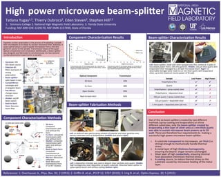
- 1. High power microwave beam-‐spli3er Ta$ana Yugay1,2, Thierry Dubroca2, Eden Steven2, Stephen Hill2,3 1. Simmons College 2. Na$onal High Magne$c Field Laboratory 3. Florida State University Funding: NSF-‐MRI CHE-‐1229170, NSF DMR-‐1157490, State of Florida Introduc9on Component Characteriza9on Methods Dynamic nuclear polariza$on is the process of irradia$ng a sample with microwaves to increase its nuclear resonance lines’ intensity. A quasi-‐op$cal setup is used to guide microwaves from a 395 GHz gyrotron source to the sample. Transmission losses of the quasi-‐ op$cal components were evaluated. Addi$onally, a beam-‐spliWer was designed and fabricated to simultaneously run two dynamic nuclear polariza$on experiments in parallel. Beam-‐spli3er Fabrica9on Methods Le@: an airbrush was used to spray solu$on of polymer and silver par$cles onto various substrates such as polyethylene (middle) and quartz (right). Beam-‐spli3er Characteriza9on Results Conclusion Out of the six beam-‐spliWers created by two different methods (spray-‐coa$ng and evapora$on) on three different substrates, only the beam-‐spli3er created by evapora9ng a thin layer of silver onto a 1 mm thick quartz was able to sustain microwave beam powers up to 50 wa3. There are therefore four requirements to making a successful high power microwave beam-‐spliWer: Component Characteriza9on Results • 3D horn: compared transmission with and without the horn • Cu horn: compared transmission with and without horn • Shu3er: compared transmission with open and without shuWer • Back-‐to-‐back horn: compared transmission at entrance and exit • Mirrors: Measured reflec$on • Grid: Measured transmission from 0° to 90° rota$on. Le@: beam-‐spliWer, made with silver sprayed onto film, melted at 3 waWs of microwave power from a 395 GHz gyrotron. Middle: 150 μm thick quartz with evaporated silver damaged by a 20 waW microwave beam. Right: no observable damages were made to a 1 mm thick quartz with evaporated silver, up to the maximum source power of 50 waW. Op9cal Component Transmission 3D Horn 33% Cu Horn 38% Open ShuWer 99% Back-‐to-‐back Horn 92% Sample Low Power High Power Polyethylene film ✔ ✔ Quartz ✔ ✔ Polyethylene + spray-‐coated silver ✔ ✗ Polyethylene + deposited silver ✔ ✗ 150 μm quartz + spray-‐coated silver ✔ ✗ 150 μm quartz + deposited silver ✔ ✗ 1 mm quartz + deposited silver (20 nm) ✔ ✔ 395 GHz gyrotron 600 MHz NMR magnet References: 1. Overhauser A., Phys. Rev. 92, 2 (1953); 2. Griffin R. et al., PCCP 12, 5737 (2010); 3. Ung B. et al., Op$cs Express. 20, 5 (2012). COPPER HORN 3D HORN PYROMETER BEAM BACK-‐TO-‐BACK HORN GRID SHUTTER FLAT MIRROR CURVED MIRROR BEAM SPLITTER POLARIZER #1 GYROTRON EXPERIMENT 1 EXPERIMENT 2 • Gyrotron: 395 GHz beam source • Polarizer #1: filters out beam of wrong polariza$on • Beam-‐spli3er: splits beam in two • Curved Mirror: converges and propagates beam • Flat Mirror: changes beam direc$on • Shu3er: on/off beam switch • Back-‐to-‐back Horn: Gaussian beam filter 0 20 40 60 80 100 120 0 20 40 60 80 100 120 140 160 Measured Transmission (mW) Distance (mm) 0 50 100 150 200 250 0 10 20 30 40 50 60 70 80 90 100 Measured Transmission (mW) Angle Rotated (Degrees) Measured Malus Law Where beam diameter = 3D horn diameter 100% transmission Transmission plot of microwave power as a func$on of distance between source and 3D horn (blue dots). Linear regression model (solid black). Transmission plot of microwave power as a func$on of rota$on angle of a polariza$on grid (blue dots). Malus Law model overlayed (solid orange). Le@: a deposi$on chamber was used to deposit silver par$cles onto quartz. Middle: high homogeneity silver deposi$on on quartz substrate. Mounted beam-‐spliWer in quasi-‐op$cal bench with airflow cooling (bo3om right). 1. A substrate transparent to microwaves, yet thick (i.e. strong) enough to mechanically handle thermal stress. 2. A metal layer of high thickness homogeneity, ensuring the beams’ shape remains unchanged. 3. Silver layer of high conduc9vity, ensuring minimal heat absorp$on (minimizes thermal stress). 4. A cooling source, to reduce thermal stress on the substrate caused by microwave hea$ng of the metal layer.