Seamless splicing MAX7219 Dot Matrix Module DIY kits

MAX7219 Dot Matrix Module Control Display Module DIY kit Cascade http://www.icstation.com/product_info.php?products_id=2609 - Seamless splicing and so that the dot matrix can be flexible spliced . - Common cathode with bright dot matrix(8*8), display fresh and brilliant picture. - A screen roll freely, to achieve the perfect picture display - Since the master chip is used in Max7219 to- make product have the following characteristics: 1).The transmission efficiency of up to 10MHz. 2).Can be individually controlled for each point. 3).Lowest power consumption of 450uA (one module). 4).Power-on reset automatically display full black 5).Serial communication, a great saving of MCU IO, also can be extended To expand the program with SPI. 6).For each screen brightness control, by setting the Max7219 instructions.

Recomendados
Recomendados
Más contenido relacionado
Último
Último (20)
Destacado
Destacado (20)
Seamless splicing MAX7219 Dot Matrix Module DIY kits
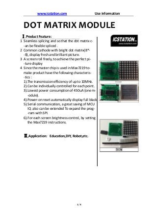
- 1. www.icstation.com Use information 1 / 4 DOT MATRIX MODULE Ⅰ.Product Feature: 1 Seamless splicing and so that the dot matrix c- -an be flexible spliced . 2 Common cathode with bright dot matrix(8*- -8), display fresh and brilliant picture. 3 A screen roll freely, to achieve the perfect pi- -ture display 4 Since the master chip is used in Max7219 to- make product have the following characteris- -tics : 1).The transmission efficiency of up to 10MHz. 2).Can be individually controlled for each point. 3).Lowest power consumption of 450uA (one m- -odule). 4).Power-on reset automatically display full black 5).Serial communication, a great saving of MCU IO, also can be extended To expand the prog- -ram with SPI. 6).For each screen brightness control, by setting the Max7219 instructions. Ⅱ,Application: Education,DIY, Robot,etc.
- 2. www.icstation.com Use information 2 / 4 Ⅲ,ABSOLUTE MAXIMUM RATINGS Ⅳ.PIN Define Pin Function CLK Serial-Clock Input. 10MHz maximum rate. CS Chip-Select Input. Serial data is loaded into the shift register while CSis low. DIN Serial-Data Input. Data is loaded into the internal 16-bit shift register on CLK’s rising edge DOUT Serial-Data Output. The data into DIN is valid at DOUT 16.5 clock cycles later. VCC Positive Supply Voltage. Connect to +5V. GND Ground Note: More information See: referenceMAX7219datasheet.pdf Ⅴ. Physical Diagram (Normally) 1) 2) Voltage (with respect to GND) V+.........................................................-0.3V to 6V DIN, CLK, LOAD, CS..............................-0.3V to 6V Current DIG0–DIG7 Sink Curr............................. 500mA SEGA–G, DP Source Current .................. 100mA Continuous Power Dissipation (TA = +85 °C) Narrow Plastic DIP....................................0.87W Wide SO .................................................. 0.76W Narrow CERDIP..........................................1.1W Operating Temperature Ranges(Max7219) MAX7219............................................. 0°C to +70 °C Storage Temperature Range ..................-65 °C to +160°C Lead Temperature (soldering, 10sec) ......+300°C
- 3. www.icstation.com Use information 3 / 4 Ⅵ.Example 1. Introduce 2. Connect Diagram Note: Jumper cap on both sides are linked This module USES a four product combination showed a Chinese characters, you can see the Chinese character "科" is the perfect display on top of the screen. This routine uses ATmega32 DIP encapsulation microcontroller 3) To Install,Remember these two places must be same side otherwise the function cannot be achieved
- 4. www.icstation.com Use information 4 / 4 Ⅶ.Code : See : codedisplay a character using four device.zip( In this document) Ⅷ. Reference: See: referenceMAX7219datasheet.pdf Ⅸ,Warning: This product designed by icstation and all rights reserved If any problem, please contact us: www.icstation.com Document Revision A