Radial transmission system voltage calculation
•Download as DOC, PDF•
0 likes•810 views

The document contains 5 problems related to synchronous generators feeding power into transmission systems. Problem 1 asks to calculate the terminal voltage of a synchronous machine feeding a 60 MW load at 0.9 power factor. Problem 2 asks to draw a per unit impedance diagram for a power system. Problem 3 provides parameters for a synchronous generator and asks several related calculation questions. Problems 4 and 5 provide additional generator parameters and measurement information, and ask to calculate values like voltage, current, power angle and active/reactive power based on changes to the system.

Recommended
More Related Content
What's hot
What's hot (20)
Similar to Radial transmission system voltage calculation
Similar to Radial transmission system voltage calculation (20)
More from Abha Tripathi
More from Abha Tripathi (16)
Recently uploaded
Recently uploaded (20)
Radial transmission system voltage calculation
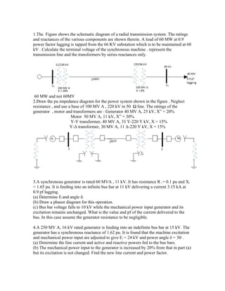
- 1. 1.The Figure shows the schematic diagram of a radial transmission system. The ratings and reactances of the various components are shown therein. A load of 60 MW at 0.9 power factor lagging is tapped from the 66 KV substation which is to be maintained at 60 kV . Calculate the terminal voltage of the synchronous machine . represent the transmission line and the transformers by series reactances only. 60 MW and not 60MV 2.Draw the pu impedance diagram for the power system shown in the figure . Neglect resistance , and use a base of 100 MV A , 220 kV in 50 Ω line. The ratings of the generator , motor and transformers are : Generator 40 MV A, 25 kV, X” = 20% Motor 50 MV A, 11 kV, X” = 30% Y-Y transformer, 40 MV A, 33 Y-220 Y kV, X = 15% Y-Δ transformer, 30 MV A, 11 Δ-220 Y kV, X = 15% 3.A synchronous generator is rated 60 MVA , 11 kV. It has resistance R = 0.1 pu and X a d = 1.65 pu. It is feeding into an infinite bus bar at 11 kV delivering a current 3.15 kA at 0.9 pf lagging. (a) Determine E and angle δ. f (b) Draw a phasor diagram for this operation. (c) Bus bar voltage falls to 10 kV while the mechanical power input generator and its excitation remains unchanged. What is the value and pf of the current delivered to the bus. In this case assume the generator resistance to be negligible. 4.A 250 MV A, 16 kV rated generator is feeding into an indefinite bus bar at 15 kV. The generator has a synchronous reactance of 1.62 pu. It is found that the machine excitation and mechanical power input are adjusted to give E = 24 kV and power angle δ = 30 . f 0 (a) Determine the line current and active and reactive powers fed to the bus bars. (b) The mechanical power input to the generator is increased by 20% from that in part (a) but its excitation is not changed. Find the new line current and power factor.
- 2. (c) With reference to part (a) current is to be reduced by 20% at the same power factor by adjusting mechanical power input to the generator and its excitation. Determine E , δ and f mechanical power input. (d) With the reduced current as in part (c), the power is to be delivered to bus bars at unity pf, what are the corresponding values of E and δ and also the mechanical power f input to the generator. 5.The generator of problem 4 is feeding 150 MV A at 0.85 pf lagging to infinite bus bar at 15 kV. (a) Determine E and δ for the above operation. What are P and Q fed to the bus bars ? f (b) Now E is reduced by 10% keeping mechanical input to generator same, find new δ f and Q delivered. (c) E is now maintained as in part (a) but mechanical power input to generator is adjusted f till Q = 0. Find new δ and P. (d) For the value of E in part (a) what is the maximum Q that can be delivered to bus bar. f What is the corresponding δ and I ? Sketch the phasor diagram for each part. a Answers: 1. 12kV 3. (a) 26.8kV (line), 42.3 leading; (c) 1.13 (-28.8 ) ; 0.876 lag ◦ 0 4. (a) 0.511 (-25.6 ) kA ; 108 MW, 51.75 MVAR ; (b) 6.14 kA, 0.908 lagging ; 0 0 (c) 1.578, 13.5 , 53.3 MW ; (d) 18.37 kV, 35.5 . 96 MW 0 0 5. (a) 25.28 kV, 20.2 , 127.5 MW, 79.05 MVAR ; (b) 33.9 , 54.14 MVAR ; (c) 0 0 41.1 , 54.14 MVAR ; (d) 184.45 MVAR, 53.6 , -j0.787 pu 0 0