SlideShare una empresa de Scribd logo
1 de 46
Synchronous Design Process
1. Construct a state diagram and/or state/output
   table corresponding to the word description or
   specification
2. Minimize the number of states
3. Choose a set of state variables and assign
   state variable combinations to the named
   states
4. Obtain the transition/output table
5. Determine the number of flip-flops and select
   the type of flip-flop to be used (D is often the
   default)
6. Construct the excitation table
7. Derive excitation equations
8. Derive output equations                          1
Design a clocked synchronous state machine
 which detects a sequence of three or more
 consecutive 1’s in a string of bits coming
 through an input line.

Mealy machine with D flip flops
Moore machine with D flip flops
Moore machine with JK flip flops
ealy machine with D flip flops (change of encoding
Assuming Mealy machine design
Let the input be X and output be Z
Obtaining the state Diagram
 Assume initial condition to be Z = 0
 Let the initial state be represented by state
 A
    If X = 0, then output Z = 0, same state A
X/Z     = 1, then output Z = 0, goes to state B
              1/0
0/0      A          B                 Mealy machine


          A    1    B
  0                                  Moore machine
          0         0
Obtaining the state Diagram
 Assume machine has moved to state B
   If X = 0, then output Z = 0, goes back to
 state A
       = 1, then output Z = 0, goes to state C
X/Z

              1/0       1/0
0/0       A         B         C      Mealy machine

              0/0


          A    1    B    1    C
      0                              Moore machine
          0         0         0
               0
Obtaining the state Diagram
 Assume machine has moved to state C
   If X = 0, then output Z = 0, goes back to
 state A
       = 1, then output Z = 1, same state C
X/Z

              1/0         1/0
0/0       A         B           C        1/1 Mealy machine

              0/0   0/0


          A    1    B      1    C0   1     C1
      0                                           1
          0         0            0         1
               0                                  Moore
                     0          0                 machin
Obtaining the state/output table
    Mealy machine                   Moore machine
  State/output table           State/output table
    State      Input X         State      Input X      Output

     S        0      1          S        0      1        Z

     A       A,0    B,0         A        A      B        0

     B       A,0    C,0         B        A     C0        0

     C       A,0    C,1        C0        A     C1        0

                               C1        A     C1        1
            Next State S*, Z

                                       Next State S*
Assigning state variable to obtain
      Mealy machine
transition/output table     Moore machine
                        Transition/output table
  Transition/output table
     State     Input X        State    Input X   Output

     Q1Q0     0      1        Q1Q0    0      1     Z

      00     00,0   01,0       00     00    01     0

      01     00,0   10,0       01     00    10     0

      10     00,0   10,1       10     00    11     0

                               11     00    11     1
       Next State Q1*Q0*, Z
Encoding
A = 00, B =         Choosing D Next State Q1*Q0*
01                  type flip flop
Constructing the excitation table
     Mealy machine               Moore machine
 Excitation/output table Excitation/output table
     State     Input X     State    Input X     Output

     Q1Q0     0      1     Q1Q0     0       1     Z

      00     00,0   01,0    00     00    01       0

      01     00,0   10,0    01     00    10       0

      10     00,0   10,1    10     00    11       0

                            11     00    11       1
              D1D0, Z

                                     D1D0
Transferring onto K-maps to derive excitation
equations (Mealy Machine)
Excitation/      State  Input X              State     Input X
output table     Q1Q0  0       1             Q1Q0     0       1
 State     Input X
                        00     0      0       00      0       1
Q1Q0       0       1
                        01     0      1       01      0       0
  00     00,0   01,0
                        11     X      X       11      X       X
  01     00,0   10,0
                        10     0      1       10      0       0
  10     00,0   10,1
                                D1                    D0
         D1D0, Z       D1 = Q0 ⋅ X + Q1⋅ X     D 0 = Q1 ⋅ Q 0 ⋅ X
Transferring onto K-maps to derive output
 equation (Mealy Machine)
Excitation/output         State       Input X
table
                           Q1Q0      0         1
  State     Input X
                            00       0         0
 Q1Q0       0       1
                            01       0         0
   00     00,0   01,0
                            11       X         X
   01     00,0   10,0
                            10       0         1
   10     00,0   10,1
                                         Z
          D1D0, Z                 Z = Q1 ⋅ X
Circuit (logic) diagram
                      Mealy machine

 D 0 = Q1 ⋅ Q 0 ⋅ X             D1 = Q0 ⋅ X + Q1⋅ Xexcitation equations

                                Z = Q1 ⋅ X              output equation

            X   Q0 Q0' Q1 Q1'

                                                                    Z
                                             D0         Q0
                                                  D Q

                                                    Q


                                             D1 D Q Q1

                                                    Q
      Clk
Transferring onto K-maps to derive excitation
equation (Moore Machine)
Excitation       State  Input X            State     Input X
table           Q1Q0   0       1           Q1Q0     0      1
 State    Input X
                      00      0      0      00      0      1
Q1Q0     0       1
                      01      0      1      01      0      0
  00     00    01
                      11      0      1      11      0      1
  01     00    10
                      10      0      1      10      0      1
  10     00    11
                              D1                    D0
  11     00    11    D1 = Q0 ⋅ X + Q1⋅ X D 0 = Q1 ⋅ X + Q 0 ⋅ X

          D1D0
Transferring onto K-maps to derive output
equation (Moore Machine)
Excitation/output
table
  State  Input X  Output

 Q1Q0   0       1   Z

  00    00   01     0

  01    00   10     0   Z = Q1⋅ Q0

  10    00   11     0

  11    00   11     1

         D1D0
Circuit (logic) diagramMoore machine

D 0 = Q1 ⋅ X + Q 0 ⋅ X    D1 = Q0 ⋅ X + Q1⋅ Xexcitation equations
                          Z = Q1⋅ Q0              output equation

          X   Q0 Q0' Q1
                                                            Z
                                       D0         Q0
                                            D Q

                                              Q


                                       D1 D Q Q1

                                              Q
Clk
Moore machine with JK flip flops
Assigning state variable to obtain
transition/output table
    Transition/output table Excitation table for
      State  Input X  Output JK flip flop
     Q1Q0     0     1      Z    Q    Q*    J   K

      00      00    01     0    0    0    0    X

      01      00    10     0    0    1    1    X

      10      00    11     0    1    0    X    1

      11      00    11     1    1    1    X    0

            Next State Q1*Q0*
Constructing the excitation table

Transition/output table         Excitation/output table
  State      Input X   Output   State         Input X       Output

 Q1Q0       0      1     Z      Q1Q0      0             1     Z

   00       00    01     0       00     0X, 0X 0X, 1X         0

   01       00    10     0       01     0X, X1 1X, X1         0

   10       00    11     0       10     X1, 0X X0, 1X         0

   11       00    11     1       11     X1, X1 X0, X0         1

          Next State Q1*Q0*              J1K1,J0K0
Transferring onto K-maps to derive excitation
equations
Excitation                  State      Input X       State     Input X
table                       Q1Q0      0          1   Q1Q0     0       1
State         Input X
                             00       0          0    00      X       X
Q1Q0      0             1
                             01       0          1    01      X       X
 00     0X, 0X 0X, 1X
                             11       X          X    11      1       0
 01     0X, X1 1X, X1
                             10       X          X    10      1       0
 10     X1, 0X X0, 1X
                                       J1                     K1
 11     X1, X1 X0, X0
                                  J 1 = Q0 ⋅ X               K1 = X

          J1K1,J0K0
Transferring onto K-maps to derive excitation
equations
Excitation                  State     Input X    State      Input X
table                       Q1Q0      0      1   Q1Q0      0      1
State         Input X
                             00       0      1    00       X      X
Q1Q0      0             1
                             01       X      X    01       1      1
 00     0X, 0X 0X, 1X
                             11       X      X    11       1      0
 01     0X, X1 1X, X1
                             10       0      1    10       X      X
 10     X1, 0X X0, 1X
                                      J0                   K0
 11     X1, X1 X0, X0
                                    J0 = X             K 0 = Q1 + X
          J1K1,J0K0
Transferring onto K-maps to derive output
equation
 Excitation/output table
 State         Input X       Output

 Q1Q0      0             1     Z

  00     0X, 0X 0X, 1X         0

  01     0X, X1 1X, X1         0      Z = Q1⋅ Q0
  10     X1, 0X X0, 1X         0

  11     X1, X1 X0, X0         1

          J1K1,J0K0
Circuit (logic) diagram
excitation equations              output equation
 J 1 = Q0 ⋅ X     K1 = X                  Z = Q1⋅ Q0
 J0 = X           K 0 = Q1 + X
  X       X' Q0      Q1'
                                                       Z
                                 J0           Q0
                                      J   Q

                                      K   Q
                                 K0


                                 J1           Q1
                                      J   Q

                                      K   Q
Clk                              K1
Assigning state variable to obtain
transition/output table machine
                   Mealy
               Transition/output table
                   State     Input X

  Change           Q1Q0     0      1
  of                00     00,0   01,0
  Encoding
  A = 00            01     00,0   11,0
  B = 01            11     00,0   11,1
  C = 11
                     Next State Q1*Q0*, Z

                    Choosing D
                    type flip flop
Constructing the excitation table

                   M ealy machine
              Excitation/output table
                   State     Input X

                  Q1Q0      0      1

                    00     00,0   01,0

                    01     00,0   11,0

                    11     00,0   11,1

                            D1D0, Z
Transferring onto K-maps to derive excitation
equations (Mealy Machine)
Excitation/      State  Input X            State     Input X
output table     Q1Q0  0       1           Q1Q0     0       1
 State     Input X
                       00    0         0    00      0       1
Q1Q0       0       1
                       01    0         1    01      0       1
  00     00,0   01,0
                       11    0         1    11      0       1
  01     00,0   11,0
                       10    X         X    10      X       X
  11     00,0   11,1
                             D1                      D0
         D1D0, Z        D1 = Q 0 ⋅ X               D0 = X
Transferring onto K-maps to derive output
 equation (Mealy Machine)
Excitation/output         State       Input X
table
                           Q1Q0      0         1
  State     Input X
                            00       0         0
 Q1Q0       0       1
                            01       0         0
   00     00,0   01,0
                            11       0         1
   01     00,0   11,0
                            10       X         X
   11     00,0   11,1
                                         Z
          D1D0, Z                 Z = Q1 ⋅ X
Circuit (logic) diagram
                      Mealy machine

    D0 = X           D1 = Q0 ⋅ X     excitation equations

                  Z = Q1 ⋅ X            output equation

             X

                                            Z
                     D0         Q0
                          D Q

                            Q


                     D1 D Q Q1

                            Q
       Clk
Example 1: State Diagram
• Design the FSM for the given state diagram
  – Graphical version of states, inputs, transitions and
    outputs


  W             Z


                       State
  X             Y   assignment


Given state diagram               Assigned state diagram

                                                           26
Example 1: State Table
     • For each current-state, specify next-state(s) as
       a function of the present inputs
     • For each current-state, specify the output(s) as
       a function of the present inputs


State Variables

We often use Q0, Q1,
Q2, etc. to acknowledge
that state variables are
F-F outputs


                                                     27
Example 1: Alternate State Table
    • State table, alternate format emphasizing state
      transitions
    • Notation: A → Q(t) and A+ → Q(t+1), used to
      indicate the change in state variable needed
      for the desired transition

 Q1(t) Q0(t) →
Q1(t+1) Q0(t+1)        (             )
    a more
  descriptive
   notation


                                                   28
Example 1: Flip-Flop Excitation Tables
• Use these tables to “move” Q to next state
• Used to design the memory control CL circuit


                      We will use the D F-F      29
Example 1: Flip-Flop Excitation Tables
• Why are we are interested in the D Flip-Flop
  for this design?

                      Q(t)   Q(t+1)   D    Operation
                       0       0      0     Reset
                       0       1      1      Set
                       1       0      0     Reset
                       1       1      1      Set


   We select D Flip-Flops because the D input is
   simply the value of Q(t+1) that we desire


                                                   30
Example 1: Block Diagram
• We need to use two
  D flip-flops              x                        y
                                      (output)
• The sequential circuit
  would look as shown                 (next state)
                                 Q1         D1
• We will design the CL
  for a 3-input, 3-output        Q2         D2
  circuit
  – CL for Output (y)
  – CL for Next State
    controls (D1 and D2)
                                inputs = x, Q1, Q2
                                outputs = y, D1, D2
                                                     31
Example 1: Truth Table
• The truth table for this 3-input, 3-output circuit
  can be generated from the original state table
• We will need to minimize each output function
  using Karnaugh maps, mindful of overlap


            0
            1
            2
            3
minterms    4
            5
            6
            7                                          32
Example 1: Karnaugh Maps
    • Minimizing each of the three outputs:

A+                            B+


            1    1     1           1      1
      A+ = x ∙ Q1 + x ∙ Q2             B+ = x ∙ Q1

y
                                   A = Q1 and B = Q2
            1    1     1


      y = x ∙ Q1 + x ∙ Q2                            33
Example 1: Circuit Diagram
• The circuit that results from these equations is
  shown below:

 y = x ∙ Q1 + x ∙ Q2
 y = x ∙ (Q1 + Q2)


 A+ = x ∙ Q1 + x ∙ Q2
 A+ = x ∙ (Q1 + Q2)

 B+ = x ∙ Q1


                                                 34
Design: Example 2
• Given the state diagram as follows, design the
  sequential circuit using JK Flip-Flops

         D


  A              C


         B           state assignment
                        A = 01
                        B = 10
                        C = 11
                        D = 00
                                                   35
Design: Example 2
• Note that this is a state diagram for a Mealy machine


                     inputs                    outputs
                                                     36
Design: Example 2
• Block diagram, signal identification


                                         Input, x Sequential
                                                    Logic
                                           1-bit   Circuit


                                                      CP


 We need to
  determine
what goes in
      here?                                            37
Design: Example 2
• From state table, get input flip-flop function


                        KB = Ax + A’x’
                        KB = Ax + A’x’             38
Design: Example 2
• Input flip-flop function

                                                       JA
                                   Input, x   A
                                              B
                                                       KA
                                              x        JB
• Logic Diagram                     1-bit              KB


                                                  CP
                          x


            x′ B    A x
      x B


                                                  39
CLK


QA


QD


QC


QB

          0   1     2       3       4       8        9       10        11   12   0


                  101 overlap M oore machine

                        1                        1

              A     1       B           0       C0       1        C1
      0
              0             0                    0                1
                                0
                                                         0
CLK

QD

QC

QB

QA

LD

            5      6     7   8   9   10   11   12   13   14     5

      Initial Counting                                   Reloading
      Loading starts
1110 Moore machine


                                                     1
                0                        1
          A 1        B   1       C   1       D   0       E
      0   0          0       0
                                 0           0           1
                                         0           0
43
State      Input X
                        Output
 S        0      1
                          Z
 A        A      B
                          0
 B        A     C0
                          0
 C        A     C1
                          0
 D        A     C1
                          1

        Next State S*
                              44
X        Q0     Q1
      X'        Q0'

                       D0         Q0
                            D Q

                              Q


                       D1 D Q Q1

                              Q


                       D2 D Q Q2       Z

Clk                           Q
State      Input X      Output

 S        0      1        Z

 A        A      B        0

 B        A     C0        0

C0        A     C1        0

C1        A     C1        1

        Next State S*
                              46

Más contenido relacionado

La actualidad más candente

Modulo n counter
Modulo n counterModulo n counter
Modulo n counterManoj Guha
 
Verilog Test Bench
Verilog Test BenchVerilog Test Bench
Verilog Test BenchDr.YNM
 
MOS-Nonideal charecteristics
MOS-Nonideal charecteristicsMOS-Nonideal charecteristics
MOS-Nonideal charecteristicsShanmuga Raju
 
Analog Electronics interview and viva questions.pdf
Analog Electronics interview and viva questions.pdfAnalog Electronics interview and viva questions.pdf
Analog Electronics interview and viva questions.pdfEngineering Funda
 
NYQUIST CRITERION FOR ZERO ISI
NYQUIST CRITERION FOR ZERO ISINYQUIST CRITERION FOR ZERO ISI
NYQUIST CRITERION FOR ZERO ISIFAIZAN SHAFI
 
module1:Introduction to digital electronics
module1:Introduction to digital electronicsmodule1:Introduction to digital electronics
module1:Introduction to digital electronicschandrakant shinde
 
Design challenges in physical design
Design challenges in physical designDesign challenges in physical design
Design challenges in physical designDeiptii Das
 
J - K & MASTERSLAVE FLIPFLOPS
J - K & MASTERSLAVE FLIPFLOPSJ - K & MASTERSLAVE FLIPFLOPS
J - K & MASTERSLAVE FLIPFLOPSKrishma Parekh
 
3.2 modulation formats bpsk, qpsk, oqpsk,
3.2 modulation formats   bpsk, qpsk, oqpsk,3.2 modulation formats   bpsk, qpsk, oqpsk,
3.2 modulation formats bpsk, qpsk, oqpsk,JAIGANESH SEKAR
 
Synchronous Loadable Up and Down Counter
Synchronous Loadable Up and Down Counter Synchronous Loadable Up and Down Counter
Synchronous Loadable Up and Down Counter Digital System Design
 

La actualidad más candente (20)

MOSFET....complete PPT
MOSFET....complete PPTMOSFET....complete PPT
MOSFET....complete PPT
 
Microwave components
Microwave componentsMicrowave components
Microwave components
 
Modulo n counter
Modulo n counterModulo n counter
Modulo n counter
 
Verilog Test Bench
Verilog Test BenchVerilog Test Bench
Verilog Test Bench
 
Two port network
Two port networkTwo port network
Two port network
 
Stick Diagram
Stick DiagramStick Diagram
Stick Diagram
 
Comparator
ComparatorComparator
Comparator
 
Matched filter
Matched filterMatched filter
Matched filter
 
MOS-Nonideal charecteristics
MOS-Nonideal charecteristicsMOS-Nonideal charecteristics
MOS-Nonideal charecteristics
 
Multirate DSP
Multirate DSPMultirate DSP
Multirate DSP
 
Analog Electronics interview and viva questions.pdf
Analog Electronics interview and viva questions.pdfAnalog Electronics interview and viva questions.pdf
Analog Electronics interview and viva questions.pdf
 
Static Noise margin
Static Noise margin Static Noise margin
Static Noise margin
 
NYQUIST CRITERION FOR ZERO ISI
NYQUIST CRITERION FOR ZERO ISINYQUIST CRITERION FOR ZERO ISI
NYQUIST CRITERION FOR ZERO ISI
 
Dif fft
Dif fftDif fft
Dif fft
 
FPGA
FPGAFPGA
FPGA
 
module1:Introduction to digital electronics
module1:Introduction to digital electronicsmodule1:Introduction to digital electronics
module1:Introduction to digital electronics
 
Design challenges in physical design
Design challenges in physical designDesign challenges in physical design
Design challenges in physical design
 
J - K & MASTERSLAVE FLIPFLOPS
J - K & MASTERSLAVE FLIPFLOPSJ - K & MASTERSLAVE FLIPFLOPS
J - K & MASTERSLAVE FLIPFLOPS
 
3.2 modulation formats bpsk, qpsk, oqpsk,
3.2 modulation formats   bpsk, qpsk, oqpsk,3.2 modulation formats   bpsk, qpsk, oqpsk,
3.2 modulation formats bpsk, qpsk, oqpsk,
 
Synchronous Loadable Up and Down Counter
Synchronous Loadable Up and Down Counter Synchronous Loadable Up and Down Counter
Synchronous Loadable Up and Down Counter
 

Destacado

State Machine Design and Synthesis
State Machine Design and SynthesisState Machine Design and Synthesis
State Machine Design and SynthesisAbhilash Nair
 
Introduction to VHDL - Part 1
Introduction to VHDL - Part 1Introduction to VHDL - Part 1
Introduction to VHDL - Part 1Abhilash Nair
 
Designing Clocked Synchronous State Machine
Designing Clocked Synchronous State MachineDesigning Clocked Synchronous State Machine
Designing Clocked Synchronous State MachineAbhilash Nair
 
Sequential Circuits - Flip Flops
Sequential Circuits - Flip FlopsSequential Circuits - Flip Flops
Sequential Circuits - Flip FlopsAbhilash Nair
 
Mealy moore machine model
Mealy moore machine modelMealy moore machine model
Mealy moore machine modeldeepinderbedi
 
Analysis of state machines
Analysis of state machinesAnalysis of state machines
Analysis of state machinesAbhilash Nair
 
Analysis of state machines & Conversion of models
Analysis of state machines & Conversion of modelsAnalysis of state machines & Conversion of models
Analysis of state machines & Conversion of modelsAbhilash Nair
 
Summer training vhdl
Summer training vhdlSummer training vhdl
Summer training vhdlArshit Rai
 
programmable logic array
programmable logic arrayprogrammable logic array
programmable logic arrayShiraz Azeem
 
Fsm sequence detector
Fsm sequence detector Fsm sequence detector
Fsm sequence detector lpvasam
 
VHDL - Enumerated Types (Part 3)
VHDL - Enumerated Types (Part 3)VHDL - Enumerated Types (Part 3)
VHDL - Enumerated Types (Part 3)Abhilash Nair
 
Programmable array logic
Programmable array logicProgrammable array logic
Programmable array logicGaditek
 

Destacado (20)

VHDL Part 4
VHDL Part 4VHDL Part 4
VHDL Part 4
 
State Machine Design and Synthesis
State Machine Design and SynthesisState Machine Design and Synthesis
State Machine Design and Synthesis
 
Introduction to VHDL - Part 1
Introduction to VHDL - Part 1Introduction to VHDL - Part 1
Introduction to VHDL - Part 1
 
Designing Clocked Synchronous State Machine
Designing Clocked Synchronous State MachineDesigning Clocked Synchronous State Machine
Designing Clocked Synchronous State Machine
 
Sequential Circuits - Flip Flops
Sequential Circuits - Flip FlopsSequential Circuits - Flip Flops
Sequential Circuits - Flip Flops
 
MSI Shift Registers
MSI Shift RegistersMSI Shift Registers
MSI Shift Registers
 
Mealy moore machine model
Mealy moore machine modelMealy moore machine model
Mealy moore machine model
 
Analysis of state machines
Analysis of state machinesAnalysis of state machines
Analysis of state machines
 
Analysis of state machines & Conversion of models
Analysis of state machines & Conversion of modelsAnalysis of state machines & Conversion of models
Analysis of state machines & Conversion of models
 
Summer training vhdl
Summer training vhdlSummer training vhdl
Summer training vhdl
 
DSD
DSDDSD
DSD
 
programmable logic array
programmable logic arrayprogrammable logic array
programmable logic array
 
FPLDs
FPLDsFPLDs
FPLDs
 
Fsm sequence detector
Fsm sequence detector Fsm sequence detector
Fsm sequence detector
 
VHDL - Enumerated Types (Part 3)
VHDL - Enumerated Types (Part 3)VHDL - Enumerated Types (Part 3)
VHDL - Enumerated Types (Part 3)
 
VHDL - Part 2
VHDL - Part 2VHDL - Part 2
VHDL - Part 2
 
Vhdl design flow
Vhdl design flowVhdl design flow
Vhdl design flow
 
Programmable array logic
Programmable array logicProgrammable array logic
Programmable array logic
 
CPLDs
CPLDsCPLDs
CPLDs
 
Study of vlsi design methodologies and limitations using cad tools for cmos t...
Study of vlsi design methodologies and limitations using cad tools for cmos t...Study of vlsi design methodologies and limitations using cad tools for cmos t...
Study of vlsi design methodologies and limitations using cad tools for cmos t...
 

Similar a Synchronous design process

Moore and mealy machines
Moore and mealy machinesMoore and mealy machines
Moore and mealy machineslavishka_anuj
 
mealy and moore machines
mealy and moore machinesmealy and moore machines
mealy and moore machinesUnsa Shakir
 
Lec16 Intro to Computer Engineering by Hsien-Hsin Sean Lee Georgia Tech -- Fi...
Lec16 Intro to Computer Engineering by Hsien-Hsin Sean Lee Georgia Tech -- Fi...Lec16 Intro to Computer Engineering by Hsien-Hsin Sean Lee Georgia Tech -- Fi...
Lec16 Intro to Computer Engineering by Hsien-Hsin Sean Lee Georgia Tech -- Fi...Hsien-Hsin Sean Lee, Ph.D.
 
Moore Mealy Machine Conversion
Moore Mealy Machine Conversion Moore Mealy Machine Conversion
Moore Mealy Machine Conversion Aiman Hafeez
 
Sequential Circuit
Sequential CircuitSequential Circuit
Sequential CircuitHeman Pathak
 
digital-electronics_7.pdf
digital-electronics_7.pdfdigital-electronics_7.pdf
digital-electronics_7.pdfsarala9
 
Electrónica digital: Diseño de contador con flip-flop tipo JK y D haciendo de...
Electrónica digital: Diseño de contador con flip-flop tipo JK y D haciendo de...Electrónica digital: Diseño de contador con flip-flop tipo JK y D haciendo de...
Electrónica digital: Diseño de contador con flip-flop tipo JK y D haciendo de...SANTIAGO PABLO ALBERTO
 
Traffic light Controller Design
Traffic light Controller DesignTraffic light Controller Design
Traffic light Controller DesignIvan Tim Oloya
 
Combinational logic 1
Combinational logic 1Combinational logic 1
Combinational logic 1Heman Pathak
 

Similar a Synchronous design process (20)

Lect21 Engin112
Lect21 Engin112Lect21 Engin112
Lect21 Engin112
 
Moore and mealy machines
Moore and mealy machinesMoore and mealy machines
Moore and mealy machines
 
Meley & moore
Meley & mooreMeley & moore
Meley & moore
 
mealy and moore machines
mealy and moore machinesmealy and moore machines
mealy and moore machines
 
Lec16 Intro to Computer Engineering by Hsien-Hsin Sean Lee Georgia Tech -- Fi...
Lec16 Intro to Computer Engineering by Hsien-Hsin Sean Lee Georgia Tech -- Fi...Lec16 Intro to Computer Engineering by Hsien-Hsin Sean Lee Georgia Tech -- Fi...
Lec16 Intro to Computer Engineering by Hsien-Hsin Sean Lee Georgia Tech -- Fi...
 
Lec9
Lec9Lec9
Lec9
 
Lec 25 26_27
Lec 25 26_27Lec 25 26_27
Lec 25 26_27
 
9920Lec12 FSM.ppt
9920Lec12 FSM.ppt9920Lec12 FSM.ppt
9920Lec12 FSM.ppt
 
Moore Mealy Machine Conversion
Moore Mealy Machine Conversion Moore Mealy Machine Conversion
Moore Mealy Machine Conversion
 
Sequential Circuit
Sequential CircuitSequential Circuit
Sequential Circuit
 
16%20 lecture
16%20 lecture16%20 lecture
16%20 lecture
 
digital-electronics_7.pdf
digital-electronics_7.pdfdigital-electronics_7.pdf
digital-electronics_7.pdf
 
Travis jf flip flops
Travis jf flip flopsTravis jf flip flops
Travis jf flip flops
 
lec7.ppt
lec7.pptlec7.ppt
lec7.ppt
 
Chapter 3
Chapter 3Chapter 3
Chapter 3
 
Autoata.pptx
Autoata.pptxAutoata.pptx
Autoata.pptx
 
Electrónica digital: Diseño de contador con flip-flop tipo JK y D haciendo de...
Electrónica digital: Diseño de contador con flip-flop tipo JK y D haciendo de...Electrónica digital: Diseño de contador con flip-flop tipo JK y D haciendo de...
Electrónica digital: Diseño de contador con flip-flop tipo JK y D haciendo de...
 
Traffic light Controller Design
Traffic light Controller DesignTraffic light Controller Design
Traffic light Controller Design
 
Flip flops
Flip flopsFlip flops
Flip flops
 
Combinational logic 1
Combinational logic 1Combinational logic 1
Combinational logic 1
 

Más de Abhilash Nair

Feedback Sequential Circuits
Feedback Sequential CircuitsFeedback Sequential Circuits
Feedback Sequential CircuitsAbhilash Nair
 
Designing State Machine
Designing State MachineDesigning State Machine
Designing State MachineAbhilash Nair
 
Sequential Circuits - Flip Flops (Part 2)
Sequential Circuits - Flip Flops (Part 2)Sequential Circuits - Flip Flops (Part 2)
Sequential Circuits - Flip Flops (Part 2)Abhilash Nair
 
Sequential Circuits - Flip Flops (Part 1)
Sequential Circuits - Flip Flops (Part 1)Sequential Circuits - Flip Flops (Part 1)
Sequential Circuits - Flip Flops (Part 1)Abhilash Nair
 
Static and Dynamic Read/Write memories
Static and Dynamic Read/Write memoriesStatic and Dynamic Read/Write memories
Static and Dynamic Read/Write memoriesAbhilash Nair
 
Documentation Standards of an IC
Documentation Standards of an ICDocumentation Standards of an IC
Documentation Standards of an ICAbhilash Nair
 
Trends Of Televisions
Trends Of TelevisionsTrends Of Televisions
Trends Of TelevisionsAbhilash Nair
 

Más de Abhilash Nair (17)

Feedback Sequential Circuits
Feedback Sequential CircuitsFeedback Sequential Circuits
Feedback Sequential Circuits
 
Designing State Machine
Designing State MachineDesigning State Machine
Designing State Machine
 
Sequential Circuits - Flip Flops (Part 2)
Sequential Circuits - Flip Flops (Part 2)Sequential Circuits - Flip Flops (Part 2)
Sequential Circuits - Flip Flops (Part 2)
 
Sequential Circuits - Flip Flops (Part 1)
Sequential Circuits - Flip Flops (Part 1)Sequential Circuits - Flip Flops (Part 1)
Sequential Circuits - Flip Flops (Part 1)
 
CPLDs
CPLDsCPLDs
CPLDs
 
CPLD & FPLD
CPLD & FPLDCPLD & FPLD
CPLD & FPLD
 
CPLDs
CPLDsCPLDs
CPLDs
 
Static and Dynamic Read/Write memories
Static and Dynamic Read/Write memoriesStatic and Dynamic Read/Write memories
Static and Dynamic Read/Write memories
 
Documentation Standards of an IC
Documentation Standards of an ICDocumentation Standards of an IC
Documentation Standards of an IC
 
Shift Registers
Shift RegistersShift Registers
Shift Registers
 
MSI Counters
MSI CountersMSI Counters
MSI Counters
 
EPROM, PROM & ROM
EPROM, PROM & ROMEPROM, PROM & ROM
EPROM, PROM & ROM
 
Counters
CountersCounters
Counters
 
Trends Of Televisions
Trends Of TelevisionsTrends Of Televisions
Trends Of Televisions
 
Core java slides
Core java slidesCore java slides
Core java slides
 
Vectors in Java
Vectors in JavaVectors in Java
Vectors in Java
 
Arrays in Java
Arrays in JavaArrays in Java
Arrays in Java
 

Synchronous design process

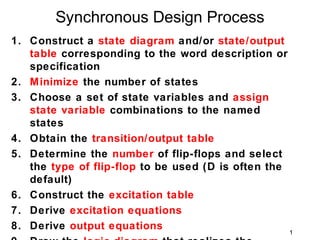
  • 1. Synchronous Design Process 1. Construct a state diagram and/or state/output table corresponding to the word description or specification 2. Minimize the number of states 3. Choose a set of state variables and assign state variable combinations to the named states 4. Obtain the transition/output table 5. Determine the number of flip-flops and select the type of flip-flop to be used (D is often the default) 6. Construct the excitation table 7. Derive excitation equations 8. Derive output equations 1
  • 2. Design a clocked synchronous state machine which detects a sequence of three or more consecutive 1’s in a string of bits coming through an input line. Mealy machine with D flip flops Moore machine with D flip flops Moore machine with JK flip flops ealy machine with D flip flops (change of encoding Assuming Mealy machine design Let the input be X and output be Z
  • 3. Obtaining the state Diagram Assume initial condition to be Z = 0 Let the initial state be represented by state A If X = 0, then output Z = 0, same state A X/Z = 1, then output Z = 0, goes to state B 1/0 0/0 A B Mealy machine A 1 B 0 Moore machine 0 0
  • 4. Obtaining the state Diagram Assume machine has moved to state B If X = 0, then output Z = 0, goes back to state A = 1, then output Z = 0, goes to state C X/Z 1/0 1/0 0/0 A B C Mealy machine 0/0 A 1 B 1 C 0 Moore machine 0 0 0 0
  • 5. Obtaining the state Diagram Assume machine has moved to state C If X = 0, then output Z = 0, goes back to state A = 1, then output Z = 1, same state C X/Z 1/0 1/0 0/0 A B C 1/1 Mealy machine 0/0 0/0 A 1 B 1 C0 1 C1 0 1 0 0 0 1 0 Moore 0 0 machin
  • 6. Obtaining the state/output table Mealy machine Moore machine State/output table State/output table State Input X State Input X Output S 0 1 S 0 1 Z A A,0 B,0 A A B 0 B A,0 C,0 B A C0 0 C A,0 C,1 C0 A C1 0 C1 A C1 1 Next State S*, Z Next State S*
  • 7. Assigning state variable to obtain Mealy machine transition/output table Moore machine Transition/output table Transition/output table State Input X State Input X Output Q1Q0 0 1 Q1Q0 0 1 Z 00 00,0 01,0 00 00 01 0 01 00,0 10,0 01 00 10 0 10 00,0 10,1 10 00 11 0 11 00 11 1 Next State Q1*Q0*, Z Encoding A = 00, B = Choosing D Next State Q1*Q0* 01 type flip flop
  • 8. Constructing the excitation table Mealy machine Moore machine Excitation/output table Excitation/output table State Input X State Input X Output Q1Q0 0 1 Q1Q0 0 1 Z 00 00,0 01,0 00 00 01 0 01 00,0 10,0 01 00 10 0 10 00,0 10,1 10 00 11 0 11 00 11 1 D1D0, Z D1D0
  • 9. Transferring onto K-maps to derive excitation equations (Mealy Machine) Excitation/ State Input X State Input X output table Q1Q0 0 1 Q1Q0 0 1 State Input X 00 0 0 00 0 1 Q1Q0 0 1 01 0 1 01 0 0 00 00,0 01,0 11 X X 11 X X 01 00,0 10,0 10 0 1 10 0 0 10 00,0 10,1 D1 D0 D1D0, Z D1 = Q0 ⋅ X + Q1⋅ X D 0 = Q1 ⋅ Q 0 ⋅ X
  • 10. Transferring onto K-maps to derive output equation (Mealy Machine) Excitation/output State Input X table Q1Q0 0 1 State Input X 00 0 0 Q1Q0 0 1 01 0 0 00 00,0 01,0 11 X X 01 00,0 10,0 10 0 1 10 00,0 10,1 Z D1D0, Z Z = Q1 ⋅ X
  • 11. Circuit (logic) diagram Mealy machine D 0 = Q1 ⋅ Q 0 ⋅ X D1 = Q0 ⋅ X + Q1⋅ Xexcitation equations Z = Q1 ⋅ X output equation X Q0 Q0' Q1 Q1' Z D0 Q0 D Q Q D1 D Q Q1 Q Clk
  • 12. Transferring onto K-maps to derive excitation equation (Moore Machine) Excitation State Input X State Input X table Q1Q0 0 1 Q1Q0 0 1 State Input X 00 0 0 00 0 1 Q1Q0 0 1 01 0 1 01 0 0 00 00 01 11 0 1 11 0 1 01 00 10 10 0 1 10 0 1 10 00 11 D1 D0 11 00 11 D1 = Q0 ⋅ X + Q1⋅ X D 0 = Q1 ⋅ X + Q 0 ⋅ X D1D0
  • 13. Transferring onto K-maps to derive output equation (Moore Machine) Excitation/output table State Input X Output Q1Q0 0 1 Z 00 00 01 0 01 00 10 0 Z = Q1⋅ Q0 10 00 11 0 11 00 11 1 D1D0
  • 14. Circuit (logic) diagramMoore machine D 0 = Q1 ⋅ X + Q 0 ⋅ X D1 = Q0 ⋅ X + Q1⋅ Xexcitation equations Z = Q1⋅ Q0 output equation X Q0 Q0' Q1 Z D0 Q0 D Q Q D1 D Q Q1 Q Clk
  • 15. Moore machine with JK flip flops Assigning state variable to obtain transition/output table Transition/output table Excitation table for State Input X Output JK flip flop Q1Q0 0 1 Z Q Q* J K 00 00 01 0 0 0 0 X 01 00 10 0 0 1 1 X 10 00 11 0 1 0 X 1 11 00 11 1 1 1 X 0 Next State Q1*Q0*
  • 16. Constructing the excitation table Transition/output table Excitation/output table State Input X Output State Input X Output Q1Q0 0 1 Z Q1Q0 0 1 Z 00 00 01 0 00 0X, 0X 0X, 1X 0 01 00 10 0 01 0X, X1 1X, X1 0 10 00 11 0 10 X1, 0X X0, 1X 0 11 00 11 1 11 X1, X1 X0, X0 1 Next State Q1*Q0* J1K1,J0K0
  • 17. Transferring onto K-maps to derive excitation equations Excitation State Input X State Input X table Q1Q0 0 1 Q1Q0 0 1 State Input X 00 0 0 00 X X Q1Q0 0 1 01 0 1 01 X X 00 0X, 0X 0X, 1X 11 X X 11 1 0 01 0X, X1 1X, X1 10 X X 10 1 0 10 X1, 0X X0, 1X J1 K1 11 X1, X1 X0, X0 J 1 = Q0 ⋅ X K1 = X J1K1,J0K0
  • 18. Transferring onto K-maps to derive excitation equations Excitation State Input X State Input X table Q1Q0 0 1 Q1Q0 0 1 State Input X 00 0 1 00 X X Q1Q0 0 1 01 X X 01 1 1 00 0X, 0X 0X, 1X 11 X X 11 1 0 01 0X, X1 1X, X1 10 0 1 10 X X 10 X1, 0X X0, 1X J0 K0 11 X1, X1 X0, X0 J0 = X K 0 = Q1 + X J1K1,J0K0
  • 19. Transferring onto K-maps to derive output equation Excitation/output table State Input X Output Q1Q0 0 1 Z 00 0X, 0X 0X, 1X 0 01 0X, X1 1X, X1 0 Z = Q1⋅ Q0 10 X1, 0X X0, 1X 0 11 X1, X1 X0, X0 1 J1K1,J0K0
  • 20. Circuit (logic) diagram excitation equations output equation J 1 = Q0 ⋅ X K1 = X Z = Q1⋅ Q0 J0 = X K 0 = Q1 + X X X' Q0 Q1' Z J0 Q0 J Q K Q K0 J1 Q1 J Q K Q Clk K1
  • 21. Assigning state variable to obtain transition/output table machine Mealy Transition/output table State Input X Change Q1Q0 0 1 of 00 00,0 01,0 Encoding A = 00 01 00,0 11,0 B = 01 11 00,0 11,1 C = 11 Next State Q1*Q0*, Z Choosing D type flip flop
  • 22. Constructing the excitation table M ealy machine Excitation/output table State Input X Q1Q0 0 1 00 00,0 01,0 01 00,0 11,0 11 00,0 11,1 D1D0, Z
  • 23. Transferring onto K-maps to derive excitation equations (Mealy Machine) Excitation/ State Input X State Input X output table Q1Q0 0 1 Q1Q0 0 1 State Input X 00 0 0 00 0 1 Q1Q0 0 1 01 0 1 01 0 1 00 00,0 01,0 11 0 1 11 0 1 01 00,0 11,0 10 X X 10 X X 11 00,0 11,1 D1 D0 D1D0, Z D1 = Q 0 ⋅ X D0 = X
  • 24. Transferring onto K-maps to derive output equation (Mealy Machine) Excitation/output State Input X table Q1Q0 0 1 State Input X 00 0 0 Q1Q0 0 1 01 0 0 00 00,0 01,0 11 0 1 01 00,0 11,0 10 X X 11 00,0 11,1 Z D1D0, Z Z = Q1 ⋅ X
  • 25. Circuit (logic) diagram Mealy machine D0 = X D1 = Q0 ⋅ X excitation equations Z = Q1 ⋅ X output equation X Z D0 Q0 D Q Q D1 D Q Q1 Q Clk
  • 26. Example 1: State Diagram • Design the FSM for the given state diagram – Graphical version of states, inputs, transitions and outputs W Z State X Y assignment Given state diagram Assigned state diagram 26
  • 27. Example 1: State Table • For each current-state, specify next-state(s) as a function of the present inputs • For each current-state, specify the output(s) as a function of the present inputs State Variables We often use Q0, Q1, Q2, etc. to acknowledge that state variables are F-F outputs 27
  • 28. Example 1: Alternate State Table • State table, alternate format emphasizing state transitions • Notation: A → Q(t) and A+ → Q(t+1), used to indicate the change in state variable needed for the desired transition Q1(t) Q0(t) → Q1(t+1) Q0(t+1) ( ) a more descriptive notation 28
  • 29. Example 1: Flip-Flop Excitation Tables • Use these tables to “move” Q to next state • Used to design the memory control CL circuit We will use the D F-F 29
  • 30. Example 1: Flip-Flop Excitation Tables • Why are we are interested in the D Flip-Flop for this design? Q(t) Q(t+1) D Operation 0 0 0 Reset 0 1 1 Set 1 0 0 Reset 1 1 1 Set We select D Flip-Flops because the D input is simply the value of Q(t+1) that we desire 30
  • 31. Example 1: Block Diagram • We need to use two D flip-flops x y (output) • The sequential circuit would look as shown (next state) Q1 D1 • We will design the CL for a 3-input, 3-output Q2 D2 circuit – CL for Output (y) – CL for Next State controls (D1 and D2) inputs = x, Q1, Q2 outputs = y, D1, D2 31
  • 32. Example 1: Truth Table • The truth table for this 3-input, 3-output circuit can be generated from the original state table • We will need to minimize each output function using Karnaugh maps, mindful of overlap 0 1 2 3 minterms 4 5 6 7 32
  • 33. Example 1: Karnaugh Maps • Minimizing each of the three outputs: A+ B+ 1 1 1 1 1 A+ = x ∙ Q1 + x ∙ Q2 B+ = x ∙ Q1 y A = Q1 and B = Q2 1 1 1 y = x ∙ Q1 + x ∙ Q2 33
  • 34. Example 1: Circuit Diagram • The circuit that results from these equations is shown below: y = x ∙ Q1 + x ∙ Q2 y = x ∙ (Q1 + Q2) A+ = x ∙ Q1 + x ∙ Q2 A+ = x ∙ (Q1 + Q2) B+ = x ∙ Q1 34
  • 35. Design: Example 2 • Given the state diagram as follows, design the sequential circuit using JK Flip-Flops D A C B state assignment A = 01 B = 10 C = 11 D = 00 35
  • 36. Design: Example 2 • Note that this is a state diagram for a Mealy machine inputs outputs 36
  • 37. Design: Example 2 • Block diagram, signal identification Input, x Sequential Logic 1-bit Circuit CP We need to determine what goes in here? 37
  • 38. Design: Example 2 • From state table, get input flip-flop function KB = Ax + A’x’ KB = Ax + A’x’ 38
  • 39. Design: Example 2 • Input flip-flop function JA Input, x A B KA x JB • Logic Diagram 1-bit KB CP x x′ B A x x B 39
  • 40. CLK QA QD QC QB 0 1 2 3 4 8 9 10 11 12 0 101 overlap M oore machine 1 1 A 1 B 0 C0 1 C1 0 0 0 0 1 0 0
  • 41. CLK QD QC QB QA LD 5 6 7 8 9 10 11 12 13 14 5 Initial Counting Reloading Loading starts
  • 42. 1110 Moore machine 1 0 1 A 1 B 1 C 1 D 0 E 0 0 0 0 0 0 1 0 0
  • 43. 43
  • 44. State Input X Output S 0 1 Z A A B 0 B A C0 0 C A C1 0 D A C1 1 Next State S* 44
  • 45. X Q0 Q1 X' Q0' D0 Q0 D Q Q D1 D Q Q1 Q D2 D Q Q2 Z Clk Q
  • 46. State Input X Output S 0 1 Z A A B 0 B A C0 0 C0 A C1 0 C1 A C1 1 Next State S* 46