Factors and Elements of Airport Lighting Systems
•Download as PPTX, PDF•
109 likes•45,883 views

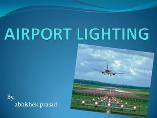
The document discusses several key factors regarding airport lighting, including different types of lights used for various purposes like approach lighting, runway lighting, taxiway lighting, and threshold lighting. It explains that airport lighting must be properly installed and maintained to guide pilots during night operations or low visibility conditions. Different lighting systems and patterns are used depending on the airport classification and level of air traffic. Standardization of airport lighting helps pilots navigate unfamiliar airports safely.

Recommended
More Related Content
What's hot
What's hot (20)
Similar to Factors and Elements of Airport Lighting Systems
Similar to Factors and Elements of Airport Lighting Systems (20)
More from Abhishek Prasad
Factors and Elements of Airport Lighting Systems
- 1. By, abhishek prasad
- 2. FACTORS AFFECTING AIRPORT LIGHTING: Airport classification Amount of traffic Availability of power Nature of aircraft using the airport Type of night operation plans Type of landing surfaces provided Weather condition, etc.
- 3. (contd.) To achieve uniformity and to guide pilots for unfamiliar airports, colours and general arrangement of airport lights are standardized. Airport lights are kept clean, well-maintained, checked regularly for faulty bulbs and replacement. Tough and laborious job, major airport contains 30,000 lights Provision of emergency power supplies, which can take over in seconds in case of any power failure.
- 4. ELEMENTS OF AIRPORT LIGHTING: Airport beacon Approach lighting Apron and hangar lighting Boundary lighting Lighting of landing direction indicator Lighting of wind direction indicator Runway lighting Taxiway lighting Threshold lighting
- 5. 1) AIRPORT BEACON: Beacon- strong beam of light- used to indicate any geographical location- situated slightly above the horizontal- rotated to produce flashing light to an observer. It gives out white and green flashes in the horizontal directions 180◦ apart. Flashes are visible for the pilot from any direction of approach and it indicates the approximate situation of an airport equipped for the night operations. Rotates at six revolutions per minute- mounted at top of terminal building or hangar.
- 6. (contd.) Obstruction not cleared yet- then separate tower is provided for installation of rotating beacon. Code beacon- indicates light provided sufficiently high to clear all obstructions. It consists of two 500 watts bulb with green colour screen. Continuously flashes a Morse code signal designating the airport.
- 9. APPROACH LIGHTING: Before runway begins- sequence of high-intensity lighting arrangement for a length of 900m. Helps pilots to check if the aircraft is centered correctly of not. Gives way to touchdown zone lights from threshold of the runway. Normally mounted on pedestals-varying heights-to accommodate any irregularities in ground- ensuring the lights themselves are in level.
- 10. (contd.) Arrangements adopted for approach lightings: 1) Calvert system 2) ICAO system
- 11. 1) Calvert system: Widely used in Europe and other parts of the world. Developed by E.S.Calvert in Great Britain. In this, there are six transverse rows of lights of variable length placed at a c/c distance of 15om. In this, the roll guidance is principally provided by the transverse rows of lights.
- 13. 2) ICAO system: Known as centre-line configuration. In this, there is only one crossbar 300m from the threshold. In this, the roll guidance is provided by bars 4.2m in length, placed at 30m c/c on the extended centre-line of the runway and a single crossbar 300m from the threshold. The 4.2m long bars consists of 5 closely spaced lights to give the effect of continuous bar of light.
- 16. APRON AND HANGAR LIGHTING: These areas for are flood lit for the convenience in servicing and loading Flood-lighting system: constitues a projector designed to be arranged to illuminate a surface. Mounted such a way that they do not cause glare in the eyes of the pilots, passengers and service personnel. Recommendation: flood lights should be placed at a height of not less than 12m above the pavement.
- 17. BOUNDARY LIGHTING: Entire boundary of the airfield is provided with lights at a c/c distance of about 90m with height of about 75cm from the ground. If fence is provided along the boundary, then these lights should be placed inside the fence at a distance of about 3m. For indicating hazardous approach, the boundary lights are provided with red marker lights
- 19. LIGHTING OF LANDING DIRECTION INDICATOR: The landing direction indicator is illuminated with suitable lighting arrangement so that the airport can be used at night also.
- 21. LIGHTING OF WIND DIRECTION INDICATOR: The wind direction indicator is illuminated by four 200 watts angle reflectors placed 1.8m above the top of the cone for providing a continuous lighting at any position of the cone. This arrangement grants the use of wind direction indicator at night and during bad weathers.
- 22. RUNWAY LIGHTING: After crossing the threshold, the pilot must complete a touchdown and roll out on the runway. The planning of runway lighting is carried out in such a way that the pilot gets enough information on alignment, lateral displacement, roll and distance. The lights are so arranged so that they form a visual pattern which the pilot can interpret easily. During night landings, flood lights were used in olden days. But now runway edge lights are adopted.
- 23. (contd.) Narrow gauge pattern- the most precise runway alignment which is widely used. It makes use of centre-line and touch down zone lights for operations in very poor visibility. Black hole effect: As the pilot crosses the threshold, and continues to look along the centre-line, the principal source of guidance, namely, the edge lights has moved far to each side in the peripheral vision. As a result, the central area appears black and the pilot is virtually flying blind for the peripheral reference information.
- 24. (contd.) This can be eliminated by adopting the narrow gauge pattern of the runway lighting, the central portion gets illuminated and the black hole effect is partly eliminated. The narrow gauge pattern forms a channel of light of 18m width up to 1140m from the threshold and beyond this distance, the closely spaced lights are placed along the centre-line of the runway extending up to the other end of the runway.
- 25. (contd.) All the lights provided on the runway are white in colour and of flush type, i.e. they do not protrude more than 1cm above the surface of pavement. The runway edge lights are of elevated type and they are white colour except for the last 400m if an instrument runway facing the pilot which are of yellow colour to indicte a caution zone.
- 28. TAXIWAY LIGHTING: The pilots have to manoeuvre the aircrafts on a system of taxiways to and from the terminal and hangar areas either after landing or on the way to take off The taxiway system is much complicated on large airports and therefore it is necessary to provide adequate lighting at night and at daytime when the visibility is very poor.
- 29. Design considerations to be applied to the visual aids for the taxiways: For normal exits- centreline terminated at the edge of the runway. At taxiway intersections, the lights continue across the intersection. They are placed at a distance of 6m to 7.5m along the straight length and 3m to 3.6m along the curves. The complete route from the runway to the apron should be easily identified. The edge lights should not extend more than 75cm above the pavement surface.
- 30. (contd.) The exits from the runways should be so lighted that the pilots are able to locate the exits 360m to 400m ahead of the point of turn. The intersection of taxiways and runways-taxiway crossings should be clearly marked. The lights on the tangent portion are placed not more than 60m apart and the distance from the edge along the curves and the intersections to facilitate easy identification. The spacing varies from 6m for curve of radius 4.5m to 60m for a curve of 300m.
- 31. (contd.) There should be adequate guidance along the taxiway. The taxiway edge lights are blue and the taxiway centre lights are green. The taxiway should be clearly identified so that they are not confused with the runways.
- 35. THRESHOLD LIGHTING: Identification of threshold- a major factor for decision of the pilot to land or not to land For this reason, the region near the threshold is given with special lighting treatment. At large airports: threshold is identified by a complete line of green lights extending across the entire width of the runway. They must be of semi-flash type, i.e. protruding not more than 12cm above the surface.
- 36. (contd.) At small airports, the threshold is identified by four lights on each side of the threshold. They can be of elevated type, i.e. protruding more than 12cm above the surface. The threshold lights in the direction if landing are green and in the opposite direction, they are red to indicated the end of the runway.