
Recomendados
Más contenido relacionado
Similar a PPP_Multilink.pdf
Similar a PPP_Multilink.pdf (20)
Último
Último (20)
PPP_Multilink.pdf
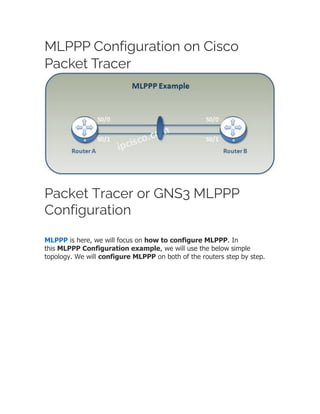
- 1. MLPPP Configuration on Cisco Packet Tracer Packet Tracer or GNS3 MLPPP Configuration MLPPP is here, we will focus on how to configure MLPPP. In this MLPPP Configuration example, we will use the below simple topology. We will configure MLPPP on both of the routers step by step.
- 2. In Multilink PPP Configuration example, we will do the below configurations: 1. Firstly we will create MLPPP Bundle Interface and assign IP Address to this interface. 2. Then, we will assign the physical interfaces under MLPPP bundle. 3. Lastly, we will verify our MLPPP configuration. Now, let’s start our configuration.
- 3. Creating MLPPP Bundle Firstly, we will create MLPPP Bundle, Logical Interface. We will set the encapsulation as PPP and we will assign an IP address to the logical interface. Router1(config)# interface multilink 1 Router1(config-if)# encapsulation ppp Router1(config-if)# ip addres 10.0.0.1 255.255.255.0 Router1(config-if)# exit Router2(config)# interface multilink 1 Router2(config-if)# encapsulation ppp Router2(config-if)# ip addres 10.0.0.2 255.255.255.0 Router2(config-if)# exit Configuring MLPPP Bundle Members We will assign each physical serial interface under the MLPPP bundle. To do this, firstly we will remove the interface ip address with “no ip address” command and then we will determine the encapsulation type as PPP. After that, we will enable MLPPP with “ppp multilink” commands and then we will assign the physical interfaces to the bundle with “ppp multilink group” command. Router1(config)# interface serial 0/0 Router1(config-if)# no ip address Router1(config-if)# encapsulation ppp
- 4. Router1(config-if)# ppp multilink Router1(config-if)# ppp multilink group 1 Router1(config-if)# no shutdown Router1(config-if)# exit