SlideShare una empresa de Scribd logo
1 de 27
Descargar para leer sin conexión
Broadband System - J

                           Satellites are spaced every
                            2nd degrees above earth


"C" Band
Toward satellite 6.0 GHz                                 "L" Band
Toward earth 4.0 GHz                                     Toward satellite 14.0 GHz
                                                         Toward earth 12.0 GHz


                TV
            TRANSMITTER
                           Headend

                                       Cable area
                                                                                     1
                           HFC System Distortions
Distortions in a Broadband System.


In this section we will learn how to calculate the distortions
in a Broadband System. This presentation will help
understand, why the system performs better closer to the
headend and get worst, toward the end of the system.


                                                             2
Distortions in a Broadband System.


Here are the distortions we will covering in this section;
•Distortion of second order.
•Distortion of third order
•Cross modulation.
•Composite third order, CTB.
•Composite second order, CSO.
•Noise.
•Hum.


                                                             3
Distortions in a Broadband System.


Formulas for calculating distortions on a
    HFC, Broadband system, CATV.


                                            4
Distortions in a Broadband System.

After you have decided the number of customers per NODE, you’ll need to
determinate at what level you system will operate. This is done by the
following:
•Determinate the optical level (light level) at the NODE, this will give you
distortion level at the NODE.
•You then need to determinate the length of the coaxial system. (how
many amp. In cascade)
•You will have to determinate the operating level of the amplifiers.
•Then you can calculate the distortion of each leg of the system.


   Light level        JXP
      dBm                                   0 dBm             1.0dBm
                                            53.0 dB           54.0 dB C/N
                    P. S.                   -65.0dB           -65.0 dB CTB
                                 RF level
                                  dBmV      -65.0dB           -65.0 dB CSO

                                                                             5
Distortion in a Broadband System.


                            Attached are the
                                technical
                           specifications of a
                            870 MHz optical
                                  NODE


                                                 6
Noise Distortion in a Broadband System.


 Noise distortion for one RF amplifier:
 Formula is:
 C-N ratio = Input signal (dBmV) + 59.2 – (Noise Figure of each amplifier).
 It is always a good practice to add one (1) dB to the noise figure given by
 manufacture, due of the cable equalizer that will be installed at their input.
          16 dBmV
            input                        59.2 + 16 - (10+1)=64.2   dB C/N


Remark:             10 dB Noise Figure

59.2 dB is the thermal noise for: 4.2 MHz of bandwidth on a CATV amplifier.
                                                                            7
Noise Distortion in a Broadband System.


                            Attached are the technical
                              specifications of a 870
                                MHz RF amplifier


                                                 8
Distortion in a Broadband System.


                       All distortions.
You need to calculate the distortions of the CASCADE of the RF
amplifiers and then married (add) these distortions to the Optical
NODE, to get the actual system’s distortions.


      NODE
                    CASCADE of RF amplifiers


              Then add the NODE distortions.
                                                               9
Distortion in a Broadband System.

                        Carrier to Noise

For a cascade of amplifier, where all of the amplifiers operate at
the same level (input and output)


                    C/Ns= C/N - log N
                                            10
The formula is:


N = Number of amplifier in the cascade.


Formula for different operating level:

                              -C/N1       -C/N2            -C/N n
     C/Ns= -10log10            10           10              10
                         10           +10         +...10
                                                                    10
Distortion in a Broadband System.


                             Carrier to Noise

         To sum differing Carrier to Noise ratios:

                                       10 * 10 log10 2         10 * 10 log10 3
                   C-N


   10 * 10 log10 ( -C/N 1 + -C/N 2 )
                    10 10    10 10
                                         10 * 10 log10 ( -C/N 1 + -C/N 2 )
                                                          10 10    10 10
To do this calculation, things you need to know are; the distortion
(Carrier to Noise or Noise figure) of each amplifier, their spacing at
***MHz and their operating level, so you’ll know their input level.
                                                                                 11
Distortion in a Broadband System.


                                    Carrier to CSO
                 CSO                15 * 10 log10 2             15 * 10 log10 3


15 * 10 log10 ( -CTB 1 + -CTB 2 )
                 10 10    10 10

                        15 * 10 log10 ( -CTB 1 + -CTB 2 )
                                         10 10    10 10
                                                      15 * 10 log10 ( -CTB 1 + -CTB 2 )
Composite Second Order:                                                10 10    10 10
•Is always given as negative number.
•For each 1 dB in change of output level, the change in CSO will be 1 dB.
•Each time we double the cascade, CSO distortion get worse by 3.01 dB.
                                                                                   12
Distortion in a Broadband System.


                                 CTB & X-Modulation

                      Xmod.               20log10 2                 20log10 3
                      CTB.


   20 * 10 log10 ( -XM 1        -XM 2 )
                            +
                    20 10        20 10
                                 20 * 10 log10 ( -XM 1        -XM 2 )
                                                          +
                                                  20 10        20 10
Crossmodulation & CTB:                                20 * 10 log10 ( -XM 1        -XM 2 )
                                                                               +
                                                                       20 10        20 10
•Is always given as negative number.
•For each dB change in output level, the change in CTB and Xmod. is 2.0 dB.
•Each time we double the cascade, CTB and Xmod. get worse by 6.02 dB.
                                                                                       13
Distortion in a Broadband System.


                         CTB & XModulation

For a cascade of amplifiers, when they operates at the same output level,
here is the formulas to calculate the CTB and Cross Modulation
distortion.


The formula is:


                  CTB’s or Xmod’s - 20 log10 N

N = Number of amplifier in the cascade.


                                                                     14
Distortion in a Broadband System.


                                    HUM
Hum can be measured in dB or in percentage (%). Since hum is often
caused by a defective piece of equipment, HUM is usually not cascade
distortion dependant. HUM is generally measured on a CW channel (channel
without modulation).
If your HUM distortion is measured in dB, the formula below permits to
transfer dB HUM to HUM percentage (%).
The formula below shows the calculation of a -60 dB HUM distortion to %
HUM.
                        % = ( R / R) * 100
                             10 20
                         % = ( 60 ) *100
                              10 20
                         % = ( 10   3   ) * 100
                         % = .001 X 100 = 0.1%                     15
Distortion in a Broadband System.


                             All Distortions measurements.
           Cascade (N)         10*log (N)    15*log (N)     20*log (N)
                         1     0.00          0.00                  0.00
                         2     3.01          4.52                  6.02
                         3     4.77          7.16                  9.54
                         4     6.02          9.03                  12.04
                         5     6.99          10.48                 13.98
                         6     7.78          11.67                 15.56
                         7     8.45          12.68                 16.90
                         8     9.03          13.55                 18.06
                         9     9.54          14.31                 19.08
                         10    10.00         15.00                 20.00
                         11    10.41         15.62                 20.83
                         12    10.79         16.19                 21.58
                         13    11.17         16.71                 22.28
                         14    11.46         17.19                 22.92

Distortions calculation for a series of amplifiers, when all amplifier have the same
output level. This calculate C/N, CSO and CTB of a cascade of amplifiers.
At the 5th amplifier C/N will be: 6.99 dB, CSO will be: 10.48 dB and CTB will be:
13.98 dB worst than the first amplifier of the cascade,                       16
Distortions in a Broadband System.

                   CTB, Xmod with different Operating Level.
                     dB   0.00   0.10    0.20   0.30   0.40   0.50   0.60   0.70   0.80   0.90
                      0   6.02   5.97    5.92   5.87   5.82   5.77   5.73   5.68   5.63   5.58
                      1   5.53   5.49    5.44   5.39   5.35   5.30   5.26   5.21   5.17   5.12
                      2   5.08   5.03    4.99   4.95   4.90   4.86   4.82   4.78   4.73   4.69
                      3   4.65   4.61    4.57   4.53   4.49   4.45   4.41   4.37   4.33   4.29
                      4   4.25   4.21    4.17   4.13   4.10   4.06   4.02   3.98   3.95   3.91
                      5   3.88   3.84    3.80   3.77   3.73   3.70   3.66   3.63   3.60   3.56
                      6   3.53   3.50    3.46   3.43   3.40   3.36   3.33   3.30   3.27   3.24
                      7   3.21   3.18    3.15   3.12   3.09   3.06   3.03   3.00   2.97   2.94
                      8   2.91   2.88    2.85   2.83   2.80   2.77   2.74   2.72   2.69   2.66
                      9   2.64   2.61    2.59   2.56   2.53   2.51   2.48   2.46   2.44   2.41
                     10   2.39   2.36    2.34   2.32   2.29   2.27   2.25   2.22   2.20   2.18
                     11   2.16   2.13    2.11   2.09   2.07   2.05   2.03   2.01   1.99   1.97
                     12   1.95   1.93    1.91   1.89   1.87   1.85   1.83   1.81   1.79   1.77
                     13   1.75   1.74    1.72   1.70   1.68   1.67   1.65   1.63   1.61   1.60
                     14   1.58   1.56    1.55   1.53   1.51   1.50   1.48   1.47   1.45   1.44
                     15   1.42   1.41    1.39   1.38   1.36   1.35   1.33   1.32   1.31   1.29
                     16   1.28   1.26    1.25   1.24   1.22   1.21   1.20   1.19   1.17   1.16
                     17   1.25   1.14    1.12   1.11   1.10   1.09   1.08   1.06   1.05   1.04
                     18   1.03   1.02    1.01   1.00   0.99   0.98   0.96   0.95   0.94   0.93
                     19   0.92   0.91    0.90   0.89   0.88   0.87   0.86   0.86   0.85   0.84
                     20   0.82   0.80    0.78   0.76   0.75   0.74   0.72   0.70   0.69   0.68

            You must removed the reading to the lowest of the two levels.
Trunk Distortion = 71.45 dB – Bridger Distortion = 61.44 dB or 10.20 dB diff. = 2.34 dB
                                        61.44 – 2.34 = 59.10 dB                                  17
Distortions in a Broadband System.


                2nd Order, C/N with different Operating Level.
                   dB   0.00   0.10    0.20   0.30   0.40   0.50   0.60   0.70   0.80   0.90
                    0   3.01   2.96    2.91   2.86   2.81   2.77   2.72   2.67   2.63   2.58
                    1   2.54   2.50    2.45   2.41   2.37   2.32   2.28   2.24   2.20   2.16
                    2   2.12   2.09    2.05   2.01   1.97   1.94   1.90   1.87   1.83   1.80
                    3   1.76   1.73    1.70   1.67   1.63   1.60   1.57   1.54   1.51   1.48
                    4   1.46   1.43    1.40   1.37   1.35   1.32   1.29   1.27   1.24   1.22
                    5   1.19   1.17    1.15   1.12   1.10   1.08   1.06   1.04   1.01   0.99
                    6   0.97   0.95    0.93   0.91   0.90   0.88   0.86   0.84   0.82   0.81
                    7   0.97   0.77    0.76   0.74   0.73   0.71   0.70   0.68   0.67   0.65
                    8   0.64   0.63    0.61   0.60   0.59   0.57   0.56   0.55   0.54   0.53
                    9   0.51   0.50    0.49   0.48   0.47   0.46   0.45   0.44   0.43   0.42
                   10   0.41   0.40    0.40   0.39   0.38   0.37   0.36   0.35   0.35   0.34
                   11   0.33   0.32    0.32   0.31   0.30   0.30   0.29   0.28   0.28   0.27
                   12   0.27   0.26    0.25   0.25   0.24   0.24   0.23   0.23   0.22   0.22
                   13   0.21   0.21    0.20   0.20   0.19   0.19   0.19   0.18   0.18   0.17
                   14   0.17   0.17    0.16   0.16   0.15   0.15   0.15   0.14   0.14   0.14
                   15   0.14   0.13    0.13   0.13   0.12   0.12   0.12   0.12   0.11   0.11
                   16   0.11   0.11    0.10   0.10   0.10   0.10   0.09   0.09   0.09   0.09
                   17   0.09   0.08    0.08   0.08   0.08   0.08   0.07   0.07   0.07   0.07
                   18   0.07   0.07    0.07   0.06   0.06   0.06   0.06   0.06   0.06   0.06
                   19   0.05   0.05    0.05   0.05   0.05   0.05   0.05   0.05   0.05   0.04
                   20   0.04   0.04    0.04   0.04   0.04   0.04   0.04   0.04   0.04   0.04

          You must removed the reading to the lowest of the two levels.
Trunk distortion = 52.09 dB – Bridger distortion = 48.23dB or = 3.86 diff. = (1.48 dB)
                                      48.23 – 1.48 = 46.75 dB                                  18
Distortions in a Broadband System.
                        Operating an RF Amplifier at Different Level.
                                                                                                                                    870
                                                                                                                                    MHz

                                                                                     870
                                                     50                              MHz                    50
                                                    MHz                                                    MHz


                                                                                                                                                     to
                                                                                                                                                   status
                                                                                                                                                  monitoring            -20 dB
           870     50
           MHz    MHz


                    40
                   MHz 5
                                                                                                                                                        JXP                                       RF/
                                                                                                                                                                                        RF
                       MHz                                                                                                                                                                        AC                870
                                                                                                                                                                                             AC
                                                                                                                                                                                                                    MHz

                                               -20 dB
                                                                                                                                                                                                               50
                                                                                                                                                                                                              MHz
                             RF/                                  EQ   JXP              BODE         BRD         JXP                                                                                     5 40
                             AC           RF                                                                                                                                                            MHz MHz
                                   AC


                                                                                           ADU                   JXP
                                                                          Manual
                                                                           Gain
                                                         5 40             Control                                                                              -20 dB
                                                        MHz MHz


                                                                                                  5   40
                                                                                                                                                  ICS   JXP
                                                                                                 MHz MHz
                                                                                                                          from


                                                                                                                                                                                 fuse
                                                                                                                         status
                                                                                                                       monitoring
                                                                   -20 dB
                                                                                                                         -16 dB
                                   fuse


                                                                                                                                           ICS
                                                                                EQ          JXP                    JXP                    Drive

                                                                                 24 Vdc
                                                                      to
                                                                    status        vcc
                                                                                             Power
                                                                   monitoring                Supply
                                                        90 / 60
                                                         Vac                         fuse


If we increase the input of this amplifier, we will                                                                                       If we get this amplifier to works at +45.0 dBmV and his
increase the Carrier to Noise of the amplifier. For                                                                                       distortions level are –75.0 for CTB, -74.0 dB for CSO,
                                                                                                                                                                           CTB,             CSO,
every increase of 1.0 dB at the input, the Carrier to                                                                                     and if we increase his output to +47.0 dBmV, the CTB
                                                                                                                                                                                   dBmV,
Noise of the amplifier will better itself by 1.0 dB.                                                                                      level will now be –71.0 dB and the CSO will now be –
Let say this amplifier has 10.0 dB of Noise and you                                                                                       72.0 dB.
hit the amplifier by a level of +10.0 dBmV, his C/N                                                                                        For every increase of 1.0 dB at the output of the
will be 59+10-10=59.0 dB C/N. If you hit the same
        59+10-                                                                                                                            amplifier, the CTB will get worse by 2.0 dB and the
amplifier at +12.0 dBmV, his C/N will now be 59+12-
                                             59+12-                                                                                       CSO will get worse by 1.0 dB
10=61.0 dB C/N                                                                                                                                                                                                            19
Distortions in a Broadband System.


                       Distortion on a RF Section of a HFC System.

                 1         2     3           4         5           6           7          8

                                  Distortion Calculation:                 Cascade Specification:
  Input; +12 dBmV
                                  CTB = 8 x 20log10 = 18.6 dB             C/N = 60.0 - 9.03 = 50.97 dB
  Noise Fig. = 11 dB
                                  CSO = 8 x15log10 = 13.54                CTB = -77.0 - 18.6 = 58.4 dB
  Output = +45 dBmV
                                  C/N = 8 x 10log10 = 9.03                CSO = -76.0 - 62.46 = 62.46 dB
  CTB = -77.0 dB
  CSO = -76.0 dB
                               Changing the operation level:
Amplifier specification:
                               Since at the end of this cascade the distortions are good, we could lower
                                                                                               could
C/N = 59+12-11 = 60.0 dB
      59+12-                   the output of this cascade by 1.0 dB, it input would now be 12.0 –1.0 = 11.0
CTB = -77.0 dB                 dBmV, then it output would then be + 44.0 dB, then the cascade would  would
                               have the following distortions:
CSO = -76.0 dB
                               C/N = 50.97 – 1.0 = 49.97 dB
                               CTB = 58.4 + 2.0 = 60.4 dB
                               CSO = 62.46 + 1.0 = 63.46 dB
                                                                                                     20
Distortions in a Broadband System.


                    Distortion on a RF Section of a HFC System.


  NODE             1       2          3           4          5             6         7          8

                                                                           Cascade Specification:
NODE Distortion:
                                                                           C/N = 60.0 - 9.03 = 50.97 dB
C/N = 53.0 dB
                                                                           CTB = -77.0 - 18.6 = 58.4 dB
CTB = - 65.0 dB                                                            CSO = -76.0 - 62.46 = 62.46 dB
CSO = -64.0 dB
                           Overall Specification:
                           C/N = 53.0 – 50.97 or 50.97 – 2.03 = 48.94 dB
                           CTB = 65.0 – 58.4 or 58.4 – 3.33 = 55.07 dB
                           CSO = 64.0 – 62.46 or 62.46 –2.32 = 60.14 dB


        Remember the minimum distortion expected at each customer are;
                   C/N = 48.0 dB,     CTB = -51.0 dB,            CSO = -51.0 dB
                                                                                                     21
Distortions in a Broadband System.


How distortions are measured on a HFC system.

 Last Active
 on System

               30


                     Variable
                    Bandpass                  Spectrum
                      Filter                  Analyzer

                                Variable RF
                                Attenuator


                                                         22
Distortions in a Broadband System.

 Distortion Measurement Calculated using a Spreadsheet.
                                           HFC system distortion
                    Name of System : ***
                       System Freq. :      870      MHz 77 ch. CW and 320 MHz Data @ 6 dB Lower than Analog ch.
                                                                                                                  Maximum
                                         Single RF Amplifier performance
                                                                                                                    gain
                       Type of amp. : MB87S E-GaAs                  Max Gain       45         dB
                     Amp. Noise Fig. :     12.0     dB @ 52 MHz
                                          50 MHz     / 550 MHz /    870 MHz
                                                                                                                  Reserve
    Operating            Oper. Level :      36              43         48      dBmV           O utput No 1 & 2

      gain                                                           with a TV signal at 865.25 MHz                gain
                         Oper. Gain :       38      dB                    Re serve . Gain :        7    dB gain
                               Single    amp. Distortion                            Input next Amplifier :
                               CTB :      -75.00 dB For 79 ch. and 320 MHz data        10.00 dBmV
                               CSO :      -72.00 dB      "                with a TV signal at 745,25 MHz
                                C/N :     57.00 dB       "

Number of Amp.                            Coaxial System performance

  In cascade                                                5       Number of amp. In cascade

                                                                    Output No 2 & 3
                                                 C TB :  -61.02 dB For 77 ch. and 200 MHz data
  RF amp.
                                                 CSO : -61.52 dB        "          "
 distortion                                      C / N : 50.01 dB       "          "
                                                                                                                     HFC
                                          Complete system performance                                             distortion
                 Input dBm;                       Amplifier Cascade

                   0.0      Opt. Rx fiber                   5           With 2 outputs same leve l

                                                          Optical   Complete
                                                          System     System
                                              CTB : -65.00 dB -56.76 For 79 ch. and 320 MHz data
                                              CSO : -62.00 dB -58.74      "           "
                                              C / N : 52.00 dB 47.88      "           "
                                                                                                                               23
                                                                                     coaxial/calcul/dist77-750
Distortions in a Broadband System.


Distortion Measurement Accepted at all the Customer.
                                6.0 MHz
         0


        -10


                                                 Signal-to-
        -20                                 Interference limites

        -30


     dB -40


        -50

            C   C   CTB C   C
            S   S       S   S
        -60 O   O       O   O


        -70
                            3.59 MHz                          24
                                  4.5 MHz
Test!


        25
•What is the best Carrier to Noise possible for a 6 MHz RF signal?
•______________________________________________________________
•A + 10 dBmV input for an amp. with 11.5 dB Noise Fig. What is his C/N?
•_______________________________________________________________
•A amp. has –65.0 dB CTB at 46.0 dBmV output, what is the CTB for a 42.0 dBmV?
•_______________________________________________________________
•What does CSO stand for?
•_______________________________________________________________
•Which of the two distortions, CTB or CSO degrade faster in a HFC system?
•_______________________________________________________________
•First amp. Has –74.0 dB CTB, what will be the CTB after 6 amps?
•_______________________________________________________________
•What is the minimum AC voltage for a modern amplifier?
•_______________________________________________________________
•What is the maximum amp. Cascade on a modern HFC system>
•________________________________________________________________
                                                                            26
27

Más contenido relacionado

La actualidad más candente

SAT-202 Vehicle Tracking
SAT-202 Vehicle TrackingSAT-202 Vehicle Tracking
SAT-202 Vehicle TrackingHarvey Ellis
 
Relationships Among EVM, BER and SNR + WiFi minimum SNR consideration
Relationships Among EVM, BER and SNR + WiFi minimum SNR considerationRelationships Among EVM, BER and SNR + WiFi minimum SNR consideration
Relationships Among EVM, BER and SNR + WiFi minimum SNR considerationPei-Che Chang
 
Cambium networks pmp_450_access_point_specification
Cambium networks pmp_450_access_point_specificationCambium networks pmp_450_access_point_specification
Cambium networks pmp_450_access_point_specificationAdvantec Distribution
 
Cambium networks ptp_200_(4.9_g_hz)_specification
Cambium networks ptp_200_(4.9_g_hz)_specificationCambium networks ptp_200_(4.9_g_hz)_specification
Cambium networks ptp_200_(4.9_g_hz)_specificationAdvantec Distribution
 
Cable Infrastructure Evolution
Cable Infrastructure EvolutionCable Infrastructure Evolution
Cable Infrastructure EvolutionXiaolin Lu
 
Passive component z versus freq
Passive component z versus freqPassive component z versus freq
Passive component z versus freqPei-Che Chang
 
Duplexer
DuplexerDuplexer
Duplexerescola
 
iCAT C600 Permanent Link Test with iCAT Cat6 Jack
iCAT C600 Permanent Link Test with iCAT Cat6 JackiCAT C600 Permanent Link Test with iCAT Cat6 Jack
iCAT C600 Permanent Link Test with iCAT Cat6 JackJulie Fletcher
 
Ave - TV receiver (PAL - D circiut main)
Ave - TV receiver (PAL - D circiut main)Ave - TV receiver (PAL - D circiut main)
Ave - TV receiver (PAL - D circiut main)prathik
 
Cambium networks ptp_230_specification
Cambium networks ptp_230_specificationCambium networks ptp_230_specification
Cambium networks ptp_230_specificationAdvantec Distribution
 
Vlsi implementation ofdm
Vlsi implementation ofdmVlsi implementation ofdm
Vlsi implementation ofdmManas Verma
 
802.11ac WIFI Fundamentals
802.11ac WIFI Fundamentals802.11ac WIFI Fundamentals
802.11ac WIFI Fundamentalscriterion123
 

La actualidad más candente (17)

SAT-202 Vehicle Tracking
SAT-202 Vehicle TrackingSAT-202 Vehicle Tracking
SAT-202 Vehicle Tracking
 
Hw7 solution
Hw7   solutionHw7   solution
Hw7 solution
 
Relationships Among EVM, BER and SNR + WiFi minimum SNR consideration
Relationships Among EVM, BER and SNR + WiFi minimum SNR considerationRelationships Among EVM, BER and SNR + WiFi minimum SNR consideration
Relationships Among EVM, BER and SNR + WiFi minimum SNR consideration
 
Cambium networks pmp_450_access_point_specification
Cambium networks pmp_450_access_point_specificationCambium networks pmp_450_access_point_specification
Cambium networks pmp_450_access_point_specification
 
Mti
MtiMti
Mti
 
Hfc k understanding bi-direction
Hfc k understanding bi-directionHfc k understanding bi-direction
Hfc k understanding bi-direction
 
Cambium networks ptp_200_(4.9_g_hz)_specification
Cambium networks ptp_200_(4.9_g_hz)_specificationCambium networks ptp_200_(4.9_g_hz)_specification
Cambium networks ptp_200_(4.9_g_hz)_specification
 
Cable Infrastructure Evolution
Cable Infrastructure EvolutionCable Infrastructure Evolution
Cable Infrastructure Evolution
 
Passive component z versus freq
Passive component z versus freqPassive component z versus freq
Passive component z versus freq
 
Duplexer
DuplexerDuplexer
Duplexer
 
Kramer PT-103V
Kramer PT-103VKramer PT-103V
Kramer PT-103V
 
iCAT C600 Permanent Link Test with iCAT Cat6 Jack
iCAT C600 Permanent Link Test with iCAT Cat6 JackiCAT C600 Permanent Link Test with iCAT Cat6 Jack
iCAT C600 Permanent Link Test with iCAT Cat6 Jack
 
Ave - TV receiver (PAL - D circiut main)
Ave - TV receiver (PAL - D circiut main)Ave - TV receiver (PAL - D circiut main)
Ave - TV receiver (PAL - D circiut main)
 
Cambium networks ptp_230_specification
Cambium networks ptp_230_specificationCambium networks ptp_230_specification
Cambium networks ptp_230_specification
 
Kramer 104-LN
Kramer 104-LNKramer 104-LN
Kramer 104-LN
 
Vlsi implementation ofdm
Vlsi implementation ofdmVlsi implementation ofdm
Vlsi implementation ofdm
 
802.11ac WIFI Fundamentals
802.11ac WIFI Fundamentals802.11ac WIFI Fundamentals
802.11ac WIFI Fundamentals
 

Destacado

Inria - Connect 3
Inria - Connect 3Inria - Connect 3
Inria - Connect 3Inria
 
Semih üStüN GöZtepe Kart Sunumu 04 02 10 V01
Semih üStüN  GöZtepe Kart Sunumu 04 02 10 V01Semih üStüN  GöZtepe Kart Sunumu 04 02 10 V01
Semih üStüN GöZtepe Kart Sunumu 04 02 10 V01asd
 
Lina Marcela Salgado Ramos
Lina Marcela Salgado RamosLina Marcela Salgado Ramos
Lina Marcela Salgado Ramosguest29caee
 
Wright Canvas Art & Fine Art Photographs
Wright Canvas Art & Fine Art PhotographsWright Canvas Art & Fine Art Photographs
Wright Canvas Art & Fine Art PhotographsPBWright
 
Training Art And Craft Brosura
Training   Art And Craft BrosuraTraining   Art And Craft Brosura
Training Art And Craft Brosurahartdevelopment
 
Inria - 2012 Annual Report: Digital Technology, the social dimension
Inria - 2012 Annual Report: Digital Technology, the social dimensionInria - 2012 Annual Report: Digital Technology, the social dimension
Inria - 2012 Annual Report: Digital Technology, the social dimensionInria
 
Premium Inspection Report
Premium Inspection ReportPremium Inspection Report
Premium Inspection ReportTom Rosenberger
 
Inria - leaflet of research centre Nancy - Grand Est
Inria - leaflet of research centre Nancy - Grand EstInria - leaflet of research centre Nancy - Grand Est
Inria - leaflet of research centre Nancy - Grand EstInria
 
Градиент Опека
Градиент ОпекаГрадиент Опека
Градиент ОпекаPaul Serikov
 
Geoconda muñoz beneficios web 2.0
Geoconda muñoz beneficios web 2.0Geoconda muñoz beneficios web 2.0
Geoconda muñoz beneficios web 2.0YOGISS Muñoz
 
CLOUD COMPUTING
CLOUD COMPUTINGCLOUD COMPUTING
CLOUD COMPUTINGdasaa
 
Ingles8 Publishing
Ingles8 PublishingIngles8 Publishing
Ingles8 Publishingcarlos214
 
Формула «создания» доходного специалиста
Формула «создания» доходного специалистаФормула «создания» доходного специалиста
Формула «создания» доходного специалистаSalesDog
 
Inria - 2011 annual report
Inria - 2011 annual reportInria - 2011 annual report
Inria - 2011 annual reportInria
 
Technology And Student Achievement
Technology And Student AchievementTechnology And Student Achievement
Technology And Student Achievementjblikre
 
Benefit Associates, Inc. - About Us
Benefit Associates, Inc. - About UsBenefit Associates, Inc. - About Us
Benefit Associates, Inc. - About Uskellyanneban
 

Destacado (20)

Inria - Connect 3
Inria - Connect 3Inria - Connect 3
Inria - Connect 3
 
Semih üStüN GöZtepe Kart Sunumu 04 02 10 V01
Semih üStüN  GöZtepe Kart Sunumu 04 02 10 V01Semih üStüN  GöZtepe Kart Sunumu 04 02 10 V01
Semih üStüN GöZtepe Kart Sunumu 04 02 10 V01
 
Lina Marcela Salgado Ramos
Lina Marcela Salgado RamosLina Marcela Salgado Ramos
Lina Marcela Salgado Ramos
 
How are you?
How are you?How are you?
How are you?
 
Wright Canvas Art & Fine Art Photographs
Wright Canvas Art & Fine Art PhotographsWright Canvas Art & Fine Art Photographs
Wright Canvas Art & Fine Art Photographs
 
Hfc l alignment and system maintenance
Hfc l alignment and system maintenanceHfc l alignment and system maintenance
Hfc l alignment and system maintenance
 
Training Art And Craft Brosura
Training   Art And Craft BrosuraTraining   Art And Craft Brosura
Training Art And Craft Brosura
 
Inria - 2012 Annual Report: Digital Technology, the social dimension
Inria - 2012 Annual Report: Digital Technology, the social dimensionInria - 2012 Annual Report: Digital Technology, the social dimension
Inria - 2012 Annual Report: Digital Technology, the social dimension
 
Premium Inspection Report
Premium Inspection ReportPremium Inspection Report
Premium Inspection Report
 
Inria - leaflet of research centre Nancy - Grand Est
Inria - leaflet of research centre Nancy - Grand EstInria - leaflet of research centre Nancy - Grand Est
Inria - leaflet of research centre Nancy - Grand Est
 
Градиент Опека
Градиент ОпекаГрадиент Опека
Градиент Опека
 
Geoconda muñoz beneficios web 2.0
Geoconda muñoz beneficios web 2.0Geoconda muñoz beneficios web 2.0
Geoconda muñoz beneficios web 2.0
 
CLOUD COMPUTING
CLOUD COMPUTINGCLOUD COMPUTING
CLOUD COMPUTING
 
Hfc c he example of hfc
Hfc c he example of hfcHfc c he example of hfc
Hfc c he example of hfc
 
Ingles8 Publishing
Ingles8 PublishingIngles8 Publishing
Ingles8 Publishing
 
Формула «создания» доходного специалиста
Формула «создания» доходного специалистаФормула «создания» доходного специалиста
Формула «создания» доходного специалиста
 
Inria - 2011 annual report
Inria - 2011 annual reportInria - 2011 annual report
Inria - 2011 annual report
 
Technology And Student Achievement
Technology And Student AchievementTechnology And Student Achievement
Technology And Student Achievement
 
手抜力
手抜力手抜力
手抜力
 
Benefit Associates, Inc. - About Us
Benefit Associates, Inc. - About UsBenefit Associates, Inc. - About Us
Benefit Associates, Inc. - About Us
 

Similar a Hfc j system distortion calculation

An Gt123 A Electronic Step Attenuator For Microwave Signal Generators
An Gt123 A Electronic Step Attenuator For Microwave Signal GeneratorsAn Gt123 A Electronic Step Attenuator For Microwave Signal Generators
An Gt123 A Electronic Step Attenuator For Microwave Signal Generatorscf_home
 
GPS sensitivity questions and its HW RF consideration
GPS sensitivity questions and its HW RF considerationGPS sensitivity questions and its HW RF consideration
GPS sensitivity questions and its HW RF considerationPei-Che Chang
 
Umts interview questions and answers
Umts interview questions and answersUmts interview questions and answers
Umts interview questions and answersIwasanmi Daniel
 
WOR03-211 Datasheet
WOR03-211 DatasheetWOR03-211 Datasheet
WOR03-211 DatasheetShanxi Cai
 
Carrier to Noise Versus Signal to Noise.ppt
Carrier to Noise Versus Signal to Noise.pptCarrier to Noise Versus Signal to Noise.ppt
Carrier to Noise Versus Signal to Noise.pptAbdulMaalik17
 
Umts interview qa
Umts interview qaUmts interview qa
Umts interview qasyedusama7
 
Receiver Desense Common Issue
Receiver Desense Common IssueReceiver Desense Common Issue
Receiver Desense Common Issuecriterion123
 
DWDM 101 - BRKOPT-2016
DWDM 101 - BRKOPT-2016DWDM 101 - BRKOPT-2016
DWDM 101 - BRKOPT-2016Bruno Teixeira
 
1310nm optical transmitter_-_ocdbs-t
1310nm optical transmitter_-_ocdbs-t1310nm optical transmitter_-_ocdbs-t
1310nm optical transmitter_-_ocdbs-therooftit
 
Baud rate is the number of change in signal
Baud rate is the number of change in signalBaud rate is the number of change in signal
Baud rate is the number of change in signalAbhishek Pathak
 
Baud rate is the number of change in signal
Baud rate is the number of change in signalBaud rate is the number of change in signal
Baud rate is the number of change in signalAbhishek Pathak
 
Possibilities and limitations of Extended Spectrum DOCSIS return path
Possibilities and limitations of Extended Spectrum DOCSIS return pathPossibilities and limitations of Extended Spectrum DOCSIS return path
Possibilities and limitations of Extended Spectrum DOCSIS return pathTeleste Corporation
 
zBoost creates an indoor cell zone (quantum-wireless.com)
zBoost creates an indoor cell zone (quantum-wireless.com)zBoost creates an indoor cell zone (quantum-wireless.com)
zBoost creates an indoor cell zone (quantum-wireless.com)Ari Zoldan
 
3G overview final
3G overview final 3G overview final
3G overview final Ahmed Emara
 

Similar a Hfc j system distortion calculation (20)

An Gt123 A Electronic Step Attenuator For Microwave Signal Generators
An Gt123 A Electronic Step Attenuator For Microwave Signal GeneratorsAn Gt123 A Electronic Step Attenuator For Microwave Signal Generators
An Gt123 A Electronic Step Attenuator For Microwave Signal Generators
 
3 g basics
3 g basics3 g basics
3 g basics
 
GPS sensitivity questions and its HW RF consideration
GPS sensitivity questions and its HW RF considerationGPS sensitivity questions and its HW RF consideration
GPS sensitivity questions and its HW RF consideration
 
Hfc b headend of hfc
Hfc b headend of hfcHfc b headend of hfc
Hfc b headend of hfc
 
Umts interview questions and answers
Umts interview questions and answersUmts interview questions and answers
Umts interview questions and answers
 
WOR03-211 Datasheet
WOR03-211 DatasheetWOR03-211 Datasheet
WOR03-211 Datasheet
 
Carrier to Noise Versus Signal to Noise.ppt
Carrier to Noise Versus Signal to Noise.pptCarrier to Noise Versus Signal to Noise.ppt
Carrier to Noise Versus Signal to Noise.ppt
 
Umts interview qa
Umts interview qaUmts interview qa
Umts interview qa
 
Mk3621242127
Mk3621242127Mk3621242127
Mk3621242127
 
Receiver Desense Common Issue
Receiver Desense Common IssueReceiver Desense Common Issue
Receiver Desense Common Issue
 
DWDM 101 - BRKOPT-2016
DWDM 101 - BRKOPT-2016DWDM 101 - BRKOPT-2016
DWDM 101 - BRKOPT-2016
 
1310nm optical transmitter_-_ocdbs-t
1310nm optical transmitter_-_ocdbs-t1310nm optical transmitter_-_ocdbs-t
1310nm optical transmitter_-_ocdbs-t
 
Baud rate is the number of change in signal
Baud rate is the number of change in signalBaud rate is the number of change in signal
Baud rate is the number of change in signal
 
Baud rate is the number of change in signal
Baud rate is the number of change in signalBaud rate is the number of change in signal
Baud rate is the number of change in signal
 
LnA Design_group5
LnA Design_group5LnA Design_group5
LnA Design_group5
 
Possibilities and limitations of Extended Spectrum DOCSIS return path
Possibilities and limitations of Extended Spectrum DOCSIS return pathPossibilities and limitations of Extended Spectrum DOCSIS return path
Possibilities and limitations of Extended Spectrum DOCSIS return path
 
zBoost creates an indoor cell zone (quantum-wireless.com)
zBoost creates an indoor cell zone (quantum-wireless.com)zBoost creates an indoor cell zone (quantum-wireless.com)
zBoost creates an indoor cell zone (quantum-wireless.com)
 
3000C_Lnb
3000C_Lnb3000C_Lnb
3000C_Lnb
 
3G overview final
3G overview final 3G overview final
3G overview final
 
Wcdma planning
Wcdma planningWcdma planning
Wcdma planning
 

Más de jose angel guzman lozano (13)

Cabecera
CabeceraCabecera
Cabecera
 
Capacitacion+Atenuador++Mezclador
Capacitacion+Atenuador++MezcladorCapacitacion+Atenuador++Mezclador
Capacitacion+Atenuador++Mezclador
 
Hfc o cli seminar
Hfc o cli seminarHfc o cli seminar
Hfc o cli seminar
 
Hfc n test equip for hfc
Hfc n test equip for hfcHfc n test equip for hfc
Hfc n test equip for hfc
 
Hfc m home installation
Hfc m home installationHfc m home installation
Hfc m home installation
 
Hfc i fiber management
Hfc i fiber managementHfc i fiber management
Hfc i fiber management
 
Hfc h fiber optic testing
Hfc h fiber optic testingHfc h fiber optic testing
Hfc h fiber optic testing
 
Hfc g rf amplifiers
Hfc g rf amplifiersHfc g rf amplifiers
Hfc g rf amplifiers
 
Hfc f outside plan
Hfc f outside planHfc f outside plan
Hfc f outside plan
 
Hfc e passive equip
Hfc e passive equipHfc e passive equip
Hfc e passive equip
 
Hfc d coaxial fiber optic
Hfc d coaxial fiber opticHfc d coaxial fiber optic
Hfc d coaxial fiber optic
 
Hfc a catv-101
Hfc a catv-101Hfc a catv-101
Hfc a catv-101
 
Hfc q- more on docsis
Hfc q- more on docsisHfc q- more on docsis
Hfc q- more on docsis
 

Último

React Native vs Ionic - The Best Mobile App Framework
React Native vs Ionic - The Best Mobile App FrameworkReact Native vs Ionic - The Best Mobile App Framework
React Native vs Ionic - The Best Mobile App FrameworkPixlogix Infotech
 
Merck Moving Beyond Passwords: FIDO Paris Seminar.pptx
Merck Moving Beyond Passwords: FIDO Paris Seminar.pptxMerck Moving Beyond Passwords: FIDO Paris Seminar.pptx
Merck Moving Beyond Passwords: FIDO Paris Seminar.pptxLoriGlavin3
 
Passkey Providers and Enabling Portability: FIDO Paris Seminar.pptx
Passkey Providers and Enabling Portability: FIDO Paris Seminar.pptxPasskey Providers and Enabling Portability: FIDO Paris Seminar.pptx
Passkey Providers and Enabling Portability: FIDO Paris Seminar.pptxLoriGlavin3
 
Zeshan Sattar- Assessing the skill requirements and industry expectations for...
Zeshan Sattar- Assessing the skill requirements and industry expectations for...Zeshan Sattar- Assessing the skill requirements and industry expectations for...
Zeshan Sattar- Assessing the skill requirements and industry expectations for...itnewsafrica
 
Transcript: New from BookNet Canada for 2024: Loan Stars - Tech Forum 2024
Transcript: New from BookNet Canada for 2024: Loan Stars - Tech Forum 2024Transcript: New from BookNet Canada for 2024: Loan Stars - Tech Forum 2024
Transcript: New from BookNet Canada for 2024: Loan Stars - Tech Forum 2024BookNet Canada
 
Abdul Kader Baba- Managing Cybersecurity Risks and Compliance Requirements i...
Abdul Kader Baba- Managing Cybersecurity Risks  and Compliance Requirements i...Abdul Kader Baba- Managing Cybersecurity Risks  and Compliance Requirements i...
Abdul Kader Baba- Managing Cybersecurity Risks and Compliance Requirements i...itnewsafrica
 
Use of FIDO in the Payments and Identity Landscape: FIDO Paris Seminar.pptx
Use of FIDO in the Payments and Identity Landscape: FIDO Paris Seminar.pptxUse of FIDO in the Payments and Identity Landscape: FIDO Paris Seminar.pptx
Use of FIDO in the Payments and Identity Landscape: FIDO Paris Seminar.pptxLoriGlavin3
 
Scale your database traffic with Read & Write split using MySQL Router
Scale your database traffic with Read & Write split using MySQL RouterScale your database traffic with Read & Write split using MySQL Router
Scale your database traffic with Read & Write split using MySQL RouterMydbops
 
Potential of AI (Generative AI) in Business: Learnings and Insights
Potential of AI (Generative AI) in Business: Learnings and InsightsPotential of AI (Generative AI) in Business: Learnings and Insights
Potential of AI (Generative AI) in Business: Learnings and InsightsRavi Sanghani
 
UiPath Community: Communication Mining from Zero to Hero
UiPath Community: Communication Mining from Zero to HeroUiPath Community: Communication Mining from Zero to Hero
UiPath Community: Communication Mining from Zero to HeroUiPathCommunity
 
Generative AI - Gitex v1Generative AI - Gitex v1.pptx
Generative AI - Gitex v1Generative AI - Gitex v1.pptxGenerative AI - Gitex v1Generative AI - Gitex v1.pptx
Generative AI - Gitex v1Generative AI - Gitex v1.pptxfnnc6jmgwh
 
Top 10 Hubspot Development Companies in 2024
Top 10 Hubspot Development Companies in 2024Top 10 Hubspot Development Companies in 2024
Top 10 Hubspot Development Companies in 2024TopCSSGallery
 
Microsoft 365 Copilot: How to boost your productivity with AI – Part one: Ado...
Microsoft 365 Copilot: How to boost your productivity with AI – Part one: Ado...Microsoft 365 Copilot: How to boost your productivity with AI – Part one: Ado...
Microsoft 365 Copilot: How to boost your productivity with AI – Part one: Ado...Nikki Chapple
 
Decarbonising Buildings: Making a net-zero built environment a reality
Decarbonising Buildings: Making a net-zero built environment a realityDecarbonising Buildings: Making a net-zero built environment a reality
Decarbonising Buildings: Making a net-zero built environment a realityIES VE
 
Emixa Mendix Meetup 11 April 2024 about Mendix Native development
Emixa Mendix Meetup 11 April 2024 about Mendix Native developmentEmixa Mendix Meetup 11 April 2024 about Mendix Native development
Emixa Mendix Meetup 11 April 2024 about Mendix Native developmentPim van der Noll
 
Time Series Foundation Models - current state and future directions
Time Series Foundation Models - current state and future directionsTime Series Foundation Models - current state and future directions
Time Series Foundation Models - current state and future directionsNathaniel Shimoni
 
Bridging Between CAD & GIS: 6 Ways to Automate Your Data Integration
Bridging Between CAD & GIS:  6 Ways to Automate Your Data IntegrationBridging Between CAD & GIS:  6 Ways to Automate Your Data Integration
Bridging Between CAD & GIS: 6 Ways to Automate Your Data Integrationmarketing932765
 
How to write a Business Continuity Plan
How to write a Business Continuity PlanHow to write a Business Continuity Plan
How to write a Business Continuity PlanDatabarracks
 
How to Effectively Monitor SD-WAN and SASE Environments with ThousandEyes
How to Effectively Monitor SD-WAN and SASE Environments with ThousandEyesHow to Effectively Monitor SD-WAN and SASE Environments with ThousandEyes
How to Effectively Monitor SD-WAN and SASE Environments with ThousandEyesThousandEyes
 
Unleashing Real-time Insights with ClickHouse_ Navigating the Landscape in 20...
Unleashing Real-time Insights with ClickHouse_ Navigating the Landscape in 20...Unleashing Real-time Insights with ClickHouse_ Navigating the Landscape in 20...
Unleashing Real-time Insights with ClickHouse_ Navigating the Landscape in 20...Alkin Tezuysal
 

Último (20)

React Native vs Ionic - The Best Mobile App Framework
React Native vs Ionic - The Best Mobile App FrameworkReact Native vs Ionic - The Best Mobile App Framework
React Native vs Ionic - The Best Mobile App Framework
 
Merck Moving Beyond Passwords: FIDO Paris Seminar.pptx
Merck Moving Beyond Passwords: FIDO Paris Seminar.pptxMerck Moving Beyond Passwords: FIDO Paris Seminar.pptx
Merck Moving Beyond Passwords: FIDO Paris Seminar.pptx
 
Passkey Providers and Enabling Portability: FIDO Paris Seminar.pptx
Passkey Providers and Enabling Portability: FIDO Paris Seminar.pptxPasskey Providers and Enabling Portability: FIDO Paris Seminar.pptx
Passkey Providers and Enabling Portability: FIDO Paris Seminar.pptx
 
Zeshan Sattar- Assessing the skill requirements and industry expectations for...
Zeshan Sattar- Assessing the skill requirements and industry expectations for...Zeshan Sattar- Assessing the skill requirements and industry expectations for...
Zeshan Sattar- Assessing the skill requirements and industry expectations for...
 
Transcript: New from BookNet Canada for 2024: Loan Stars - Tech Forum 2024
Transcript: New from BookNet Canada for 2024: Loan Stars - Tech Forum 2024Transcript: New from BookNet Canada for 2024: Loan Stars - Tech Forum 2024
Transcript: New from BookNet Canada for 2024: Loan Stars - Tech Forum 2024
 
Abdul Kader Baba- Managing Cybersecurity Risks and Compliance Requirements i...
Abdul Kader Baba- Managing Cybersecurity Risks  and Compliance Requirements i...Abdul Kader Baba- Managing Cybersecurity Risks  and Compliance Requirements i...
Abdul Kader Baba- Managing Cybersecurity Risks and Compliance Requirements i...
 
Use of FIDO in the Payments and Identity Landscape: FIDO Paris Seminar.pptx
Use of FIDO in the Payments and Identity Landscape: FIDO Paris Seminar.pptxUse of FIDO in the Payments and Identity Landscape: FIDO Paris Seminar.pptx
Use of FIDO in the Payments and Identity Landscape: FIDO Paris Seminar.pptx
 
Scale your database traffic with Read & Write split using MySQL Router
Scale your database traffic with Read & Write split using MySQL RouterScale your database traffic with Read & Write split using MySQL Router
Scale your database traffic with Read & Write split using MySQL Router
 
Potential of AI (Generative AI) in Business: Learnings and Insights
Potential of AI (Generative AI) in Business: Learnings and InsightsPotential of AI (Generative AI) in Business: Learnings and Insights
Potential of AI (Generative AI) in Business: Learnings and Insights
 
UiPath Community: Communication Mining from Zero to Hero
UiPath Community: Communication Mining from Zero to HeroUiPath Community: Communication Mining from Zero to Hero
UiPath Community: Communication Mining from Zero to Hero
 
Generative AI - Gitex v1Generative AI - Gitex v1.pptx
Generative AI - Gitex v1Generative AI - Gitex v1.pptxGenerative AI - Gitex v1Generative AI - Gitex v1.pptx
Generative AI - Gitex v1Generative AI - Gitex v1.pptx
 
Top 10 Hubspot Development Companies in 2024
Top 10 Hubspot Development Companies in 2024Top 10 Hubspot Development Companies in 2024
Top 10 Hubspot Development Companies in 2024
 
Microsoft 365 Copilot: How to boost your productivity with AI – Part one: Ado...
Microsoft 365 Copilot: How to boost your productivity with AI – Part one: Ado...Microsoft 365 Copilot: How to boost your productivity with AI – Part one: Ado...
Microsoft 365 Copilot: How to boost your productivity with AI – Part one: Ado...
 
Decarbonising Buildings: Making a net-zero built environment a reality
Decarbonising Buildings: Making a net-zero built environment a realityDecarbonising Buildings: Making a net-zero built environment a reality
Decarbonising Buildings: Making a net-zero built environment a reality
 
Emixa Mendix Meetup 11 April 2024 about Mendix Native development
Emixa Mendix Meetup 11 April 2024 about Mendix Native developmentEmixa Mendix Meetup 11 April 2024 about Mendix Native development
Emixa Mendix Meetup 11 April 2024 about Mendix Native development
 
Time Series Foundation Models - current state and future directions
Time Series Foundation Models - current state and future directionsTime Series Foundation Models - current state and future directions
Time Series Foundation Models - current state and future directions
 
Bridging Between CAD & GIS: 6 Ways to Automate Your Data Integration
Bridging Between CAD & GIS:  6 Ways to Automate Your Data IntegrationBridging Between CAD & GIS:  6 Ways to Automate Your Data Integration
Bridging Between CAD & GIS: 6 Ways to Automate Your Data Integration
 
How to write a Business Continuity Plan
How to write a Business Continuity PlanHow to write a Business Continuity Plan
How to write a Business Continuity Plan
 
How to Effectively Monitor SD-WAN and SASE Environments with ThousandEyes
How to Effectively Monitor SD-WAN and SASE Environments with ThousandEyesHow to Effectively Monitor SD-WAN and SASE Environments with ThousandEyes
How to Effectively Monitor SD-WAN and SASE Environments with ThousandEyes
 
Unleashing Real-time Insights with ClickHouse_ Navigating the Landscape in 20...
Unleashing Real-time Insights with ClickHouse_ Navigating the Landscape in 20...Unleashing Real-time Insights with ClickHouse_ Navigating the Landscape in 20...
Unleashing Real-time Insights with ClickHouse_ Navigating the Landscape in 20...
 

Hfc j system distortion calculation

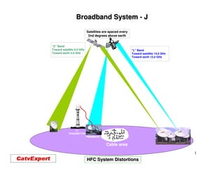
  • 1. Broadband System - J Satellites are spaced every 2nd degrees above earth "C" Band Toward satellite 6.0 GHz "L" Band Toward earth 4.0 GHz Toward satellite 14.0 GHz Toward earth 12.0 GHz TV TRANSMITTER Headend Cable area 1 HFC System Distortions
  • 2. Distortions in a Broadband System. In this section we will learn how to calculate the distortions in a Broadband System. This presentation will help understand, why the system performs better closer to the headend and get worst, toward the end of the system. 2
  • 3. Distortions in a Broadband System. Here are the distortions we will covering in this section; •Distortion of second order. •Distortion of third order •Cross modulation. •Composite third order, CTB. •Composite second order, CSO. •Noise. •Hum. 3
  • 4. Distortions in a Broadband System. Formulas for calculating distortions on a HFC, Broadband system, CATV. 4
  • 5. Distortions in a Broadband System. After you have decided the number of customers per NODE, you’ll need to determinate at what level you system will operate. This is done by the following: •Determinate the optical level (light level) at the NODE, this will give you distortion level at the NODE. •You then need to determinate the length of the coaxial system. (how many amp. In cascade) •You will have to determinate the operating level of the amplifiers. •Then you can calculate the distortion of each leg of the system. Light level JXP dBm 0 dBm 1.0dBm 53.0 dB 54.0 dB C/N P. S. -65.0dB -65.0 dB CTB RF level dBmV -65.0dB -65.0 dB CSO 5
  • 6. Distortion in a Broadband System. Attached are the technical specifications of a 870 MHz optical NODE 6
  • 7. Noise Distortion in a Broadband System. Noise distortion for one RF amplifier: Formula is: C-N ratio = Input signal (dBmV) + 59.2 – (Noise Figure of each amplifier). It is always a good practice to add one (1) dB to the noise figure given by manufacture, due of the cable equalizer that will be installed at their input. 16 dBmV input 59.2 + 16 - (10+1)=64.2 dB C/N Remark: 10 dB Noise Figure 59.2 dB is the thermal noise for: 4.2 MHz of bandwidth on a CATV amplifier. 7
  • 8. Noise Distortion in a Broadband System. Attached are the technical specifications of a 870 MHz RF amplifier 8
  • 9. Distortion in a Broadband System. All distortions. You need to calculate the distortions of the CASCADE of the RF amplifiers and then married (add) these distortions to the Optical NODE, to get the actual system’s distortions. NODE CASCADE of RF amplifiers Then add the NODE distortions. 9
  • 10. Distortion in a Broadband System. Carrier to Noise For a cascade of amplifier, where all of the amplifiers operate at the same level (input and output) C/Ns= C/N - log N 10 The formula is: N = Number of amplifier in the cascade. Formula for different operating level: -C/N1 -C/N2 -C/N n C/Ns= -10log10 10 10 10 10 +10 +...10 10
  • 11. Distortion in a Broadband System. Carrier to Noise To sum differing Carrier to Noise ratios: 10 * 10 log10 2 10 * 10 log10 3 C-N 10 * 10 log10 ( -C/N 1 + -C/N 2 ) 10 10 10 10 10 * 10 log10 ( -C/N 1 + -C/N 2 ) 10 10 10 10 To do this calculation, things you need to know are; the distortion (Carrier to Noise or Noise figure) of each amplifier, their spacing at ***MHz and their operating level, so you’ll know their input level. 11
  • 12. Distortion in a Broadband System. Carrier to CSO CSO 15 * 10 log10 2 15 * 10 log10 3 15 * 10 log10 ( -CTB 1 + -CTB 2 ) 10 10 10 10 15 * 10 log10 ( -CTB 1 + -CTB 2 ) 10 10 10 10 15 * 10 log10 ( -CTB 1 + -CTB 2 ) Composite Second Order: 10 10 10 10 •Is always given as negative number. •For each 1 dB in change of output level, the change in CSO will be 1 dB. •Each time we double the cascade, CSO distortion get worse by 3.01 dB. 12
  • 13. Distortion in a Broadband System. CTB & X-Modulation Xmod. 20log10 2 20log10 3 CTB. 20 * 10 log10 ( -XM 1 -XM 2 ) + 20 10 20 10 20 * 10 log10 ( -XM 1 -XM 2 ) + 20 10 20 10 Crossmodulation & CTB: 20 * 10 log10 ( -XM 1 -XM 2 ) + 20 10 20 10 •Is always given as negative number. •For each dB change in output level, the change in CTB and Xmod. is 2.0 dB. •Each time we double the cascade, CTB and Xmod. get worse by 6.02 dB. 13
  • 14. Distortion in a Broadband System. CTB & XModulation For a cascade of amplifiers, when they operates at the same output level, here is the formulas to calculate the CTB and Cross Modulation distortion. The formula is: CTB’s or Xmod’s - 20 log10 N N = Number of amplifier in the cascade. 14
  • 15. Distortion in a Broadband System. HUM Hum can be measured in dB or in percentage (%). Since hum is often caused by a defective piece of equipment, HUM is usually not cascade distortion dependant. HUM is generally measured on a CW channel (channel without modulation). If your HUM distortion is measured in dB, the formula below permits to transfer dB HUM to HUM percentage (%). The formula below shows the calculation of a -60 dB HUM distortion to % HUM. % = ( R / R) * 100 10 20 % = ( 60 ) *100 10 20 % = ( 10 3 ) * 100 % = .001 X 100 = 0.1% 15
  • 16. Distortion in a Broadband System. All Distortions measurements. Cascade (N) 10*log (N) 15*log (N) 20*log (N) 1 0.00 0.00 0.00 2 3.01 4.52 6.02 3 4.77 7.16 9.54 4 6.02 9.03 12.04 5 6.99 10.48 13.98 6 7.78 11.67 15.56 7 8.45 12.68 16.90 8 9.03 13.55 18.06 9 9.54 14.31 19.08 10 10.00 15.00 20.00 11 10.41 15.62 20.83 12 10.79 16.19 21.58 13 11.17 16.71 22.28 14 11.46 17.19 22.92 Distortions calculation for a series of amplifiers, when all amplifier have the same output level. This calculate C/N, CSO and CTB of a cascade of amplifiers. At the 5th amplifier C/N will be: 6.99 dB, CSO will be: 10.48 dB and CTB will be: 13.98 dB worst than the first amplifier of the cascade, 16
  • 17. Distortions in a Broadband System. CTB, Xmod with different Operating Level. dB 0.00 0.10 0.20 0.30 0.40 0.50 0.60 0.70 0.80 0.90 0 6.02 5.97 5.92 5.87 5.82 5.77 5.73 5.68 5.63 5.58 1 5.53 5.49 5.44 5.39 5.35 5.30 5.26 5.21 5.17 5.12 2 5.08 5.03 4.99 4.95 4.90 4.86 4.82 4.78 4.73 4.69 3 4.65 4.61 4.57 4.53 4.49 4.45 4.41 4.37 4.33 4.29 4 4.25 4.21 4.17 4.13 4.10 4.06 4.02 3.98 3.95 3.91 5 3.88 3.84 3.80 3.77 3.73 3.70 3.66 3.63 3.60 3.56 6 3.53 3.50 3.46 3.43 3.40 3.36 3.33 3.30 3.27 3.24 7 3.21 3.18 3.15 3.12 3.09 3.06 3.03 3.00 2.97 2.94 8 2.91 2.88 2.85 2.83 2.80 2.77 2.74 2.72 2.69 2.66 9 2.64 2.61 2.59 2.56 2.53 2.51 2.48 2.46 2.44 2.41 10 2.39 2.36 2.34 2.32 2.29 2.27 2.25 2.22 2.20 2.18 11 2.16 2.13 2.11 2.09 2.07 2.05 2.03 2.01 1.99 1.97 12 1.95 1.93 1.91 1.89 1.87 1.85 1.83 1.81 1.79 1.77 13 1.75 1.74 1.72 1.70 1.68 1.67 1.65 1.63 1.61 1.60 14 1.58 1.56 1.55 1.53 1.51 1.50 1.48 1.47 1.45 1.44 15 1.42 1.41 1.39 1.38 1.36 1.35 1.33 1.32 1.31 1.29 16 1.28 1.26 1.25 1.24 1.22 1.21 1.20 1.19 1.17 1.16 17 1.25 1.14 1.12 1.11 1.10 1.09 1.08 1.06 1.05 1.04 18 1.03 1.02 1.01 1.00 0.99 0.98 0.96 0.95 0.94 0.93 19 0.92 0.91 0.90 0.89 0.88 0.87 0.86 0.86 0.85 0.84 20 0.82 0.80 0.78 0.76 0.75 0.74 0.72 0.70 0.69 0.68 You must removed the reading to the lowest of the two levels. Trunk Distortion = 71.45 dB – Bridger Distortion = 61.44 dB or 10.20 dB diff. = 2.34 dB 61.44 – 2.34 = 59.10 dB 17
  • 18. Distortions in a Broadband System. 2nd Order, C/N with different Operating Level. dB 0.00 0.10 0.20 0.30 0.40 0.50 0.60 0.70 0.80 0.90 0 3.01 2.96 2.91 2.86 2.81 2.77 2.72 2.67 2.63 2.58 1 2.54 2.50 2.45 2.41 2.37 2.32 2.28 2.24 2.20 2.16 2 2.12 2.09 2.05 2.01 1.97 1.94 1.90 1.87 1.83 1.80 3 1.76 1.73 1.70 1.67 1.63 1.60 1.57 1.54 1.51 1.48 4 1.46 1.43 1.40 1.37 1.35 1.32 1.29 1.27 1.24 1.22 5 1.19 1.17 1.15 1.12 1.10 1.08 1.06 1.04 1.01 0.99 6 0.97 0.95 0.93 0.91 0.90 0.88 0.86 0.84 0.82 0.81 7 0.97 0.77 0.76 0.74 0.73 0.71 0.70 0.68 0.67 0.65 8 0.64 0.63 0.61 0.60 0.59 0.57 0.56 0.55 0.54 0.53 9 0.51 0.50 0.49 0.48 0.47 0.46 0.45 0.44 0.43 0.42 10 0.41 0.40 0.40 0.39 0.38 0.37 0.36 0.35 0.35 0.34 11 0.33 0.32 0.32 0.31 0.30 0.30 0.29 0.28 0.28 0.27 12 0.27 0.26 0.25 0.25 0.24 0.24 0.23 0.23 0.22 0.22 13 0.21 0.21 0.20 0.20 0.19 0.19 0.19 0.18 0.18 0.17 14 0.17 0.17 0.16 0.16 0.15 0.15 0.15 0.14 0.14 0.14 15 0.14 0.13 0.13 0.13 0.12 0.12 0.12 0.12 0.11 0.11 16 0.11 0.11 0.10 0.10 0.10 0.10 0.09 0.09 0.09 0.09 17 0.09 0.08 0.08 0.08 0.08 0.08 0.07 0.07 0.07 0.07 18 0.07 0.07 0.07 0.06 0.06 0.06 0.06 0.06 0.06 0.06 19 0.05 0.05 0.05 0.05 0.05 0.05 0.05 0.05 0.05 0.04 20 0.04 0.04 0.04 0.04 0.04 0.04 0.04 0.04 0.04 0.04 You must removed the reading to the lowest of the two levels. Trunk distortion = 52.09 dB – Bridger distortion = 48.23dB or = 3.86 diff. = (1.48 dB) 48.23 – 1.48 = 46.75 dB 18
  • 19. Distortions in a Broadband System. Operating an RF Amplifier at Different Level. 870 MHz 870 50 MHz 50 MHz MHz to status monitoring -20 dB 870 50 MHz MHz 40 MHz 5 JXP RF/ RF MHz AC 870 AC MHz -20 dB 50 MHz RF/ EQ JXP BODE BRD JXP 5 40 AC RF MHz MHz AC ADU JXP Manual Gain 5 40 Control -20 dB MHz MHz 5 40 ICS JXP MHz MHz from fuse status monitoring -20 dB -16 dB fuse ICS EQ JXP JXP Drive 24 Vdc to status vcc Power monitoring Supply 90 / 60 Vac fuse If we increase the input of this amplifier, we will If we get this amplifier to works at +45.0 dBmV and his increase the Carrier to Noise of the amplifier. For distortions level are –75.0 for CTB, -74.0 dB for CSO, CTB, CSO, every increase of 1.0 dB at the input, the Carrier to and if we increase his output to +47.0 dBmV, the CTB dBmV, Noise of the amplifier will better itself by 1.0 dB. level will now be –71.0 dB and the CSO will now be – Let say this amplifier has 10.0 dB of Noise and you 72.0 dB. hit the amplifier by a level of +10.0 dBmV, his C/N For every increase of 1.0 dB at the output of the will be 59+10-10=59.0 dB C/N. If you hit the same 59+10- amplifier, the CTB will get worse by 2.0 dB and the amplifier at +12.0 dBmV, his C/N will now be 59+12- 59+12- CSO will get worse by 1.0 dB 10=61.0 dB C/N 19
  • 20. Distortions in a Broadband System. Distortion on a RF Section of a HFC System. 1 2 3 4 5 6 7 8 Distortion Calculation: Cascade Specification: Input; +12 dBmV CTB = 8 x 20log10 = 18.6 dB C/N = 60.0 - 9.03 = 50.97 dB Noise Fig. = 11 dB CSO = 8 x15log10 = 13.54 CTB = -77.0 - 18.6 = 58.4 dB Output = +45 dBmV C/N = 8 x 10log10 = 9.03 CSO = -76.0 - 62.46 = 62.46 dB CTB = -77.0 dB CSO = -76.0 dB Changing the operation level: Amplifier specification: Since at the end of this cascade the distortions are good, we could lower could C/N = 59+12-11 = 60.0 dB 59+12- the output of this cascade by 1.0 dB, it input would now be 12.0 –1.0 = 11.0 CTB = -77.0 dB dBmV, then it output would then be + 44.0 dB, then the cascade would would have the following distortions: CSO = -76.0 dB C/N = 50.97 – 1.0 = 49.97 dB CTB = 58.4 + 2.0 = 60.4 dB CSO = 62.46 + 1.0 = 63.46 dB 20
  • 21. Distortions in a Broadband System. Distortion on a RF Section of a HFC System. NODE 1 2 3 4 5 6 7 8 Cascade Specification: NODE Distortion: C/N = 60.0 - 9.03 = 50.97 dB C/N = 53.0 dB CTB = -77.0 - 18.6 = 58.4 dB CTB = - 65.0 dB CSO = -76.0 - 62.46 = 62.46 dB CSO = -64.0 dB Overall Specification: C/N = 53.0 – 50.97 or 50.97 – 2.03 = 48.94 dB CTB = 65.0 – 58.4 or 58.4 – 3.33 = 55.07 dB CSO = 64.0 – 62.46 or 62.46 –2.32 = 60.14 dB Remember the minimum distortion expected at each customer are; C/N = 48.0 dB, CTB = -51.0 dB, CSO = -51.0 dB 21
  • 22. Distortions in a Broadband System. How distortions are measured on a HFC system. Last Active on System 30 Variable Bandpass Spectrum Filter Analyzer Variable RF Attenuator 22
  • 23. Distortions in a Broadband System. Distortion Measurement Calculated using a Spreadsheet. HFC system distortion Name of System : *** System Freq. : 870 MHz 77 ch. CW and 320 MHz Data @ 6 dB Lower than Analog ch. Maximum Single RF Amplifier performance gain Type of amp. : MB87S E-GaAs Max Gain 45 dB Amp. Noise Fig. : 12.0 dB @ 52 MHz 50 MHz / 550 MHz / 870 MHz Reserve Operating Oper. Level : 36 43 48 dBmV O utput No 1 & 2 gain with a TV signal at 865.25 MHz gain Oper. Gain : 38 dB Re serve . Gain : 7 dB gain Single amp. Distortion Input next Amplifier : CTB : -75.00 dB For 79 ch. and 320 MHz data 10.00 dBmV CSO : -72.00 dB " with a TV signal at 745,25 MHz C/N : 57.00 dB " Number of Amp. Coaxial System performance In cascade 5 Number of amp. In cascade Output No 2 & 3 C TB : -61.02 dB For 77 ch. and 200 MHz data RF amp. CSO : -61.52 dB " " distortion C / N : 50.01 dB " " HFC Complete system performance distortion Input dBm; Amplifier Cascade 0.0 Opt. Rx fiber 5 With 2 outputs same leve l Optical Complete System System CTB : -65.00 dB -56.76 For 79 ch. and 320 MHz data CSO : -62.00 dB -58.74 " " C / N : 52.00 dB 47.88 " " 23 coaxial/calcul/dist77-750
  • 24. Distortions in a Broadband System. Distortion Measurement Accepted at all the Customer. 6.0 MHz 0 -10 Signal-to- -20 Interference limites -30 dB -40 -50 C C CTB C C S S S S -60 O O O O -70 3.59 MHz 24 4.5 MHz
  • 25. Test! 25
  • 26. •What is the best Carrier to Noise possible for a 6 MHz RF signal? •______________________________________________________________ •A + 10 dBmV input for an amp. with 11.5 dB Noise Fig. What is his C/N? •_______________________________________________________________ •A amp. has –65.0 dB CTB at 46.0 dBmV output, what is the CTB for a 42.0 dBmV? •_______________________________________________________________ •What does CSO stand for? •_______________________________________________________________ •Which of the two distortions, CTB or CSO degrade faster in a HFC system? •_______________________________________________________________ •First amp. Has –74.0 dB CTB, what will be the CTB after 6 amps? •_______________________________________________________________ •What is the minimum AC voltage for a modern amplifier? •_______________________________________________________________ •What is the maximum amp. Cascade on a modern HFC system> •________________________________________________________________ 26
  • 27. 27