SlideShare una empresa de Scribd logo
1 de 10
Descargar para leer sin conexión
SIMATIC S7Ć300
Analog input/output modules
General

Overview                                                           • Analog inputs and outputs
                                                                     for the S7Ć300
                                                                   • For solving even more comĆ
                                                                     plex tasks involving analog
                                                                     process signals
                                                                   • For connecting analog acĆ
                                                                     tuators and sensors without
                                                                     additional amplifiers


Application                       Analog I/O modules contain       Analog I/O modules offer the     S   Powerful analog technology;
                                  analog inputs/outputs for the    user the following advantages:       different I/O areas and high
                                  SIMATIC S7Ć300. Analog senĆ      S Optimal adaptation;                resolution enable connection
                                  sors and actuators can be          the number of inputs/outputs       of a wide variety of analog
                                  connected to the SIMATIC           can be adapted to the task         sensors and actuators
                                  S7Ć300 via these modules.          via modules that can be
                                                                     combined in any way. There
                                                                     is no need for surplus inĆ
                                                                     vestment.


Design                            Analog input modules are         Easy assembly;                   UserĆfriednly wiring;
                                  characterized by the following   the module is mounted on the     the modules are wired by
                                  mechanical features:             DIN rail and connected to the    means of a plugĆin front conĆ
                                  Compact design;                  adjacent modules via bus         nector. When the connector is
                                  the rugged plastic housing       connectors. There are no slot    plugged in for the first time, a
                                  contains:                        rules: The input addresses       coding element engages so
                                                                   are defined by the slots.        that the connector can only be
                                  S Red LEDs for group faults/
                                                                                                    plugged into modules of the
                                    errors
                                                                                                    same type.
                                  S Front connector protected
                                                                                                    When the module is replaced,
                                    by the front panel
                                                                                                    the front connector can be
                                  S Labeling area on the front
                                                                                                    used in its fully wired state for
                                    panel
                                                                                                    the new module of the same
                                                                                                    type.


 3/36      Siemens ST 70 · 1999
SIMATIC S7Ć300
                                                                                          Analog input/output modules
                                                                                                           SM 331 analog input modules

Overview                                                                       • Analog inputs for the
                                                                                 SIMATIC S7Ć300
                                                                               • For connecting voltage and
                                                                                 current sensors, thermoĆ
                                                                                 couples, resistors and resiĆ
                                                                                 stance thermometers


Application                             Analog input modules convert           Voltage and current sensors,
                                        analog signals from the proĆ           thermocouples, resistors and
                                        cess to digital signals for inĆ        resistance thermometers can
                                        ternal processing within the           be connected as sensors.
                                        S7Ć300.

Function                                Features also include:                 S   A variety of measuring ranĆ       S Interrupt capability:
                                        S   Configurable resolution from           ges:                                The module transmits diaĆ
                                            9 to 15 bits + sign (for differĆ       The basic current/voltage           gnostic and limit value interĆ
                                            ent conversion times)                  measuring ranges are set            rupts to the programmable
                                                                                   mechanically with range             controller's CPU.
                                                                                   cards; fine adjustment is         S Diagnostics:
                                                                                   made with the STEP 7                The module sends extensive
                                                                                   Hardware Configuration"            diagnostic information to the
                                                                                   function on a programming           CPU.
                                                                                   device.

Technical specifications

SM 331                   6ES7 331-      7KF01-0AB0                             7KB01-0AB0 / 7KB81-0AB01)         7NF00-0AB0

Number of inputs                        8                                      2                                 8
S for resistance measurements           4                                      1                                 Ċ
Rated load voltage L+                   24 V DC                                24 V DC                           Ċ
S Polarity reversal protection          Yes                                    Yes                               Ċ
Input ranges/
input resistance
S Voltage                               ± 80 mV/10 Mohms                       ± 80 mV/10 Mohms                  ± 5 mV/2 Mohms
                                        ± 250 mV/10 Mohms                      ± 250 mV/10 Mohms                 1 to 5 V/2 Mohms
                                        ± 500 mV/10 Mohms                      ± 500 mV/10 Mohms                 ± 10 V/2 Mohms
                                        ± 1 V/10 Mohms                         ± 1 V/10 Mohms
                                        ± 2.5 V/100 kohms                      ± 2.5 V/100 kohms
                                        ± 5 V/100 Mohms                        ± 5 V/100 Mohms
                                        1 to 5 V/100 Mohms                     1 to 5 V/100 Mohms
                                        ± 10 V/100 Mohms                       ± 10 V/100 Mohms
S Current                               ± 10 mA/25 ohms                        ± 10 mA/25 ohms                   ± 20 mA/250 ohms
                                        ± 3.2 mA/25 ohms                       ± 3.2 mA/25 ohms                  0 to 20 mA/250 ohms
                                        ± 20 mA/25 ohms                        ± 20 mA/25 ohms                   4 to 20 mA/250 ohms
                                        0 to 20 mA/25 ohms                     0 to 20 mA/25 ohms
                                        4 to 20 mA/25 ohms                     4 to 20 mA/25 ohms
S Resistance                            150 ohms/10 Mohms                      150 ohms/10 Mohms                 Ċ
                                        300 ohms/10 Mohms                      300 ohms/10 Mohms
                                        600 ohms/10 Mohms                      600 ohms/10 Mohms
S Thermocouples                         Type E, N, J, K/10 Mohms               Type E, N, J, K/10 Mohms          Ċ
S Resistance thermometers               Pt 100 standard/ 10 Mohms              Pt 100 standard/ 10 Mohms         Ċ
                                        Ni 100 standard                        Ni 100 standard

Permissible input voltage
for voltage input                max.   20 V                                   20 V                              50 V

Permissible input current
for current input                max.   40 mA                                  40 mA                             32 mA

1) With extended temperature range

                                                                                                                     Siemens ST 70 · 1999     3/37
SIMATIC S7Ć300
Analog input/output modules
SM 331 analog input modules (continued)

Technical specifications (continued)

SM 331                     6ES7 331-      7KF01-0AB0                              7KB01-0AB0 / 7KB81-0AB01)               7NF00-0AB0

Optical isolation to backplane bus        Yes                                     Yes                                     Yes

Characteristic linearization
S for thermocouples                       Type N, E, J, K                         Type N, E, J, K                         Ċ
S for resistance thermometers             Pt 100 (standard range)                 Pt 100 (standard range)                 Ċ
                                          Ni 100 (standard range)                 Ni 100 (standard range)
Temperature compensation                  Configurable                            Configurable                            Ċ
S Internal                                Possible                                Possible                                Ċ
S External with compensation sokĆ         Possible                                Possible                                Ċ
  ket
S External with Pt 100                    Ċ                                       Ċ                                       Ċ
Conversion time2)/
resolution (per channel)
S Integration time                        2.5     16.6   20      100     ms       2.5     16.6   20      100     ms       2.5     16.7    20   100     ms
S Resolution (S=sign)
  unipolar                                9       12   12   14           bits     9       12   12   14           bits     15   15   15   15            bits
  bipolar                                 9+S     12+S 12+S 14+S         bits     9+S     12+S 12+S 14+S         bits     15+S 15+S 15+S 15+S          bits
S Interference voltage suppresĆ
  sion for interference frequency         400     60     50      10      Hz       400     60     50      10      Hz       100     60      50   10      Hz
Operating error limit
(over entire temperature range                                                                                            ± 0.1 % (voltage)
referred to input range)       max.       ±1%                                     ±1%                                     ± 0.3 % (current)
Basic error limit
(operating error limit at 25 °C, referĆ                                                                                   ± 0.05 % (voltage)
red to input range) max.                  ± 0.6 %                                 ± 0.6 %                                 ± 0.05 % (current)
Interrupts
S LimitĆvalue interrupt                   Configurable                            Configurable                            Configurable channels 0 and 2
S Diagnostics interrupt                   Configurable channels 0 and 2           Configurable channel 0                  Configurable
Diagnostics                               Red LED for group faults and errors,    Red LED for group faults and errors,    Red LED for group faults and errors,
                                          diagnostic information can be read      diagnostic information can be read      diagnostic information can be read
                                          out                                     out                                     out
Cable length (shielded)           max.    200 m (50 m at 80 mV)                   200 m (50 m at 80 mV)                   200 m
Power consumption
S from backplane bus              max.    60 mA          60 mA                    60 mA          60 mA                    130 mA
S from L+                         max.    200 mA         80 mA                    200 mA         80 mA                    Ċ
Power loss                         typ.   1.3 W                                   1.3 W                                   0.6 W
Optical isolation, tested at              500 V DC                                500 V DC                                500 V AC
Dimensions (W x H x D) in mm              40x125x120                              40x125x120                              40 x 125 x 120
Weight                                    250 g                                   250 g                                   270 g

1) With extended temperature range
2) Further specifications are required for calculating the cycle time. You can find these in the manual S7Ć300 Installation and Hardware".


Ordering data                              Order No.                                                                          Order No.

SM 331 analog input modules                                                        Shield connecting element                  6ES7 390-5AA00-0AA0
incl. labeling strips, bus connector,                                              80 mm wide, with two rows for
range cards;                                                                       4 shield terminal elements each
S with 8 inputs                            6ES7 331-7KF01-0AB0
                                                                                   Terminal element (2 pcs.)
S with 2 inputs                            6ES7 331-7KB01-0AB0
                                                                                   S for 2 cables                             6ES7 390-5AB00-0AA0
S with 2 inputs, extended temperaĆ         6ES7 331-7KB81-0AB0                       with diam. 2 to 6 mm
  ture range
                                                                                   S for 1 cable                              6ES7 390-5BA00-0AA0
S with 8 inputs, enhanced resoluĆ          6ES7 331-7NF00-0AB0                       with diam. 3 to 8 mm
  tion
                                                                                   S for 1 cable                              6ES7 390-5CA00-0AA0
Range card for analog inputs               6ES7 974-0AA00-0AA0                       with diam. 4 to 13 mm
1 module for 2 analog inputs;
                                                                                   Labeling cover                             6ES7 392-2XY00-0AA0
2 cards (spare part)
                                                                                   (10 pcs.)
Front connector (1 pc.)                                                            for signal modules (except
S 20Ćpin, with screwĆtype terminals        6ES7 392-1AJ00-0AA0                     32Ćchannel modules), function
S 20Ćpin, with springĆloaded term.         6ES7 392-1BJ00-0AA0                     modules and CPU 312 IFM
S 40Ćpin, with screwĆtype terminals        6ES7ā392-1AM00-0AA0                     Labeling strips                            6ES7 392-2XX00-0AA0
S 40Ćpin, with springĆloaded term.         6ES7ā392-1BM01-0AA0                     (10 pcs., spare part)
Bus connector 1 pc. (spare part)           6ES7 390-0AA00-0AA0                     for signal modules (except
                                                                                   32Ćchannel modules), function
                                                                                   modules and CPU 312 IFM


 3/38          Siemens ST 70 · 1999
SIMATIC S7Ć300
                                                                                 Analog input/output modules
                                                                                    SM 331 analog input modules (continued)


                              1 L+                                  1 L+
                              2                                     2                         1   21
                                 V                                     V
                              3   A                                 3   A    0       0       A2   22
                              4                                     4                         3   23       CH0
                                                                             1       1
                                 V                                     V
                              5   A                                 5   A    2       2        4   24
                                                                                                       +   CH1
                              6                                              3       3        5   25 V –
                                 V
                              7   A                                          4       4        6   26
                                                                                                       +
                                                                                                           CH2
                              8                                              5       5        7   27 V –
                                 V                                                            8   28
                              9   A                                          6       6                 +
                                                                                                           CH4
                                                                                              9   29 V –
                              10                                    10       7       7

                                                                                              10 30
                              COMP                                  COMP                      11 31
                              11                                    11
                              12                                                              12 32
                                                                                                      +
                                   V                                                                       CH5
                              13    A                                        0       0        13 33 V –
                              14                                             1       1        14 34
                                                                                                      +    CH6
                              15   V                                         2       2        15 35 V –
                                    A
                              16                                             3       3        16 36
                                                                                                      +    CH7
                              17   V                                         4       4        17 37 V –
                                    A
                              18                                             5       5        18 38
                                                                                                      +    CH4
                              19   V                                         6       6        19 39 V –
                                    A
                                                                             7       7        20 40
                              20                                    20
                               M                                     M


         6ES7 331Ć7KF01Ć0AB0                   6ES7 331Ć7KB01Ć0AB0          6ES7 331Ć1BL00Ć0AA0
                                               6ES7 331Ć7KB81Ć0AB0


Fig. 1/10 Terminal connection diagram of the SM 331 analog input modules


                                                                                                                 Siemens ST 70 · 1999   3/39
SIMATIC S7Ć300
Analog input/output modules
SM 332 analog output modules

Overview                                                                      • Analog outputs for SIMATIC
                                                                                S7Ć300
                                                                              • For connecting analog
                                                                                actuators


Application                              Analog output modules conĆ
                                         vert digital signals from the
                                         S7Ć300 to analog signals for
                                         the process.

Function                                 Features also include:               S Interrupt capability:
                                         S   Resolution 12 to 15 bits.          The module transmits diaĆ
                                         S   A variety of voltage and curĆ      gnostic and limit value interĆ
                                             rent ranges:                       rupts to the programmable
                                             Ranges are set indepenĆ            controller's CPU on occurĆ
                                             dently for each channel by         rence of errors.
                                             means of parameterization        S Diagnostics:
                                             software.                          The module sends extensive
                                                                                diagnostic information to the
                                                                                CPU.

Technical specifications

SM 332                       6ES7 332-   5HD01-0AB0                          5HB01-0AB0                          7ND00-0AB0
                                                                             5HB81-0AB01)
Number of outputs                        4                                   2                                   4
Rated load voltage                       24 V DC                             24 V DC                             24 V DC
Output ranges
S Voltage outputs                        0 to 10 V; ± 10 V; 1 to 5 V         0 to 10 V; ± 10 V; 1 to 5 V         0 to 10 V; ± 10 V; 1 to 5 V
S Current outputs                        4 to 20 mA; ± 20 mA;                4 to 20 mA; ± 20 mA;                4 to 20 mA; ± 20 mA;
                                         0 to 20 mA                          0 to 20 mA                          0 to 20 mA
Load impedance
S Voltage outputs             max.       1 kohms                             1 kohms                             1 kohms
S Current outputs             max.       0.5 kohms                           0.5 kohms                           0.5 kohms
S Capacitive loads            max.       1 mF                                1 mF                                1 mF
S Inductive loads             max.       1 mH                                1 mH                                1 mH
Voltage output
S ShortĆcircuit protection               Yes                                 Yes                                 Yes
S ShortĆcircuit current       max.       25 mA                               25 mA                               40 mA
Power output
S OpenĆcircuit current        max.       18 V                                18 V                                18 V
Optical isolation
to backplane bus                         Yes                                 Yes                                 Yes
Resolution                               11 bits + sign                      11 bits + sign                      15 bits + sign
                                         (at "10 V; "20 mA, 4 to             (at "10 V; "20 mA, 4 to
                                         20 mA, 1 to 5 V);                   20 mA, 1 to 5 V);
                                         12 bits                             12 bits
                                         at 0 to 10 V; to 20 mA)             at 0 to 10 V; to 20 mA)
Conversion time per channel max.         0.8 ms                              0.8 ms                              1.5 ms
Settling time
S Resistive loads                        0.1 ms                              0.1 ms                              0.2 ms
S Capacitive loads                       3.3 ms                              3.3 ms                              0.5 ms
S Inductive loads                        0.5 ms                              0.5 ms                              0.5 ms
Substitute values                        Configurable                        Configurable                        Configurable

1) With extended temperature range


 3/40           Siemens ST 70 · 1999
SIMATIC S7Ć300
                                                                                               Analog input/output modules
                                                                                                 SM 332 analog output modules (continued)

Technical specifications (continued)

SM 332                            6ES7 332-   5HD01-0AB0                            5HB01-0AB0                            7ND00-0AB0
                                                                                    5HB81-0AB01)
Operational limit
(0 to 60 °C, referred to
output range)
S Voltage                                     " 0.5 %                               " 0.5 %                               " 0.12 %
S Current                                     " 0.6 %                               " 0.6 %                               " 0.18 %
Basic error
(operational limit at 25 °C,
referred to output range)
S Voltage                                     " 0.2 %                               " 0.2 %                               " 0.01 %
S Current                                     " 0.3 %                               " 0.3 %                               " 0.01 %
Interrupts
S Diagnostic interrupt                        Yes                                   Yes                                   Yes
Diagnostics                                   Red LED for group fault error;        Red LED for group fault error;        Red LED for group fault error;
                                              diagnostics information can be read   diagnostics information can be read   diagnostics information can be read
                                              out                                   out                                   out
Cable length (shielded)            max.       200 m                                 200 m                                 200 m
Power consumption
S from backplane bus               max.       60 mA                                 60 mA                                 60 mA
S from L+                          max.       240 mA                                135 mA                                240 mA
Power loss                          typ.      3W                                    3W                                    3W
Optical isolation, tested at                  500 V DC                              500 V DC                              500 V DC
Dimensions (W x H x D) in mm                  40 x 125 x 120                        40 x 125 x 120                        40 x 125 x 120
Weight                          approx.       220 g                                 220 g                                 220 g

1) With extended temperature range

Ordering data                                 Order No.                                                                     Order No.

SM 332 analog output modules                                                        Terminal element (2 pcs.)
incl. labeling strips, bus connector                                                S for 2 cables                         6ES7 390-5AB00-0AA0
S with 4 outputs                              6ES7 332-5HD01-0AB0                     with diam. 2 to 6 mm
S with 4 outputs, 15 bits                     6ES7 332-7ND00-0AB0                   S for 1 cable                          6ES7 390-5BA00-0AA0
S with 2 outputs                              6ES7 332-5HB01-0AB0                     with diam. 3 to 8 mm
S with 2 outputs, extended tempeĆ             6ES7 332-5HB81-0AB0                   S for 1 cable                          6ES7 390-5CA00-0AA0
  rature range                                                                        with diam. 4 to 13 mm

Bus connector                                 6ES7 390-0AA00-0AA0                   Labeling cover                         6ES7 392-2XY00-0AA0
(1 pc., spare part)                                                                 (10 pcs.)
                                                                                    for signal modules (except
Front connector (1 pc.)
                                                                                    32Ćchannel modules), function
S 20Ćpin, with screwĆtype termiĆ              6ES7 392-1AJ00-0AA0                   modules and CPU 312 IFM
  nals
S 20Ćpin, with springĆloaded termiĆ           6ES7 392-1BJ00-0AA0                   Labeling strips                        6ES7 392-2XX00-0AA0
  nals                                                                              (10 pcs., spare part)
                                                                                    for signal modules (except
Shield-connecting element                     6ES7 390-5AA00-0AA0                   32Ćchannel modules), function
80 mm wide, with two rows for                                                       modules and CPU 312 IFM
4 shield terminal elements each


                           1 L+                                      1 L+                                       1 L+

                           3                                         3                                          3
                           4                                         4                                          4
                           5                                         5                                          5
                           6                                         6                                          6
                           7                                         7                                          7
                           8                                         8                                          8
                           9                                         9                                          9
                           10                                        10                                         10


                           11                                                                                   11
                           12                                                                                   12
                           13                                                                                   13
                           14                                                                                   14
                           15                                                                                   15
                           16                                                                                   16
                           17                                                                                   17
                           18                                                                                   18


                           20                                        20                                         20
                            M                                         M                                          M


   6ES7 332Ć5HD01Ć0AB0                          6ES7 332Ć5HB01Ć0AB0                     6ES7 332Ć7ND00Ć0AB0
                                                6ES7 332Ć5HB81Ć0AB0

Fig. 1/11 Terminal connection diagram of the SM 332 analog output modules

                                                                                                                            Siemens ST 70 · 1999        3/41
SIMATIC S7Ć300
Analog input/output modules
SM 334 analog input/output module

Overview                                                                          • Analog inputs and outputs
                                                                                    for SIMATIC S7Ć300
                                                                                  • For connecting analog senĆ
                                                                                    sors and actuators


Application                                  The analog input/output moĆ          S   digital signals from the
                                             dule converts                            S7Ć300 to analog signals
                                             S   analog signals from the proĆ         for the process.
                                                 cess to digital values for the
                                                 S7Ć300, and

Function                                     The analog input/output moĆ          S   8Ćbit output resolution               S   Measuring ranges of 0 to
                                             dule also includes:                                                                10 V or 0 to 20 mA:
                                             S   4 inputs, 2 outputs                                                            The range is selected by
                                             S   8Ćbit input resolution                                                         means of the appropriate
                                                                                                                                connections on the module.

Technical specifications
SM 334                      6ES7 334- 0CE01-0AA0              0KE00-0AB0          SM 334                   6ES7 334-   0CE01-0AA0         0KE00-0AB0

Inputs                                  4                     4                   Outputs                              2                  2
S for resistance measurement            Ċ                     4                   Output ranges
Rated load voltage L+                   24 V DC               24 V DC             S Voltage outputs                    0 to 10 V          0 to 10 V
Input ranges/                           0 to 10V/100kohms     0 to                S Current outputs                    0 to 20 mA         Ċ
input resistance                        0 to 20mA/            10V/100kohms        Load impedance
                                        50kohms               10Ćkohm resiĆ       S Voltage outputs             min.   5 kohms            2.5 kohms
                                                              stance, Pt 100      S Current outputs             max.   0.3 kohms          Ċ
Permissible input voltage                                                         S Capacitive loads            max.   1 mF               1 mF
for voltage input              max.     20 V                  20 V                S Inductive loads             max.   1 mH               Ċ
Permissible input current                                                         Voltage output
for current input              max.     20 mA                 Ċ                   S ShortĆcircuit protection           Yes                Yes
Optical isolation                       No                    Yes                 S ShortĆcircuit current       max.   11 mA              10 mA
Resolution                              8 bits                12 bits             Power output
Operational limit                                                                 S OpenĆcircuit current        max.   15 V               Ċ
(over entire temperature range, reĆ                                               Optical isolation
ferred to input range)                                                            to backplane bus                     No                 Yes
S   Voltage                             " 0.9 %               " 0.7 %             Resolution                           8 bits             12 bits
S   Current                             " 0.8 %               Ċ                   Cycle time (all channels/AI + AO)    5 ms               85 ms
S   10 kohms                            Ċ                     " 3.0 %             Settling time
S   Pt 100                              Ċ                     " 0.7 %
                                                                                  S Resistive loads             max.   0.3 ms             0.8 ms
Basic error                                                                       S Capacitive loads            max.   3 ms               0.8 ms
(operational limit at 25 _C, referred
                                                                                  S Inductive loads             max.   0.3 ms             Ċ
to output range)
                                                                                  Substitute values                    Ċ                  Ċ
S   Voltage                             " 0.7 %               " 0.5 %
                                                                                  Operational limit
S   Current                             " 0.6 %               Ċ
                                                                                  (0 to 60 _C, referred to output
S   10 kohms                            Ċ                     " 2.0 %             range)
S   Pt 100                              Ċ                     " 0.5 %
                                                                                  S Voltage                            " 0.6 %            " 1.0 %
Interrupts                                                                        S Current                            " 1.0 %            Ċ
S LimitĆvalue interrupt                 Ċ                     Ċ
S Diagnostics interrupt                 Ċ                     Ċ
Diagnostics                             Ċ                     Ċ


    3/42       Siemens ST 70 · 1999
SIMATIC S7Ć300
                                                                                                    Analog input/output modules
                                                                                                                SM 334 analog input/output module
                                                                                                                                       (continued)

Technical specifications
SM 334                    6ES7 334- 0CE01-0AA0                  0KE00-0AB0               SM 334                 6ES7 334-    0CE01-0AA0       0KE00-0AB0

Outputs (continued)                                                                      General
Basic error                                                                              Cable length (shielded)     max.    200 m            100 m
(operational limit at 25 _C, referred                                                    Power consumption
to output range)                                                                         S from S7Ć300 backplane
S Voltage                                      " 0.4 %          " 0.85 %                   bus                       max.    55 mA            60 mA
S Current                                      " 0.8 %          Ċ                        S from L+                   max.    110 mA           80 mA
Interrupts                                                                               Power loss                   typ.   2.6 ohms         2 ohms
S Diagnostic interrupt                         Ċ                Ċ                        Dimensions (W x H x D) in mm        40 x 125 x 120   40 x 125 x 120
                                                                                         Weight                              285 g            200 g


Ordering data                                      Order No.                                                                     Order No.

SM 334 analog input/output mo-                     6ES7 334-0CE01-0AA0                   Terminal element (2 pcs.)
dule1)                                                                                   S for 2 cables                         6ES7 390-5AB00-0AA0
incl. labeling strips, bus connecĆ                                                         with diam. 2 to 6 mm
tor;                                                                                     S for 1 cable                          6ES7 390-5BA00-0AA0
S with 4 inputs and 2 outputs                      6ES7 334-0CE01-0AA0                     with diam. 3 to 8 mm
S with 4 inputs and 2 outputs; resiĆ               6ES7 334-0KE00-0AB0                   S for 1 cable                          6ES7 390-5CA00-0AA0
  stance measurement, Pt 100                                                               with diam. 4 to 13 mm
Bus connector                                      6ES7 390-0AA00-0AA0                   Labeling cover                         6ES7 392-2XY00-0AA0
(1 pc., spare part)                                                                      (10 pcs.)
                                                                                         for signal modules (except
Front connector (1 pc.)
                                                                                         32Ćchannel modules), function
S 20Ćpin, with screwĆtype termiĆ                   6ES7 392-1AJ00-0AA0
                                                                                         modules and CPU 312 IFM
  nals
S 20Ćpin, with springĆloaded termiĆ                6ES7 392-1BJ00-0AA0                   Labeling strips                        6ES7 392-2XX00-0AA0
  nals                                                                                   (10 pcs., spare part)
                                                                                         for signal modules (except
Shield connecting element                          6ES7 390-5AA00-0AA0
                                                                                         32Ćchannel modules), function
80 mm wide, with two rows for
                                                                                         modules and CPU 312 IFM
4 shield terminal elements each


                                                                         1 L+ 24 V
                             1 L+                                        2
                             2
                                 V                                       3
                             3
                                                                         4
                             4 A
                                                                         5
                             5
                                 V                                       6
                             6
                                                                         7
                             7 A
                                                                         8
                             8
                                 V                                       9
                             9
                                                                         10
                             10 A
                                       M
                                                                              V

                                                                         11
                             11 L+ V                                     12
                             12
                                                                         13
                             13
                                 A                                       14   V
                             14            V
                                                                         15
                             15
                                                                         16
                             16            A
                                                                         17          V
                             17            V
                                                                         18
                             18
                                                                         19          V
                             19            A
                                                                         20
                             20                                           M
                                       M


      6ES7 334Ć0CE00Ć0AA0                                 6ES7 334Ć0KE00Ć0AB0

Fig. 1/12 Terminal connection diagram of the SM 334 analog input/output module


                                                                                                                                 Siemens ST 70 · 1999     3/43
SIMATIC S7Ć300
Analog input/output modules
SM 338 POS input module

Overview                                                                 • Interface between up to 3
                                                                           absolute encoders (SSI)
                                                                           and the CPU
                                                                         • For providing the position
                                                                           encoder values for further
                                                                           processing in the STEP 7
                                                                           program
                                                                         • Enables the controller to reĆ
                                                                           spond direct to encoder
                                                                           values in mobile systems.


Application                           The POS input module conĆ          The acquired values can be           In addition, SSI position enĆ
                                      verts                              processed direct in the STEP         coder statuses can be frozen
                                      S   SSI position encoder signals   7 program thus enabling diĆ          via two internal digital inputs.
                                          from the process to digital    rect response to encoder valĆ        This makes possible further
                                          values for the S7Ć300.         ues in mobile systems.               timeĆcritical applications in
                                                                                                              the area of position encoding.

Function                              The POS input module has the       S   3 SSI encoder inputs
                                      following:                         S   2 digital inputs
                                                                         S   24 V DC encoder supply

Technical specifications
General                                                                  SSI encoder inputs
Rated load voltage L+                 24 V DC                            Position encoding                    Absolute
S Acceptable range                    20.4 to 28.2 V                     Cable length (shielded)      max.    320 m at 125 kHz
Isolation                             No                                                                      160 m at 250 kHz
Encoder supply                                                                                                60 m at 500 kHz
S Output voltage                      L+ - 0.8 V                                                              20 m at 1 MHz
S Output current               max.   900 mA                             Digital inputs
Interrupts                                                               Input voltage
S Diagnostic interrupt                Configurable                       S with 1" signal                    11 to 30.2 V
Current consumption                                                      S with 0" signal                    -3 to 5 V
S from S7Ć300 backplane bus    max.   160 mA                             Input current
S from L+                      max.   10 mA                              S with 1" signal             typ.   9 mA
Power loss                     typ.   3 ohms                             S with 0" signal            max.    2 mA
Dimensions (W x H x D) in mm          40 x 125 x 120                     Input delay                          300 µs
Weight                                235 g                              Connection of 2Ćwire BERO            Yes
                                                                         Cable length (shielded)      max.    600 m


 3/44        Siemens ST 70 · 1999
SIMATIC S7Ć300
                                                                        Analog input/output modules
                                                                           SM 338 POS input module (continued)

Ordering data                                     Order No.                            Order No.

SM 338 POS input module                           6ES7 338-4BC00-0AB0
for acquiring SSI encoder values
from up to 3 absolute encoders;
incl. labeling strips, bus connectors


                                                To CPU ground
                                 1    L+ 24 V
                                 2
                                 3    M
                                 4
                                 5
                                      SSI
                                 6
                                 7
                                 8
                                 9
                                      SSI
                                10


                                 11
                                 12
                                 13
                                    SSI
                                 14
                                 15
                                 16
                                 17
                                 18
                                 19
                                20


         6ES7 338Ć4BG00Ć0AB0

Fig. 1/13 Terminal connection diagram of the SM 338 POS input module


                                                                                       Siemens ST 70 · 1999   3/45

Más contenido relacionado

La actualidad más candente

Katalog agilent-u1271a-series-handheld-digital-multimeter-tridinamika
Katalog agilent-u1271a-series-handheld-digital-multimeter-tridinamikaKatalog agilent-u1271a-series-handheld-digital-multimeter-tridinamika
Katalog agilent-u1271a-series-handheld-digital-multimeter-tridinamikaPT. Tridinamika Jaya Instrument
 
Katalog agilent-u1270-series-handheld-digital-multimeter-tridinamika
Katalog agilent-u1270-series-handheld-digital-multimeter-tridinamikaKatalog agilent-u1270-series-handheld-digital-multimeter-tridinamika
Katalog agilent-u1270-series-handheld-digital-multimeter-tridinamikaPT. Tridinamika Jaya Instrument
 
Katalog agilent-u1272a-series-handheld-digital-multimeter-tridinamika
Katalog agilent-u1272a-series-handheld-digital-multimeter-tridinamikaKatalog agilent-u1272a-series-handheld-digital-multimeter-tridinamika
Katalog agilent-u1272a-series-handheld-digital-multimeter-tridinamikaPT. Tridinamika Jaya Instrument
 
Advanced motion controls sr30a40ac
Advanced motion controls sr30a40acAdvanced motion controls sr30a40ac
Advanced motion controls sr30a40acElectromate
 
Universal modules TXM1.8x Siemens
Universal modules TXM1.8x SiemensUniversal modules TXM1.8x Siemens
Universal modules TXM1.8x SiemensJustin Hoang
 
NF Corp Programmable AC/DC Power Source ec750 sa_1000sa
NF Corp Programmable AC/DC Power Source  ec750 sa_1000saNF Corp Programmable AC/DC Power Source  ec750 sa_1000sa
NF Corp Programmable AC/DC Power Source ec750 sa_1000saNIHON DENKEI SINGAPORE
 
Advanced motion controls azbe10a20
Advanced motion controls azbe10a20Advanced motion controls azbe10a20
Advanced motion controls azbe10a20Electromate
 
Brosur Metrel MI 2892 Power Master
Brosur Metrel MI 2892 Power MasterBrosur Metrel MI 2892 Power Master
Brosur Metrel MI 2892 Power MasterPT. Siwali Swantika
 
Mts c series core-cs_cm_data_sheet
Mts c series core-cs_cm_data_sheetMts c series core-cs_cm_data_sheet
Mts c series core-cs_cm_data_sheetElectromate
 
Advanced motion controls azbe60a8
Advanced motion controls azbe60a8Advanced motion controls azbe60a8
Advanced motion controls azbe60a8Electromate
 
Advanced motion controls azbh60a8
Advanced motion controls azbh60a8Advanced motion controls azbh60a8
Advanced motion controls azbh60a8Electromate
 
Advanced motion controls azbe25a20
Advanced motion controls azbe25a20Advanced motion controls azbe25a20
Advanced motion controls azbe25a20Electromate
 
Adcmt SS9620 PV Cell Evaluation System
Adcmt SS9620 PV Cell Evaluation SystemAdcmt SS9620 PV Cell Evaluation System
Adcmt SS9620 PV Cell Evaluation SystemNIHON DENKEI SINGAPORE
 

La actualidad más candente (16)

Katalog agilent-u1271a-series-handheld-digital-multimeter-tridinamika
Katalog agilent-u1271a-series-handheld-digital-multimeter-tridinamikaKatalog agilent-u1271a-series-handheld-digital-multimeter-tridinamika
Katalog agilent-u1271a-series-handheld-digital-multimeter-tridinamika
 
Katalog agilent-u1270-series-handheld-digital-multimeter-tridinamika
Katalog agilent-u1270-series-handheld-digital-multimeter-tridinamikaKatalog agilent-u1270-series-handheld-digital-multimeter-tridinamika
Katalog agilent-u1270-series-handheld-digital-multimeter-tridinamika
 
Katalog agilent-u1272a-series-handheld-digital-multimeter-tridinamika
Katalog agilent-u1272a-series-handheld-digital-multimeter-tridinamikaKatalog agilent-u1272a-series-handheld-digital-multimeter-tridinamika
Katalog agilent-u1272a-series-handheld-digital-multimeter-tridinamika
 
Acs712
Acs712Acs712
Acs712
 
Sistem breaker pro abb
Sistem breaker pro abbSistem breaker pro abb
Sistem breaker pro abb
 
Advanced motion controls sr30a40ac
Advanced motion controls sr30a40acAdvanced motion controls sr30a40ac
Advanced motion controls sr30a40ac
 
Universal modules TXM1.8x Siemens
Universal modules TXM1.8x SiemensUniversal modules TXM1.8x Siemens
Universal modules TXM1.8x Siemens
 
NF Corp Programmable AC/DC Power Source ec750 sa_1000sa
NF Corp Programmable AC/DC Power Source  ec750 sa_1000saNF Corp Programmable AC/DC Power Source  ec750 sa_1000sa
NF Corp Programmable AC/DC Power Source ec750 sa_1000sa
 
Advanced motion controls azbe10a20
Advanced motion controls azbe10a20Advanced motion controls azbe10a20
Advanced motion controls azbe10a20
 
Brosur Metrel MI 2892 Power Master
Brosur Metrel MI 2892 Power MasterBrosur Metrel MI 2892 Power Master
Brosur Metrel MI 2892 Power Master
 
Mts c series core-cs_cm_data_sheet
Mts c series core-cs_cm_data_sheetMts c series core-cs_cm_data_sheet
Mts c series core-cs_cm_data_sheet
 
Advanced motion controls azbe60a8
Advanced motion controls azbe60a8Advanced motion controls azbe60a8
Advanced motion controls azbe60a8
 
9322 Hioki Differential Probe
9322 Hioki Differential Probe9322 Hioki Differential Probe
9322 Hioki Differential Probe
 
Advanced motion controls azbh60a8
Advanced motion controls azbh60a8Advanced motion controls azbh60a8
Advanced motion controls azbh60a8
 
Advanced motion controls azbe25a20
Advanced motion controls azbe25a20Advanced motion controls azbe25a20
Advanced motion controls azbe25a20
 
Adcmt SS9620 PV Cell Evaluation System
Adcmt SS9620 PV Cell Evaluation SystemAdcmt SS9620 PV Cell Evaluation System
Adcmt SS9620 PV Cell Evaluation System
 

Similar a 331 7kf01

Asi : Actuator Sensor Interface
Asi : Actuator Sensor InterfaceAsi : Actuator Sensor Interface
Asi : Actuator Sensor Interfaceprashob7
 
compliant charging controller for electric vehicle
compliant charging controller for electric vehiclecompliant charging controller for electric vehicle
compliant charging controller for electric vehiclecarloscostabr
 
7380969 Line Follower Using At89c51
7380969 Line Follower Using At89c517380969 Line Follower Using At89c51
7380969 Line Follower Using At89c51biharimukund
 
Wireless Gesture Controlled Tank Toy- Transmitter
Wireless Gesture Controlled Tank Toy- TransmitterWireless Gesture Controlled Tank Toy- Transmitter
Wireless Gesture Controlled Tank Toy- TransmitterNeeraj Purohit
 
line following robot
line following robotline following robot
line following robotRehnaz Razvi
 
IRJET- IoT based Industrial Automation
IRJET-  	  IoT based Industrial AutomationIRJET-  	  IoT based Industrial Automation
IRJET- IoT based Industrial AutomationIRJET Journal
 
Subir presentation
Subir presentationSubir presentation
Subir presentationjbpatel7290
 
Digitalvoltmeterppt 120914
Digitalvoltmeterppt 120914Digitalvoltmeterppt 120914
Digitalvoltmeterppt 120914sparkle786
 
Rsf ms 2x_series_catalog
Rsf ms 2x_series_catalogRsf ms 2x_series_catalog
Rsf ms 2x_series_catalogElectromate
 
IDT Integrated Circuit Distributor With Best Quality Ics For Use In Various A...
IDT Integrated Circuit Distributor With Best Quality Ics For Use In Various A...IDT Integrated Circuit Distributor With Best Quality Ics For Use In Various A...
IDT Integrated Circuit Distributor With Best Quality Ics For Use In Various A...expess-technology
 
Contactor ms-n series brochure dienhathe.org
Contactor ms-n series brochure dienhathe.orgContactor ms-n series brochure dienhathe.org
Contactor ms-n series brochure dienhathe.orgDien Ha The
 
01. sentron 3 wl brochure
01. sentron 3 wl brochure01. sentron 3 wl brochure
01. sentron 3 wl brochureangelochintu
 
Lika Electronic November 2016 Newsletter in English
Lika Electronic November 2016 Newsletter in EnglishLika Electronic November 2016 Newsletter in English
Lika Electronic November 2016 Newsletter in EnglishLika Electronic
 
Catalogue mitsubishi thiet bi dien contactor dienhathe.vn
Catalogue mitsubishi thiet bi dien contactor dienhathe.vnCatalogue mitsubishi thiet bi dien contactor dienhathe.vn
Catalogue mitsubishi thiet bi dien contactor dienhathe.vnDien Ha The
 
Plc (analog and special io)
Plc (analog and special io)Plc (analog and special io)
Plc (analog and special io)Mohamed A Hakim
 

Similar a 331 7kf01 (20)

Asi : Actuator Sensor Interface
Asi : Actuator Sensor InterfaceAsi : Actuator Sensor Interface
Asi : Actuator Sensor Interface
 
compliant charging controller for electric vehicle
compliant charging controller for electric vehiclecompliant charging controller for electric vehicle
compliant charging controller for electric vehicle
 
7380969 Line Follower Using At89c51
7380969 Line Follower Using At89c517380969 Line Follower Using At89c51
7380969 Line Follower Using At89c51
 
PLC operation part 1
PLC operation part 1PLC operation part 1
PLC operation part 1
 
Wireless Gesture Controlled Tank Toy- Transmitter
Wireless Gesture Controlled Tank Toy- TransmitterWireless Gesture Controlled Tank Toy- Transmitter
Wireless Gesture Controlled Tank Toy- Transmitter
 
line following robot
line following robotline following robot
line following robot
 
IRJET- IoT based Industrial Automation
IRJET-  	  IoT based Industrial AutomationIRJET-  	  IoT based Industrial Automation
IRJET- IoT based Industrial Automation
 
Subir presentation
Subir presentationSubir presentation
Subir presentation
 
Es9300
Es9300Es9300
Es9300
 
Digitalvoltmeterppt 120914
Digitalvoltmeterppt 120914Digitalvoltmeterppt 120914
Digitalvoltmeterppt 120914
 
7SJ81 Overcurrent Relay
7SJ81 Overcurrent Relay7SJ81 Overcurrent Relay
7SJ81 Overcurrent Relay
 
Rsf ms 2x_series_catalog
Rsf ms 2x_series_catalogRsf ms 2x_series_catalog
Rsf ms 2x_series_catalog
 
IDT Integrated Circuit Distributor With Best Quality Ics For Use In Various A...
IDT Integrated Circuit Distributor With Best Quality Ics For Use In Various A...IDT Integrated Circuit Distributor With Best Quality Ics For Use In Various A...
IDT Integrated Circuit Distributor With Best Quality Ics For Use In Various A...
 
Contactor ms-n series brochure dienhathe.org
Contactor ms-n series brochure dienhathe.orgContactor ms-n series brochure dienhathe.org
Contactor ms-n series brochure dienhathe.org
 
Acb1
Acb1Acb1
Acb1
 
01. sentron 3 wl brochure
01. sentron 3 wl brochure01. sentron 3 wl brochure
01. sentron 3 wl brochure
 
Lika Electronic November 2016 Newsletter in English
Lika Electronic November 2016 Newsletter in EnglishLika Electronic November 2016 Newsletter in English
Lika Electronic November 2016 Newsletter in English
 
Catalogue mitsubishi thiet bi dien contactor dienhathe.vn
Catalogue mitsubishi thiet bi dien contactor dienhathe.vnCatalogue mitsubishi thiet bi dien contactor dienhathe.vn
Catalogue mitsubishi thiet bi dien contactor dienhathe.vn
 
Smart Lock
Smart LockSmart Lock
Smart Lock
 
Plc (analog and special io)
Plc (analog and special io)Plc (analog and special io)
Plc (analog and special io)
 

331 7kf01

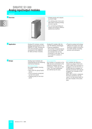
  • 1. SIMATIC S7Ć300 Analog input/output modules General Overview • Analog inputs and outputs for the S7Ć300 • For solving even more comĆ plex tasks involving analog process signals • For connecting analog acĆ tuators and sensors without additional amplifiers Application Analog I/O modules contain Analog I/O modules offer the S Powerful analog technology; analog inputs/outputs for the user the following advantages: different I/O areas and high SIMATIC S7Ć300. Analog senĆ S Optimal adaptation; resolution enable connection sors and actuators can be the number of inputs/outputs of a wide variety of analog connected to the SIMATIC can be adapted to the task sensors and actuators S7Ć300 via these modules. via modules that can be combined in any way. There is no need for surplus inĆ vestment. Design Analog input modules are Easy assembly; UserĆfriednly wiring; characterized by the following the module is mounted on the the modules are wired by mechanical features: DIN rail and connected to the means of a plugĆin front conĆ Compact design; adjacent modules via bus nector. When the connector is the rugged plastic housing connectors. There are no slot plugged in for the first time, a contains: rules: The input addresses coding element engages so are defined by the slots. that the connector can only be S Red LEDs for group faults/ plugged into modules of the errors same type. S Front connector protected When the module is replaced, by the front panel the front connector can be S Labeling area on the front used in its fully wired state for panel the new module of the same type. 3/36 Siemens ST 70 · 1999
  • 2. SIMATIC S7Ć300 Analog input/output modules SM 331 analog input modules Overview • Analog inputs for the SIMATIC S7Ć300 • For connecting voltage and current sensors, thermoĆ couples, resistors and resiĆ stance thermometers Application Analog input modules convert Voltage and current sensors, analog signals from the proĆ thermocouples, resistors and cess to digital signals for inĆ resistance thermometers can ternal processing within the be connected as sensors. S7Ć300. Function Features also include: S A variety of measuring ranĆ S Interrupt capability: S Configurable resolution from ges: The module transmits diaĆ 9 to 15 bits + sign (for differĆ The basic current/voltage gnostic and limit value interĆ ent conversion times) measuring ranges are set rupts to the programmable mechanically with range controller's CPU. cards; fine adjustment is S Diagnostics: made with the STEP 7 The module sends extensive Hardware Configuration" diagnostic information to the function on a programming CPU. device. Technical specifications SM 331 6ES7 331- 7KF01-0AB0 7KB01-0AB0 / 7KB81-0AB01) 7NF00-0AB0 Number of inputs 8 2 8 S for resistance measurements 4 1 Ċ Rated load voltage L+ 24 V DC 24 V DC Ċ S Polarity reversal protection Yes Yes Ċ Input ranges/ input resistance S Voltage ± 80 mV/10 Mohms ± 80 mV/10 Mohms ± 5 mV/2 Mohms ± 250 mV/10 Mohms ± 250 mV/10 Mohms 1 to 5 V/2 Mohms ± 500 mV/10 Mohms ± 500 mV/10 Mohms ± 10 V/2 Mohms ± 1 V/10 Mohms ± 1 V/10 Mohms ± 2.5 V/100 kohms ± 2.5 V/100 kohms ± 5 V/100 Mohms ± 5 V/100 Mohms 1 to 5 V/100 Mohms 1 to 5 V/100 Mohms ± 10 V/100 Mohms ± 10 V/100 Mohms S Current ± 10 mA/25 ohms ± 10 mA/25 ohms ± 20 mA/250 ohms ± 3.2 mA/25 ohms ± 3.2 mA/25 ohms 0 to 20 mA/250 ohms ± 20 mA/25 ohms ± 20 mA/25 ohms 4 to 20 mA/250 ohms 0 to 20 mA/25 ohms 0 to 20 mA/25 ohms 4 to 20 mA/25 ohms 4 to 20 mA/25 ohms S Resistance 150 ohms/10 Mohms 150 ohms/10 Mohms Ċ 300 ohms/10 Mohms 300 ohms/10 Mohms 600 ohms/10 Mohms 600 ohms/10 Mohms S Thermocouples Type E, N, J, K/10 Mohms Type E, N, J, K/10 Mohms Ċ S Resistance thermometers Pt 100 standard/ 10 Mohms Pt 100 standard/ 10 Mohms Ċ Ni 100 standard Ni 100 standard Permissible input voltage for voltage input max. 20 V 20 V 50 V Permissible input current for current input max. 40 mA 40 mA 32 mA 1) With extended temperature range Siemens ST 70 · 1999 3/37
  • 3. SIMATIC S7Ć300 Analog input/output modules SM 331 analog input modules (continued) Technical specifications (continued) SM 331 6ES7 331- 7KF01-0AB0 7KB01-0AB0 / 7KB81-0AB01) 7NF00-0AB0 Optical isolation to backplane bus Yes Yes Yes Characteristic linearization S for thermocouples Type N, E, J, K Type N, E, J, K Ċ S for resistance thermometers Pt 100 (standard range) Pt 100 (standard range) Ċ Ni 100 (standard range) Ni 100 (standard range) Temperature compensation Configurable Configurable Ċ S Internal Possible Possible Ċ S External with compensation sokĆ Possible Possible Ċ ket S External with Pt 100 Ċ Ċ Ċ Conversion time2)/ resolution (per channel) S Integration time 2.5 16.6 20 100 ms 2.5 16.6 20 100 ms 2.5 16.7 20 100 ms S Resolution (S=sign) unipolar 9 12 12 14 bits 9 12 12 14 bits 15 15 15 15 bits bipolar 9+S 12+S 12+S 14+S bits 9+S 12+S 12+S 14+S bits 15+S 15+S 15+S 15+S bits S Interference voltage suppresĆ sion for interference frequency 400 60 50 10 Hz 400 60 50 10 Hz 100 60 50 10 Hz Operating error limit (over entire temperature range ± 0.1 % (voltage) referred to input range) max. ±1% ±1% ± 0.3 % (current) Basic error limit (operating error limit at 25 °C, referĆ ± 0.05 % (voltage) red to input range) max. ± 0.6 % ± 0.6 % ± 0.05 % (current) Interrupts S LimitĆvalue interrupt Configurable Configurable Configurable channels 0 and 2 S Diagnostics interrupt Configurable channels 0 and 2 Configurable channel 0 Configurable Diagnostics Red LED for group faults and errors, Red LED for group faults and errors, Red LED for group faults and errors, diagnostic information can be read diagnostic information can be read diagnostic information can be read out out out Cable length (shielded) max. 200 m (50 m at 80 mV) 200 m (50 m at 80 mV) 200 m Power consumption S from backplane bus max. 60 mA 60 mA 60 mA 60 mA 130 mA S from L+ max. 200 mA 80 mA 200 mA 80 mA Ċ Power loss typ. 1.3 W 1.3 W 0.6 W Optical isolation, tested at 500 V DC 500 V DC 500 V AC Dimensions (W x H x D) in mm 40x125x120 40x125x120 40 x 125 x 120 Weight 250 g 250 g 270 g 1) With extended temperature range 2) Further specifications are required for calculating the cycle time. You can find these in the manual S7Ć300 Installation and Hardware". Ordering data Order No. Order No. SM 331 analog input modules Shield connecting element 6ES7 390-5AA00-0AA0 incl. labeling strips, bus connector, 80 mm wide, with two rows for range cards; 4 shield terminal elements each S with 8 inputs 6ES7 331-7KF01-0AB0 Terminal element (2 pcs.) S with 2 inputs 6ES7 331-7KB01-0AB0 S for 2 cables 6ES7 390-5AB00-0AA0 S with 2 inputs, extended temperaĆ 6ES7 331-7KB81-0AB0 with diam. 2 to 6 mm ture range S for 1 cable 6ES7 390-5BA00-0AA0 S with 8 inputs, enhanced resoluĆ 6ES7 331-7NF00-0AB0 with diam. 3 to 8 mm tion S for 1 cable 6ES7 390-5CA00-0AA0 Range card for analog inputs 6ES7 974-0AA00-0AA0 with diam. 4 to 13 mm 1 module for 2 analog inputs; Labeling cover 6ES7 392-2XY00-0AA0 2 cards (spare part) (10 pcs.) Front connector (1 pc.) for signal modules (except S 20Ćpin, with screwĆtype terminals 6ES7 392-1AJ00-0AA0 32Ćchannel modules), function S 20Ćpin, with springĆloaded term. 6ES7 392-1BJ00-0AA0 modules and CPU 312 IFM S 40Ćpin, with screwĆtype terminals 6ES7ā392-1AM00-0AA0 Labeling strips 6ES7 392-2XX00-0AA0 S 40Ćpin, with springĆloaded term. 6ES7ā392-1BM01-0AA0 (10 pcs., spare part) Bus connector 1 pc. (spare part) 6ES7 390-0AA00-0AA0 for signal modules (except 32Ćchannel modules), function modules and CPU 312 IFM 3/38 Siemens ST 70 · 1999
  • 4. SIMATIC S7Ć300 Analog input/output modules SM 331 analog input modules (continued) 1 L+ 1 L+ 2 2 1 21 V V 3 A 3 A 0 0 A2 22 4 4 3 23 CH0 1 1 V V 5 A 5 A 2 2 4 24 + CH1 6 3 3 5 25 V – V 7 A 4 4 6 26 + CH2 8 5 5 7 27 V – V 8 28 9 A 6 6 + CH4 9 29 V – 10 10 7 7 10 30 COMP COMP 11 31 11 11 12 12 32 + V CH5 13 A 0 0 13 33 V – 14 1 1 14 34 + CH6 15 V 2 2 15 35 V – A 16 3 3 16 36 + CH7 17 V 4 4 17 37 V – A 18 5 5 18 38 + CH4 19 V 6 6 19 39 V – A 7 7 20 40 20 20 M M 6ES7 331Ć7KF01Ć0AB0 6ES7 331Ć7KB01Ć0AB0 6ES7 331Ć1BL00Ć0AA0 6ES7 331Ć7KB81Ć0AB0 Fig. 1/10 Terminal connection diagram of the SM 331 analog input modules Siemens ST 70 · 1999 3/39
  • 5. SIMATIC S7Ć300 Analog input/output modules SM 332 analog output modules Overview • Analog outputs for SIMATIC S7Ć300 • For connecting analog actuators Application Analog output modules conĆ vert digital signals from the S7Ć300 to analog signals for the process. Function Features also include: S Interrupt capability: S Resolution 12 to 15 bits. The module transmits diaĆ S A variety of voltage and curĆ gnostic and limit value interĆ rent ranges: rupts to the programmable Ranges are set indepenĆ controller's CPU on occurĆ dently for each channel by rence of errors. means of parameterization S Diagnostics: software. The module sends extensive diagnostic information to the CPU. Technical specifications SM 332 6ES7 332- 5HD01-0AB0 5HB01-0AB0 7ND00-0AB0 5HB81-0AB01) Number of outputs 4 2 4 Rated load voltage 24 V DC 24 V DC 24 V DC Output ranges S Voltage outputs 0 to 10 V; ± 10 V; 1 to 5 V 0 to 10 V; ± 10 V; 1 to 5 V 0 to 10 V; ± 10 V; 1 to 5 V S Current outputs 4 to 20 mA; ± 20 mA; 4 to 20 mA; ± 20 mA; 4 to 20 mA; ± 20 mA; 0 to 20 mA 0 to 20 mA 0 to 20 mA Load impedance S Voltage outputs max. 1 kohms 1 kohms 1 kohms S Current outputs max. 0.5 kohms 0.5 kohms 0.5 kohms S Capacitive loads max. 1 mF 1 mF 1 mF S Inductive loads max. 1 mH 1 mH 1 mH Voltage output S ShortĆcircuit protection Yes Yes Yes S ShortĆcircuit current max. 25 mA 25 mA 40 mA Power output S OpenĆcircuit current max. 18 V 18 V 18 V Optical isolation to backplane bus Yes Yes Yes Resolution 11 bits + sign 11 bits + sign 15 bits + sign (at "10 V; "20 mA, 4 to (at "10 V; "20 mA, 4 to 20 mA, 1 to 5 V); 20 mA, 1 to 5 V); 12 bits 12 bits at 0 to 10 V; to 20 mA) at 0 to 10 V; to 20 mA) Conversion time per channel max. 0.8 ms 0.8 ms 1.5 ms Settling time S Resistive loads 0.1 ms 0.1 ms 0.2 ms S Capacitive loads 3.3 ms 3.3 ms 0.5 ms S Inductive loads 0.5 ms 0.5 ms 0.5 ms Substitute values Configurable Configurable Configurable 1) With extended temperature range 3/40 Siemens ST 70 · 1999
  • 6. SIMATIC S7Ć300 Analog input/output modules SM 332 analog output modules (continued) Technical specifications (continued) SM 332 6ES7 332- 5HD01-0AB0 5HB01-0AB0 7ND00-0AB0 5HB81-0AB01) Operational limit (0 to 60 °C, referred to output range) S Voltage " 0.5 % " 0.5 % " 0.12 % S Current " 0.6 % " 0.6 % " 0.18 % Basic error (operational limit at 25 °C, referred to output range) S Voltage " 0.2 % " 0.2 % " 0.01 % S Current " 0.3 % " 0.3 % " 0.01 % Interrupts S Diagnostic interrupt Yes Yes Yes Diagnostics Red LED for group fault error; Red LED for group fault error; Red LED for group fault error; diagnostics information can be read diagnostics information can be read diagnostics information can be read out out out Cable length (shielded) max. 200 m 200 m 200 m Power consumption S from backplane bus max. 60 mA 60 mA 60 mA S from L+ max. 240 mA 135 mA 240 mA Power loss typ. 3W 3W 3W Optical isolation, tested at 500 V DC 500 V DC 500 V DC Dimensions (W x H x D) in mm 40 x 125 x 120 40 x 125 x 120 40 x 125 x 120 Weight approx. 220 g 220 g 220 g 1) With extended temperature range Ordering data Order No. Order No. SM 332 analog output modules Terminal element (2 pcs.) incl. labeling strips, bus connector S for 2 cables 6ES7 390-5AB00-0AA0 S with 4 outputs 6ES7 332-5HD01-0AB0 with diam. 2 to 6 mm S with 4 outputs, 15 bits 6ES7 332-7ND00-0AB0 S for 1 cable 6ES7 390-5BA00-0AA0 S with 2 outputs 6ES7 332-5HB01-0AB0 with diam. 3 to 8 mm S with 2 outputs, extended tempeĆ 6ES7 332-5HB81-0AB0 S for 1 cable 6ES7 390-5CA00-0AA0 rature range with diam. 4 to 13 mm Bus connector 6ES7 390-0AA00-0AA0 Labeling cover 6ES7 392-2XY00-0AA0 (1 pc., spare part) (10 pcs.) for signal modules (except Front connector (1 pc.) 32Ćchannel modules), function S 20Ćpin, with screwĆtype termiĆ 6ES7 392-1AJ00-0AA0 modules and CPU 312 IFM nals S 20Ćpin, with springĆloaded termiĆ 6ES7 392-1BJ00-0AA0 Labeling strips 6ES7 392-2XX00-0AA0 nals (10 pcs., spare part) for signal modules (except Shield-connecting element 6ES7 390-5AA00-0AA0 32Ćchannel modules), function 80 mm wide, with two rows for modules and CPU 312 IFM 4 shield terminal elements each 1 L+ 1 L+ 1 L+ 3 3 3 4 4 4 5 5 5 6 6 6 7 7 7 8 8 8 9 9 9 10 10 10 11 11 12 12 13 13 14 14 15 15 16 16 17 17 18 18 20 20 20 M M M 6ES7 332Ć5HD01Ć0AB0 6ES7 332Ć5HB01Ć0AB0 6ES7 332Ć7ND00Ć0AB0 6ES7 332Ć5HB81Ć0AB0 Fig. 1/11 Terminal connection diagram of the SM 332 analog output modules Siemens ST 70 · 1999 3/41
  • 7. SIMATIC S7Ć300 Analog input/output modules SM 334 analog input/output module Overview • Analog inputs and outputs for SIMATIC S7Ć300 • For connecting analog senĆ sors and actuators Application The analog input/output moĆ S digital signals from the dule converts S7Ć300 to analog signals S analog signals from the proĆ for the process. cess to digital values for the S7Ć300, and Function The analog input/output moĆ S 8Ćbit output resolution S Measuring ranges of 0 to dule also includes: 10 V or 0 to 20 mA: S 4 inputs, 2 outputs The range is selected by S 8Ćbit input resolution means of the appropriate connections on the module. Technical specifications SM 334 6ES7 334- 0CE01-0AA0 0KE00-0AB0 SM 334 6ES7 334- 0CE01-0AA0 0KE00-0AB0 Inputs 4 4 Outputs 2 2 S for resistance measurement Ċ 4 Output ranges Rated load voltage L+ 24 V DC 24 V DC S Voltage outputs 0 to 10 V 0 to 10 V Input ranges/ 0 to 10V/100kohms 0 to S Current outputs 0 to 20 mA Ċ input resistance 0 to 20mA/ 10V/100kohms Load impedance 50kohms 10Ćkohm resiĆ S Voltage outputs min. 5 kohms 2.5 kohms stance, Pt 100 S Current outputs max. 0.3 kohms Ċ Permissible input voltage S Capacitive loads max. 1 mF 1 mF for voltage input max. 20 V 20 V S Inductive loads max. 1 mH Ċ Permissible input current Voltage output for current input max. 20 mA Ċ S ShortĆcircuit protection Yes Yes Optical isolation No Yes S ShortĆcircuit current max. 11 mA 10 mA Resolution 8 bits 12 bits Power output Operational limit S OpenĆcircuit current max. 15 V Ċ (over entire temperature range, reĆ Optical isolation ferred to input range) to backplane bus No Yes S Voltage " 0.9 % " 0.7 % Resolution 8 bits 12 bits S Current " 0.8 % Ċ Cycle time (all channels/AI + AO) 5 ms 85 ms S 10 kohms Ċ " 3.0 % Settling time S Pt 100 Ċ " 0.7 % S Resistive loads max. 0.3 ms 0.8 ms Basic error S Capacitive loads max. 3 ms 0.8 ms (operational limit at 25 _C, referred S Inductive loads max. 0.3 ms Ċ to output range) Substitute values Ċ Ċ S Voltage " 0.7 % " 0.5 % Operational limit S Current " 0.6 % Ċ (0 to 60 _C, referred to output S 10 kohms Ċ " 2.0 % range) S Pt 100 Ċ " 0.5 % S Voltage " 0.6 % " 1.0 % Interrupts S Current " 1.0 % Ċ S LimitĆvalue interrupt Ċ Ċ S Diagnostics interrupt Ċ Ċ Diagnostics Ċ Ċ 3/42 Siemens ST 70 · 1999
  • 8. SIMATIC S7Ć300 Analog input/output modules SM 334 analog input/output module (continued) Technical specifications SM 334 6ES7 334- 0CE01-0AA0 0KE00-0AB0 SM 334 6ES7 334- 0CE01-0AA0 0KE00-0AB0 Outputs (continued) General Basic error Cable length (shielded) max. 200 m 100 m (operational limit at 25 _C, referred Power consumption to output range) S from S7Ć300 backplane S Voltage " 0.4 % " 0.85 % bus max. 55 mA 60 mA S Current " 0.8 % Ċ S from L+ max. 110 mA 80 mA Interrupts Power loss typ. 2.6 ohms 2 ohms S Diagnostic interrupt Ċ Ċ Dimensions (W x H x D) in mm 40 x 125 x 120 40 x 125 x 120 Weight 285 g 200 g Ordering data Order No. Order No. SM 334 analog input/output mo- 6ES7 334-0CE01-0AA0 Terminal element (2 pcs.) dule1) S for 2 cables 6ES7 390-5AB00-0AA0 incl. labeling strips, bus connecĆ with diam. 2 to 6 mm tor; S for 1 cable 6ES7 390-5BA00-0AA0 S with 4 inputs and 2 outputs 6ES7 334-0CE01-0AA0 with diam. 3 to 8 mm S with 4 inputs and 2 outputs; resiĆ 6ES7 334-0KE00-0AB0 S for 1 cable 6ES7 390-5CA00-0AA0 stance measurement, Pt 100 with diam. 4 to 13 mm Bus connector 6ES7 390-0AA00-0AA0 Labeling cover 6ES7 392-2XY00-0AA0 (1 pc., spare part) (10 pcs.) for signal modules (except Front connector (1 pc.) 32Ćchannel modules), function S 20Ćpin, with screwĆtype termiĆ 6ES7 392-1AJ00-0AA0 modules and CPU 312 IFM nals S 20Ćpin, with springĆloaded termiĆ 6ES7 392-1BJ00-0AA0 Labeling strips 6ES7 392-2XX00-0AA0 nals (10 pcs., spare part) for signal modules (except Shield connecting element 6ES7 390-5AA00-0AA0 32Ćchannel modules), function 80 mm wide, with two rows for modules and CPU 312 IFM 4 shield terminal elements each 1 L+ 24 V 1 L+ 2 2 V 3 3 4 4 A 5 5 V 6 6 7 7 A 8 8 V 9 9 10 10 A M V 11 11 L+ V 12 12 13 13 A 14 V 14 V 15 15 16 16 A 17 V 17 V 18 18 19 V 19 A 20 20 M M 6ES7 334Ć0CE00Ć0AA0 6ES7 334Ć0KE00Ć0AB0 Fig. 1/12 Terminal connection diagram of the SM 334 analog input/output module Siemens ST 70 · 1999 3/43
  • 9. SIMATIC S7Ć300 Analog input/output modules SM 338 POS input module Overview • Interface between up to 3 absolute encoders (SSI) and the CPU • For providing the position encoder values for further processing in the STEP 7 program • Enables the controller to reĆ spond direct to encoder values in mobile systems. Application The POS input module conĆ The acquired values can be In addition, SSI position enĆ verts processed direct in the STEP coder statuses can be frozen S SSI position encoder signals 7 program thus enabling diĆ via two internal digital inputs. from the process to digital rect response to encoder valĆ This makes possible further values for the S7Ć300. ues in mobile systems. timeĆcritical applications in the area of position encoding. Function The POS input module has the S 3 SSI encoder inputs following: S 2 digital inputs S 24 V DC encoder supply Technical specifications General SSI encoder inputs Rated load voltage L+ 24 V DC Position encoding Absolute S Acceptable range 20.4 to 28.2 V Cable length (shielded) max. 320 m at 125 kHz Isolation No 160 m at 250 kHz Encoder supply 60 m at 500 kHz S Output voltage L+ - 0.8 V 20 m at 1 MHz S Output current max. 900 mA Digital inputs Interrupts Input voltage S Diagnostic interrupt Configurable S with 1" signal 11 to 30.2 V Current consumption S with 0" signal -3 to 5 V S from S7Ć300 backplane bus max. 160 mA Input current S from L+ max. 10 mA S with 1" signal typ. 9 mA Power loss typ. 3 ohms S with 0" signal max. 2 mA Dimensions (W x H x D) in mm 40 x 125 x 120 Input delay 300 µs Weight 235 g Connection of 2Ćwire BERO Yes Cable length (shielded) max. 600 m 3/44 Siemens ST 70 · 1999
  • 10. SIMATIC S7Ć300 Analog input/output modules SM 338 POS input module (continued) Ordering data Order No. Order No. SM 338 POS input module 6ES7 338-4BC00-0AB0 for acquiring SSI encoder values from up to 3 absolute encoders; incl. labeling strips, bus connectors To CPU ground 1 L+ 24 V 2 3 M 4 5 SSI 6 7 8 9 SSI 10 11 12 13 SSI 14 15 16 17 18 19 20 6ES7 338Ć4BG00Ć0AB0 Fig. 1/13 Terminal connection diagram of the SM 338 POS input module Siemens ST 70 · 1999 3/45