
Recomendados
Más contenido relacionado
La actualidad más candente
La actualidad más candente (20)
Similar a Ipv4
Similar a Ipv4 (20)
Más de asimnawaz54
Más de asimnawaz54 (16)
Último
Último (20)
Ipv4
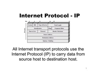
- 1. Internet Protocol - IP All Internet transport protocols use the Internet Protocol (IP) to carry data from source host to destination host. 1
- 2. IP provides several services: Addressing. IP headers contain 32-bit addresses which identify the sending and receiving hosts. These addresses are used by intermediate routers to select a path through the network for the packet. Fragmentation. IP packets may be split, or fragmented, into smaller packets. This permits a large packet to travel across a network which can only handle smaller packets. IP fragments and reassembles packets transparently. Packet timeouts. Each IP packet contains a Time To Live (TTL) field, which is decremented every time a router handles the packet. If TTL reaches zero, the packet is discarded, preventing packets from running in circles forever and flooding a network. Type of Service. IP supports traffic prioritization by allowing packets to be labeled with an abstract type of service. 2
- 3. IP Datagram Format 3
- 5. VERS - Version The version of the IP protocol. The current version is 4. 5 is experimental and 6 is IPng (see IP: The Next Generation (IPng)). The version of the IP protocol 5
- 6. LEN - Length The length of the IP header counted in 32- bit quantities. This does not include the data field. The length of the IP header 6
- 7. Type of Service The type of service is an indication of the quality of service requested for this IP datagram. quality of service?? 7
- 8. Type of Service - Precedence Is a measure of the nature and priority of this datagram: 000 Routine 001 Priority 010 Immediate 011 Flash 100 Flash override 101 Critical 110 Internetwork control 111 Network control 8
- 9. TOS - Type Of Service Specifies the type of service value: 1000 Minimize delay 0100 Maximize throughput 0010 Maximize reliability 0001 Minimize monetary cost 0000 Normal service A detailed description of the type of service can be found in the RFC 1349 9
- 10. MBZ - Must Be Zero Reserved for future use ("must be zero" unless participating in an Internet protocol experiment which makes use of this bit) 10
- 11. Total Length Total length of the IP datagram in bytes Maximum size is 64k because there are 16 bits for it That means a single IP datagram cannot be bigger than 65536 bytes including the header 11
- 12. Fragmentation Related Information The next 32 bits contain information related to fragmentation This information can be used to reassemble a fragmented IP datagram Fragmentation means that on its way a single IP datagram was broken into smaller IP datagrams because the intervening network was unable to carry the original datagram because it was too big 12
- 13. Why Fragment? When an IP datagram travels from one host to another, it can cross different physical networks. Physical networks have a maximum frame size, called the Maximum Transmission Unit (MTU), which limits the length of a datagram that can be placed in one physical frame. Therefore, a scheme has been put in place to fragment long IP datagrams into smaller ones, and to reassemble them at the destination host. IP requires that each link has an MTU of at least 68 bytes, so if any network provides a lower value than this, fragmentation and re-assembly must be implemented in the network interface layer in a way that is transparent to IP. 68 is the sum of the maximum IP header length of 60 bytes and the minimum possible length of data in a non-final fragment (8 bytes). IP implementations are not required to handle unfragmented datagrams larger than 576 bytes, but most implementations will handle larger values, typically slightly more than 8192 bytes or higher, and rarely less than 1500. 13
- 14. Why Fragment? Host - A in LAN -1 is commnicating with Host - B in LAN -2 using IP Host - A Host - B LAN -1 WAN -1 LAN - 2 Router Router Ethernet X.25 Ethernet -2 A B MTU = 1500 bytes MTU = 128 bytes MTU = 1500 bytes Router A has to perform fragmentation of IP datagrams when forwarding them from LAN-1 to WAN-1 14
- 15. Fragmentation Procedure An unfragmented datagram has all-zero fragmentation information. That is, the more fragments flag bit is zero and the fragment offset is zero. When fragmentation is to be done, the following steps are performed: 15
- 16. Fragmentation Procedure The DF flag bit is checked to see if fragmentation is allowed. If the bit is set, the datagram will be discarded and an error will be returned to the originator using ICMP. Based on the MTU value, the data field is split into two or more parts. All newly created data portions must have a length which is a multiple of 8 bytes, with the exception of the last data portion. 16
- 17. Fragmentation Example 17
- 18. Fragmentation Procedure - 2 All data portions are placed in IP datagrams. The header of these datagrams are copies of the original one, with some modifications: The more fragments flag bit is set in all fragments except the last. The fragment offset field in each is set to the location this data portion occupied in the original datagram, relative to the beginning of the original unfragmented datagram. The offset is measured in 8-byte units. If options were included in the original datagram, the high order bit of the option type byte determines whether or not they will be copied to all fragment datagrams or just to the first one. For instance, source route options have to be copied in all fragments and therefore they have this bit set. The header length field is of the new datagram is set. The total length field of the new datagram is set. The header checksum field is re-calculated. 18
- 19. Fragmentation Procedure - 3 Each of these fragmented datagrams is now forwarded as a normal IP datagram. IP handles each fragment independently, that is, the fragments may traverse different routers to the intended destination, and they may be subject to further fragmentation if they pass through networks that have smaller MTUs. 19
- 20. Reassembley Procedure At the destination host, the data has to be reassembled into one datagram. The identification field of the datagram was set by the sending host to a unique number (for the source host, within the limits imposed by the use of a 16-bit number). As fragmentation doesn't alter this field, incoming fragments at the receiving side can be identified, if this ID field is used together with the Source and Destination IP addresses in the datagram. The Protocol field is also to be checked for this identification. 20
- 21. Reassembley Procedure - 2 In order to reassemble the fragments, the receiving host allocates a buffer in storage as soon as the first fragment arrives. A timer routine is then started. When the timer timeouts and not all of the fragments have been received, the datagram is discarded. The initial value of this timer is called the IP datagram time-to-live (TTL) value. It is implementation dependent, and some implementations allow it to be configured; for example AIX Version 3.2 provides an ipfragttl option with a default value of 60 seconds. 21
- 22. Re-assembly Procedure - 3 When subsequent fragments of the datagram arrive, before the timer expires, the data is simply copied into the buffer storage, at the location indicated by the fragment offset field. As soon as all fragments have arrived, the complete original unfragmented datagram is restored, and processing continues, just as for unfragmented datagrams. 22
- 23. Fragmentation Fields Identification - A unique number assigned by the sender to aid in reassembling a fragmented datagram. Fragments of a datagram will have the same identification number. Fragment Offset - Used with fragmented datagrams, to aid in reassembly of the full datagram. The value is the number of 64-bit pieces (header bytes are not counted) that are contained in earlier fragments. In the first (or only) fragment, this value is always zero. 23
- 24. Flags Where: 0 Reserved, must be zero DF Don't Fragment: 0 means allow fragmentation 1 means do not allow fragmentation MF More Fragments: 0 means that this is the last fragment of this datagram, 1 means that this is not the last fragment. 24
- 25. Dealing with Failure in Re- assembly Re-assembly may fail if some fragments get lost Need to detect failure Re-assembly time out Assigned to first fragment to arrive If timeout expires before all fragments arrive, discard partial data Use packet lifetime (time to live in IP) If time to live runs out, kill partial data 25
- 26. TTL - Time To Live Specifies the time (in seconds) this datagram is allowed to travel. Each router where this datagram passes is supposed to subtract from this field its processing time for this datagram. Actually a router is able to process a datagram in less than 1 second; thus it will subtract one from this field, and the TTL becomes a hop-count metric rather than a time metric. When the value reaches zero, it is assumed that this datagram has been traveling in a closed loop and it is discarded. The initial value should be set by the higher- level protocol which creates the datagram. 26
- 27. Protocol- Protocol Number Indicates the higher-level protocol to which IP should deliver the data in this datagram. Some important values are: 0 Reserved 1 Internet Control Message Protocol (ICMP) 2 Internet Group Management Protocol (IGMP) 3 Gateway-to-Gateway Protocol (GGP) 4 IP (IP encapsulation) 5 Stream 6 Transmission Control (TCP) 8 Exterior Gateway Protocol (EGP) 9 Private Interior Routing Protocol 17 User Datagram (UDP) 89 Open Shortest Path First The full list can be found in STD 2 - Assigned Internet Numbers. 27
- 28. Header Checksum Is a checksum on the header only. It does not include the data. The checksum is calculated as the 16-bit one's complement of the one's complement sum of all 16-bit words in the header. For the purpose of this calculation, the checksum field is assumed to be zero. If the header checksum does not match the contents, the datagram is discarded because at least one bit in the header is corrupt, and the datagram may even have arrived at the wrong destination. 28
- 29. Options Various options regarding this datagram, including how to route it, how to identify it (security labeling), how to trace the places through which it passes, how •Security to time-stamp it for •Source routing •Route recording delay measurement, •Timestamping etc. 29
- 30. Options Options – Up to 40 bytes of option data added by source host or intermediate routers 1 byte Option id, followed by an optional 1 byte Option length, followed by Option data Padded to a multiple of 4 bytes 5 options currently defined Security – Security identifier Strict source routing – Complete route specified Loose source routing – List of required routers to pass through Record route – Each router appends its address to the list Timestamp – Each router appends address & timestamp stream id (used for voice) for reserved resources, 30
- 31. 31
- 32. IP Addresses To be able to identify a host on the internet, each host is assigned an address, the IP address, or Internet Address. The standards for IP addresses are described in RFC 1166 -- Internet Numbers. When the host is attached to more than one network, it is called multi-homed and it has one IP address for each network interface. 32
- 33. IP Addresses An IP Address is a 32 bit binary number. IP addresses are used by the IP protocol to uniquely identify a host on the internet. IP datagrams (the basic data packets exchanged between hosts) are transmitted by some physical network attached to the host and each IP datagram contains a source IP address and a destination IP address. 33
- 34. The Dotted Decimal Notation IP addresses are usually represented in a dotted decimal form (as the decimal representation of four 8-bit values concatenated with dots). For example 128.2.7.9 is an IP address with 128.2 being the network number and 7.9 being the host number. The rules used to divide an IP address into its network and host parts are explained below. 34
- 35. IP Address Example The binary format of the IP address 128.2.7.9 is: 10000000 00000010 00000111 00001001 IP address is made of four groups of decimal numbers between 0 - 255 separated by dots. Some of the numbers are special (like 0.0.0.0 or 255.255.255.255) and are used to designate the default gateway, a broadcast or multicast address, or some reserved numbers for the developers to play with. 35
- 36. Parts of an IP Address A part of the address designates the network numbers, and the remaining part designates the host number. So, we may say an IP address has the format NETWORK.HOST. The network number part of the IP address is centrally administered by the Internet Network Information Centre (the InterNIC) and is unique throughout the Internet. The IP address consists of a pair of numbers: IP address = <network number><host number> 36
- 37. Parts of an IP Address 37
- 38. Network Number Assignment One point to note about the split of an IP address into two parts is that this split also splits the responsibility for selecting the IP address into two parts. The network number is assigned by the InterNIC, and the host number by the authority which controls the network. The host number can be further subdivided: this division is controlled by the authority which owns the network, and not by the InterNIC. 38
- 39. IP Address Classes Traditionally, the conventions are that there are three main types of IP networks. Class A Class B Class C There are also: Class D Class E 39
- 40. Assigned Classes of Internet Addresses The first bits of the IP address specify how the rest of the address should be separated into its network and host part. The terms network address and netID are sometimes used instead of network number, but the formal term, used in RFC 1166, is network number. Similarly, the terms host address and hostID are sometimes used instead of host number. 40
- 41. Class A Network Addresses Class A networks use the first octet (8 bits) to designate the network, with the first (high- order) bit set to 0. The last three octets designate the host. So the Class A network addresses are 1.H.H.H to 127.H.H.H, where H is used to designate the host address octets. Class A addressing allows for 127 networks. Class A addresses use 7 bits for the network number giving 126 possible networks (out of every group of network and host numbers, two have a special meaning). The remaining 24 bits are used for the host number, so each networks can have up to 224 - minus 2 (16,777,214) hosts. 41
- 42. Class B Network Addresses Class B networks use two octets to designate the network and two to designate the host. The network part must begin with 10. The Class B networks are 128.x.H.H to 191.x.H.H, where x is any number between 0 and 255. Class B addresses use 14 bits for the network number, and 16 bits for the host number giving 16,382 Class B networks each with a maximum of 65534 hosts. 42
- 43. Class C Network Addresses Class C networks use three octets to designate the network and only one to designate the host. The network part begins with 110. The Class C networks are 192.x.x.H to 223.x.x.H, which allows for 2,097,152 networks. Class C addresses use 21 bits for the network number and 8 for the host number giving 2,097,150 networks each with up to 254 hosts. 43
- 44. IP Address Class’ Host Accommodation As you can see, there are very few Class A networks, but each of them can accommodate millions of hosts. A Class B network supports only 65,534 hosts, while Class C only 254 hosts (all 0 and 1 combinations are not allowed). 44
- 45. Other Address Classes There is also a Class D address (starts with 1110) used for multicasting, which is used to address groups of hosts in a limited area. Class E addresses are reserved for future use. Class E (1111) addresses are reserved for the nerds. 45
- 46. IPv4 - Problems The decision to standardize on a 32 bit address space meant that there were only 232 (4,294,967,296) IPv4 addresses available. During the early days of the Internet, the seemingly unlimited address space allowed IP addresses to be allocated based on requests rather than its actual need. 46
- 47. IPv4 - Problems The class A, B, and C octet boundaries were easy to understand and implement, but they did not foster efficient allocation of addresses. 47
- 48. IPv4 - Problems Class C, which supports 254 hosts, is too small. Class B, which supports 65534 hosts is too large. In the past, sites with several hundred hosts have been assigned as single Class B address rather than couple of Class C addresses. Unfortunately, this has resulted in a premature depletion of the Class B network address space. 48
- 49. Classless Inter-Domain Routing CIDR was officially documented in September 1993 in RFC 1517, 1518, 1519, 1520 Eliminates the traditional concept of Class A, B and C networks and replaces it with concept of “network prefix” CIDR supports the deployment of arbitrary size networks rather than the standard 8- bit, 16-bit, or 24 bit network numbers associated with classful addressing. 49
- 50. Classless Inter-Domain Routing Good News - CIDR is working. Bad News - Recent growth trends indicate that the number of Internet routes is beginning to increase at an exponential rate. 50
- 51. IP Configuration Parameters IP Address Subnet Mask Default Gateway DNS Server 51
- 52. How IP Operates at a Host 52
- 53. How IP Operates at a Host 53
- 54. What’s wrong with IP V4? Addressing Current addressing scheme allows for over 2 million networks, but most are Class “C” which are too small to be useful Most of the Class “B” networks have already been assigned Quality of Service IPv4 does not implement QoS functionality 54
- 55. What’s wrong with IP V4? Security IP packets can be easily snooped from the network No standard for authentication of the user to a server No standard for encryption of data in packets Packet Size Maximum packet size is 216 – 1 (65,535) May be too small considering newer, faster networks 55
- 56. IPv6 Solutions Addressing Addresses now 128 bits long (3.4 x 1034 addresses) Theoretically yields 665,570,793,348,866,943,898,599 IP addresses per square meter of the earth’s surface. Routing analysis shows practical values between 1564 and 3,911,873,538,269,506,102 IP addresses per square meter Address auto-configuration Quality of Service Flow control and QoS options allow for better connections of high bandwidth and high reliability applications 56
- 57. IPv6 Solutions Cont. Security Extension headers allow for standard encryption of data and standard authentication of users to hosts Packet Size Extension headers allow for larger packets 57