Simulink Implementation of Induction Machine Model – A Modular Approach
•
1 like•668 views

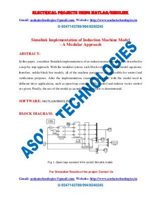
In this paper, a modular Simulink implementation of an induction machine model is described in a step-by-step approach. With the modular system, each block solves one of the model equations; therefore, unlike black box models, all of the machine parameters are accessible for control and verification purposes. After the implementation, examples are given with the model used in different drive applications, such as open-loop constant V/Hz control and indirect vector control are given. Finally, the use of the model as an induction generator is demonstrated.
Report
Share
Report
Share
Download to read offline

Recommended
Recommended
More Related Content
More from Asoka Technologies
More from Asoka Technologies (20)
A Variable DC Link based Novel Multilevel Inverter Topology for Low Voltage A...
A Variable DC Link based Novel Multilevel Inverter Topology for Low Voltage A...
A Simplified Space Vector Pulse-Width Modulation Scheme for Three-Phase Casca...
A Simplified Space Vector Pulse-Width Modulation Scheme for Three-Phase Casca...
A New Family of Step-up Hybrid Switched- Capacitor Integrated Multilevel Inve...
A New Family of Step-up Hybrid Switched- Capacitor Integrated Multilevel Inve...
A multi cell 21-level hybrid multilevel inverter synthesizes a reduced number...
A multi cell 21-level hybrid multilevel inverter synthesizes a reduced number...
A generalized multilevel inverter topology with reduction of total standing v...
A generalized multilevel inverter topology with reduction of total standing v...
Power Quality Improvement in Solar Fed Cascaded Multilevel Inverter with Outp...
Power Quality Improvement in Solar Fed Cascaded Multilevel Inverter with Outp...
Residential Community Load Management based on Optimal Design of Standalone H...
Residential Community Load Management based on Optimal Design of Standalone H...
Reliability evaluation of MPPT based interleaved boost converter for PV system
Reliability evaluation of MPPT based interleaved boost converter for PV system
Power Quality Improvement of Grid-Connected Photovoltaic Systems Using Trans-...
Power Quality Improvement of Grid-Connected Photovoltaic Systems Using Trans-...
Power optimisation scheme of induction motor using FLC for electric vehicle
Power optimisation scheme of induction motor using FLC for electric vehicle
Power Flow Control of Interconnected AC-DC Microgrids in Grid-Connected Hybri...
Power Flow Control of Interconnected AC-DC Microgrids in Grid-Connected Hybri...
Power flow control of hybrid micro grids using modified uipc
Power flow control of hybrid micro grids using modified uipc
Multifunctional grid tied pv system using modified klms control
Multifunctional grid tied pv system using modified klms control
Modelling and voltage control of the solar wind hybrid micro-grid with optimi...
Modelling and voltage control of the solar wind hybrid micro-grid with optimi...
Irradiance-adaptive PV Module Integrated Converter for High Efficiency and Po...
Irradiance-adaptive PV Module Integrated Converter for High Efficiency and Po...
Intelligent Power Sharing of DC Isolated Microgrid Based on Fuzzy Sliding Mod...
Intelligent Power Sharing of DC Isolated Microgrid Based on Fuzzy Sliding Mod...
Implementation of solar pv battery and diesel generator based electric vehic...
Implementation of solar pv battery and diesel generator based electric vehic...
Fuel cell integrated unified power quality conditioner for voltage and curren...
Fuel cell integrated unified power quality conditioner for voltage and curren...
Distributed incremental adaptive filter controlled grid interactive residenti...
Distributed incremental adaptive filter controlled grid interactive residenti...
Recently uploaded
This presentation was provided by William Mattingly of the Smithsonian Institution, during the third segment of the NISO training series "AI & Prompt Design." Session Three: Beginning Conversations, was held on April 18, 2024.Mattingly "AI & Prompt Design: The Basics of Prompt Design"
Mattingly "AI & Prompt Design: The Basics of Prompt Design"National Information Standards Organization (NISO)
God is a creative God Gen 1:1. All that He created was “good”, could also be translated “beautiful”. God created man in His own image Gen 1:27. Maths helps us discover the beauty that God has created in His world and, in turn, create beautiful designs to serve and enrich the lives of others.
Explore beautiful and ugly buildings. Mathematics helps us create beautiful d...
Explore beautiful and ugly buildings. Mathematics helps us create beautiful d...christianmathematics
Recently uploaded (20)
Call Girls in Dwarka Mor Delhi Contact Us 9654467111
Call Girls in Dwarka Mor Delhi Contact Us 9654467111
Mattingly "AI & Prompt Design: The Basics of Prompt Design"
Mattingly "AI & Prompt Design: The Basics of Prompt Design"
Kisan Call Centre - To harness potential of ICT in Agriculture by answer farm...
Kisan Call Centre - To harness potential of ICT in Agriculture by answer farm...
Beyond the EU: DORA and NIS 2 Directive's Global Impact
Beyond the EU: DORA and NIS 2 Directive's Global Impact
Z Score,T Score, Percential Rank and Box Plot Graph
Z Score,T Score, Percential Rank and Box Plot Graph
IGNOU MSCCFT and PGDCFT Exam Question Pattern: MCFT003 Counselling and Family...
IGNOU MSCCFT and PGDCFT Exam Question Pattern: MCFT003 Counselling and Family...
Explore beautiful and ugly buildings. Mathematics helps us create beautiful d...
Explore beautiful and ugly buildings. Mathematics helps us create beautiful d...
Web & Social Media Analytics Previous Year Question Paper.pdf
Web & Social Media Analytics Previous Year Question Paper.pdf
Simulink Implementation of Induction Machine Model – A Modular Approach
- 1. ELECTRICAL PROJECTS USING MATLAB/SIMULINK Gmail: asokatechnologies@gmail.com, Website: http://www.asokatechnologies.in 0-9347143789/9949240245 Simulink Implementation of Induction Machine Model – A Modular Approach For Simulation Results of the project Contact Us Gmail: asokatechnologies@gmail.com, Website: http://www.asokatechnologies.in 0-9347143789/9949240245 ABSTRACT: In this paper, a modular Simulink implementation of an induction machine model is described in a step-by-step approach. With the modular system, each block solves one of the model equations; therefore, unlike black box models, all of the machine parameters are accessible for control and verification purposes. After the implementation, examples are given with the model used in different drive applications, such as open-loop constant V/Hz control and indirect vector control are given. Finally, the use of the model as an induction generator is demonstrated. SOFTWARE: MATLAB/SIMULINK BLOCK DIAGRAM: Fig. 1. Open loop constant V/Hz control Simulink model.
- 2. ELECTRICAL PROJECTS USING MATLAB/SIMULINK Gmail: asokatechnologies@gmail.com, Website: http://www.asokatechnologies.in 0-9347143789/9949240245 EXPECTED SIMULATION RESULTS: Fig. 2. Simulation results – direct ac startup. For Simulation Results of the project Contact Us Gmail: asokatechnologies@gmail.com, Website: http://www.asokatechnologies.in 0-9347143789/9949240245
- 3. ELECTRICAL PROJECTS USING MATLAB/SIMULINK Gmail: asokatechnologies@gmail.com, Website: http://www.asokatechnologies.in 0-9347143789/9949240245 Fig. 3. Simulation results - open loop constant V/Hz control. For Simulation Results of the project Contact Us Gmail: asokatechnologies@gmail.com, Website: http://www.asokatechnologies.in 0-9347143789/9949240245
- 4. ELECTRICAL PROJECTS USING MATLAB/SIMULINK Gmail: asokatechnologies@gmail.com, Website: http://www.asokatechnologies.in 0-9347143789/9949240245 Fig. 4. Simulation results – indirect vector control. For Simulation Results of the project Contact Us Gmail: asokatechnologies@gmail.com, Website: http://www.asokatechnologies.in 0-9347143789/9949240245
- 5. ELECTRICAL PROJECTS USING MATLAB/SIMULINK Gmail: asokatechnologies@gmail.com, Website: http://www.asokatechnologies.in 0-9347143789/9949240245 For Simulation Results of the project Contact Us Gmail: asokatechnologies@gmail.com, Website: http://www.asokatechnologies.in 0-9347143789/9949240245 CONCLUSION: In this paper, implementation of a modular Simulink model for induction machine simulation has been introduced. Unlike most other induction machine model implementations, with this model, the user has access to all the internal variables for getting an insight into the machine operation. Any machine control algorithm can be simulated in the Simulink environment with this model without actually using estimators. If need be, when the estimators are developed, they can be verified using the signals in the machine model. The ease of implementing controls with this model is also demonstrated with several examples. Finally, the operation of the model to simulate both induction motors and generators has been shown so that there is no need for different models for different applications. REFERENCES: [1] M. L. de Aguiar, M. M. Cad, “The concept of complex transfer functions applied to the modeling of induction motors,” Power engineering Society Winter Meeting, 2000, pp. 387 -391. [2] A. Dumitrescu, D. Fodor, T. Jokinen, M. Rosu, S. Bucurencio, “Modeling and simulation of electric drive systems using Matlab/Simulink environments,” International Conference on Electric Machines and Drives (IEMD), 1999, pp. 451-453. [3] S. Wade, M. W. Dunnigan, B. W. Williams, “Modeling and simulation of induction machine vector control with rotor resistance identification,” IEEE Transactions on Power Electronics, vol. 12, no. 3, May 1997, pp. 495 -506. [4] H. Le-Huy, “Modeling and simulation of electrical drives using Matlab/Simulink and Power System Blockset,” The 27th Annual Conference of the IEEE Industrial Electronics Society (IECON'01), Denver/Colorado, pp. 1603-1611.