More Related Content
Similar to Install Note Juniper Netscreen Avaya Vsu Gateway And IP Softphones
Similar to Install Note Juniper Netscreen Avaya Vsu Gateway And IP Softphones (20)
Install Note Juniper Netscreen Avaya Vsu Gateway And IP Softphones
- 1. Configuring the Avaya™ VSU100R Gateway,
Netscreen 208 and 204 VPN Gateways, Avaya™ IP
Telephones and Softphones in a VPN Environment –
Issue 1.0
Abstract
These Application Notes describe the setup and configuration of devices in the following VPN
environments: Netscreen 208 VPN Gateway and Netscreen 204 Gateway, Netscreen 208 and
Avaya™ VSU100R Gateway.
CRK; Reviewed: Solution & Interoperability Test Lab Application Notes 1 of 26
WCH/MIC 11/25/2002 © 2002 Avaya Inc. All Rights Reserved. Netscreen-appl.doc
- 2. 1. Introduction
These Application Notes describe the setup and configuration of devices in the following VPN
environments: Netscreen 208 VPN Gateway and Netscreen 204 VPN Gateway, Netscreen 208
VPN Gateway and Avaya™ VSU100R Gateway. A detailed illustration of the configurations
tested along with a list of test equipment is contained herein.
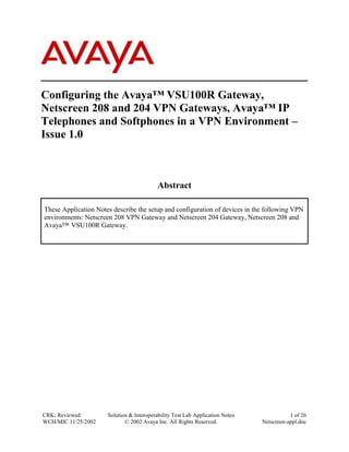
Figure 1 represents the sample network topology. In one configuration a site-to-site tunnel was
established between the Netscreen 208 and Avaya VSU100R for secure voice and data
transmissions. A second configuration replaced the VSU 100R with the Netscreen 204. The
Lucent AP 1000 was included in the test to accommodate the router functionality. A network
sniffer was used to verify that the packets going through the tunnels were encrypted.
Avaya™
VSU100R
Gateway
134.1.11.0/24
134.1.10.0/24
Lucent
AP 1000
Netscreen 204
Netscreen 208
.2 .1
.1 .2
192.16.5.0/24
.1
.1 .1
Avaya™
.3
P130
Avaya™ P333R Switch
Switch .2 .2
Endpoint-2
.1
.101
Endpoint-3 /
123
456
789
*8#
.101
IP Telephone-1 IPSec Client /
Avaya™ S8300 123
IP Softphone
456
.24 .23
789
Media Server /
*8#
.199 IP Telephone-2
Avaya™ G700
Media Gateway .2 Endpoint 1 134.1.12.0/24
Avaya™ IP600
Server
Digital
Telephone
Digital
Telephone
Trusted Zone A
192.16.6.0/24
Trusted Zone B
192.16.20.0/24
Figure 1: Network Configuration
The IP addresses in the table below were used during the verification (See Figure 1). The
Netscreen 204 and VSU100R were used in separate network configurations and used the same IP
address.
CRK; Reviewed: Solution & Interoperability Test Lab Application Notes 2 of 26
WCH/MIC 11/25/2002 © 2002 Avaya Inc. All Rights Reserved. Netscreen-appl.doc
- 3. Device Name Public IP Private IP Comments
Address Address
Netscreen 208 134.1.10.1 192.16.6.1
Netscreen 204 134.1.11.1 192.16.5.1
Avaya VSU100R Gateway 134.1.11.1 192.16.5.1
Avaya™ P330R Modular
Stackable Switch VLAN1 192.16.5.2 For Netscreen 204 private port.
VLAN2 192.16.20.1 Connection to IP600.
Avaya™ IP600 Internet Protocol
Communication Server
(CLAN) 192.16.20.23
(MedPro) 192.16.20.24 Default Gateway is 192.16.20.1
Avaya™ P330 Stack Processor 192.16.6.2 Default Gateway is 192.16.6.1
Media Gateway Processor (MGP) 192.16.6.3
VoIP Module 192.16.6.4
Media Processor (S8300) 192.16.6.5
Lucent Access Point 1000
Eth 10 134.1.10.2 For connection to Netscreen 208
Eth 11 134.1.11.2 For connection to Netscreen 204
Eth 12 134.1.12.1 For connection to IPSec Client
Netscreen IPSec Client / Avaya 134.1.12.2
IP Softphone
IP Telephone-1 192.16.6.101
IP Telephone-2 192.16.20.101
Endpoint-1 192.16.6.199
Endpoint-2 192.16.5.3
2. Equipment and Software Validated
The following software/firmware versions were used during the verification:
Equipment Version
Avaya IP600 Internet Protocol Communication Server R011c.01.0.060.0
Avaya™ S8300 Media Server with Avaya™ G700 Media R011x.01.0.060.4
Gateway
Avaya VSU100R Gateway 3.2.15
Avaya™ P330R modular Stackable Switch 3.9.1
Avaya™ P130 Workgroup Ethernet Switch 2.5.3
Avaya™ IP Telephone(s) 1.6
Avaya™ IP Softphone(s) 3.2.3
Netscreen 208 VPN Gateway 3.1.0r5.0
Netscreen 204 VPN Gateway 3.1.0r5.0
Netscreen IPSec Client V5.0
Lucent AP 1000 2.5.0.R3.1 QVPN
CRK; Reviewed: Solution & Interoperability Test Lab Application Notes 3 of 26
WCH/MIC 11/25/2002 © 2002 Avaya Inc. All Rights Reserved. Netscreen-appl.doc
- 4. Equipment Version
HP Internet Advisor (Sniffer) -
3. Configuring the Netscreen 208 / 204 VPN Gateway
The basic administration task order is as follows:
1) Set up Interfaces (Trusted and Untrusted)
2) Set up Routing Tables
3) Set up IP Address Zone
4) Set up IP Address Zone Group
5) Set up VPN
6) Set up Policy
Step Description
Set up Interfaces
Select System ! Interfaces from the main menu and click the Physical tab.
1
Normally, Ethernet 1 is designated for the trusted network and Ethernet 3 for the
untrusted network.
Click Edit on Ethernet 1 to configure the trusted interface.
Provide the following information:
IP Address= 192.16.6.1
Netmask= 255.255.255.0
Manager IP = 192.16.6.254 (This is the manager IP address that can be accessed
through the web).
Zone Name = Trust
Click Save.
CRK; Reviewed: Solution & Interoperability Test Lab Application Notes 4 of 26
WCH/MIC 11/25/2002 © 2002 Avaya Inc. All Rights Reserved. Netscreen-appl.doc
- 5. Step Description
Click Edit on Ethernet 3 to configure the untrusted interface.
Provide the following information:
IP Address= 134.1.10.1
Netmask= 255.255.255.0
Zone Name = Untrust
Click Save
CRK; Reviewed: Solution & Interoperability Test Lab Application Notes 5 of 26
WCH/MIC 11/25/2002 © 2002 Avaya Inc. All Rights Reserved. Netscreen-appl.doc
- 6. Step Description
Set up Routing Table
Select Network ! Routing on the main menu and click the Routing Table tab.
2
Two static routes were added.
1) Create an untrust Virtual router (untrust-vr) - All the untrusted traffic will be sent
to the Ethernet3 interface.
2) Create a trust Virtual Router (trust-vr) – All the traffic from the trusted side will
be forwarded to the untrusted virtual router.
Set up IP Address Zone
Select Lists ! Addresses from the main menu. Instead of creating new Zone
3
Names, the Zone Name (Untrust and Trust) will be used.
Click Address for the Untrust Zone.
Click New Address
CRK; Reviewed: Solution & Interoperability Test Lab Application Notes 6 of 26
WCH/MIC 11/25/2002 © 2002 Avaya Inc. All Rights Reserved. Netscreen-appl.doc
- 7. Step Description
Two IP Address groups were created:
Address Name = Network-192.16.20.0
IP Address = 192.16.20.0
Netmask = 255.255.255.0
Click OK
Address Name = Network-192.16.5.0
IP Address = 192.16.5.0
Netmask = 255.255.255.0
Click OK
Click Address for the Trust Zone.
Click New Address
Provide the following information:
Address Name = Netscreen-208
IP Address = 192.16.6.0
Netmask = 255.255.255.0
Click OK
Set up IP Address Zone Group
4 The purpose of the IP Address Zone Group is to combine IP Address Zones into a
group. This feature is supported only when two Netscreen VPN devices are used.
Click Group for the Untrust Zone.
Click New Group
CRK; Reviewed: Solution & Interoperability Test Lab Application Notes 7 of 26
WCH/MIC 11/25/2002 © 2002 Avaya Inc. All Rights Reserved. Netscreen-appl.doc
- 8. Step Description
Provide the following information:
Group Name = UntrustedGroup
Move IP Address from the Available Member to the Group Member.
Set up VPN
Select Network ! VPNs on the main menu and click the P1 Proposal tab.
5
Click New Phase 1 Proposal and provide the following information:
Name = Phase1-208-204
Authentication Method = Preshare
DH Group = Group 1
Encryption Algorithm = 3DES-CBC
Hash Algorithm = SHA-1
Lifetime = 1day
Click OK
Select Network ! VPNs on the main menu and click the P2 Proposal tab.
CRK; Reviewed: Solution & Interoperability Test Lab Application Notes 8 of 26
WCH/MIC 11/25/2002 © 2002 Avaya Inc. All Rights Reserved. Netscreen-appl.doc
- 9. Step Description
Click New Phase 2 Proposal and provide the following information:
Name = Phase2-208-204
PFS = NO-PFS
Check Encryption (ESP)
Encryption Algorithm = 3DES-CBC
Authentication Algorithm = SHA-1
Lifetime (In Time) = 1day
Lifetime (In Kbytes) = 1,000,000
Click OK
Select Network ! VPNs on the main menu and click the Gateway (P1) tab.
Click New Remote Tunnel Gateway and provide the following information:
Gateway Name = Netscreen204
Static IP Address = 134.1.11.1
Mode (Initiator) = Main
Outgoing Interface = Ethernet3
Phase 1 Proposal = Phase1-208-204
Preshared Key = 01234567890123456789
Click OK
CRK; Reviewed: Solution & Interoperability Test Lab Application Notes 9 of 26
WCH/MIC 11/25/2002 © 2002 Avaya Inc. All Rights Reserved. Netscreen-appl.doc
- 10. Step Description
Select Network ! VPNs on the main menu and click the AutoKey (P2) tab.
Click New AutoKey IKE Entry and provide the following information:
Name = VPN-208-204
Remote Gateway Tunnel = Netscreen204
Phase 2 Proposal = Phase2-208-204
Bind to = Tunnel Zone & Untrust-Tun
Click OK
Setup Policy
CRK; Reviewed: Solution & Interoperability Test Lab Application Notes 10 of 26
WCH/MIC 11/25/2002 © 2002 Avaya Inc. All Rights Reserved. Netscreen-appl.doc
- 11. Step Description
Select Network ! Policies on the main menu. The following screen illustrates all
6
policies used.
Select following information:
From Zone = Trust
To Zone = Untrust
Click New Policy and provide the following information:
Source Address = Netscreen-208
Destination Address = Network-192.16.20.0
Service = ANY
NAT = Off
Action = Tunnel
VPN Tunnel = VPN-208-204
Select Modify matching VPN policy
Logging = Enable
Click OK
CRK; Reviewed: Solution & Interoperability Test Lab Application Notes 11 of 26
WCH/MIC 11/25/2002 © 2002 Avaya Inc. All Rights Reserved. Netscreen-appl.doc
- 12. Step Description
Select following information:
From Zone = Untrust
To Zone = Trust
Click New Policy and provide the following information:
Source Address = Network-192.16.20.0
Destination Address = Netscreen-208
Service = ANY
NAT = Off
Action = Tunnel
VPN Tunnel = VPN-208-204
Select Modify matching VPN policy
Logging = Enable
Click OK
CRK; Reviewed: Solution & Interoperability Test Lab Application Notes 12 of 26
WCH/MIC 11/25/2002 © 2002 Avaya Inc. All Rights Reserved. Netscreen-appl.doc
- 13. Step Description
4. Configuring the Avaya VSU100R Gateway
Step Description
Connect to VSU
1 Using a null modem cable, connect the VSU 100R Gateway to the PC
2 Start a HyperTerminal session to the VSU 100R Gateway
Bits per second 9600
Data bits 8
Parity None
Stop bits 1
Flow control None
3 Enter VSU console password defined during initial use of the VSU.
Reset the VSU
4 From the main console menu
Select 1 - Configuration
Select 6 - Flush Configuration
Enter password – VSU console password
Do you really want to flush all configurations? [yn] y
Reboot required to complete the flush. Do you really want to reboot? [yn] y
Run Quick Setup
5 From the main console menu
CRK; Reviewed: Solution & Interoperability Test Lab Application Notes 13 of 26
WCH/MIC 11/25/2002 © 2002 Avaya Inc. All Rights Reserved. Netscreen-appl.doc
- 14. Step Description
Enter password – VSU console password
Select 5 – Quick Setup and enter the following:
IP Address 134.1.11.1
IP Mask 255.255.255.0
Do you want a secondary IP address on this unit? [yn] y
IP Address 192.16.5.1
IP Mask 255.255.255.0
Reboot Now? [yn] y
Step Description
Launch VPNmanager
From the Start menu, select Start ! VPNWare3 ! VPNmanager 3.1 Console
1
2 From the VPNmanager Login window
Enter the User Name and Password
Choose VPNmanager Server 192.16.5.3
Click the Connect button
Create a VSU domain
3 From the VPNmanager: No Domain opened window
Select VPN Domain -> New from the pull-down menu
Enter the Name for the new domain, i.e., Avaya
Click the Apply button
4 From the VPNmanager: Avaya window
Click the Config button
Create a VSU (VSU100R)
5 From the Configuration Console window
Select Edit ! New Object ! VSU from the pull-down menu
6 From the VSU Setup Wizard popup
Enter the new VSU name, i.e., VSU100R
Click Next
Choose New VSU Setup
Click Next
Choose IP Address
Enter 134.1.11.1 (Primary IP Address of the VSU)
Enter 192.16.5.1(Secondary IP address of the VSU)
Enter 255.255.255.0 (Secondary IP Mask)
Click Next
Click Deny all non VPN traffic
Click Static Route Config
Click Static Route Add…
CRK; Reviewed: Solution & Interoperability Test Lab Application Notes 14 of 26
WCH/MIC 11/25/2002 © 2002 Avaya Inc. All Rights Reserved. Netscreen-appl.doc
- 15. Step Description
Enter IP Address of Next Hop: 192.16.5.2
Click Add to List
Click Next
Enter Network IP address 192.16.20.0
Enter Mask 255.255.255.0
Click Add to List
Click Finished
Click Static Route OK
Click VSU Setup Wizard Next
Select Setup Now
Click Finished
When prompted, enter superuser user name and password
Click Save button (highlighted in yellow) in the Configuration Console
Click Update VSUs button in the Configuration Console
Create an IP Group
7 From the Configuration Console window
Select Edit ! New Object ! IPGroup from the pull-down menu
8 From the New IP Group popup
Enter the name of the IP Group, i.e., Network for VSU100
Click Apply
Enter the name of the IP Group, i.e., Network for Netscreen208
Click Apply
Click Close
9 Select Network for VSU100 from the Configuration Console window.
Click IP Group Add…
From the Add IPGroup Members popup, enter
New IP Network 192.16.5.0
New IP Mask 255.255.255.0
Click Apply
New IP Network 192.16.20.0
New IP Mask 255.255.255.0
Click Apply
Click Close
Click on the Associate this group with VSU list
Select VSU100R in place of Extranet device
Select Network for Netscreen208 from the Configuration Console window
Click IP Group Add…
From the Add IPGroup Members popup, enter
New IP Network 192.16.6.0
New IP Mask 255.255.255.0
Click Apply
Click Close
Click on the Associate this group with VSU list
CRK; Reviewed: Solution & Interoperability Test Lab Application Notes 15 of 26
WCH/MIC 11/25/2002 © 2002 Avaya Inc. All Rights Reserved. Netscreen-appl.doc
- 16. Step Description
Select Extranet device
Click Save (yellow button)
Click Update VSUs
Create a VPN
10 From the Configuration Console window
Select Edit ! New Object ! VPN from the pull-down menu
From the New VPN popup, enter
New VPN Name Netscreen-VSU
VPN Type IKE
Click Apply
Click Close
Select General tab
Click Preshared Secret
Check Enable VPN checkbox
Select Members – IP Groups tab
Move Network for VSU100 and Network for Netscreen208 from Available to
Members column
Select the Security (IKE) tab and choose the parameters
Select the Security (IPSec) tab and choose the parameters
Click Save (yellow button)
Click Update VSU
Close Configuration Console window
5. Configuring the Netscreen IPSec Client
This section presents the Netscreen IPSec client setup. The setup consists of two configuration
sections.
On the Netscreen VPN Gateway:
• Set up User
• Set up User Network
• Set up Phase 1
• Set up Phase 2
• Set up Dynamic IP (DIP)
• Set up Policy
On the IPSec Client:
• Set up Client Connection Parameters
• Set up Phase 1 Proposal
• Set up Phase 2 Proposal
Step Description
Configuring Netscreen VPN Gateway
Create a user by selecting Lists ! Users.
1
Click New Auth/IKE/L2TP User.
CRK; Reviewed: Solution & Interoperability Test Lab Application Notes 16 of 26
WCH/MIC 11/25/2002 © 2002 Avaya Inc. All Rights Reserved. Netscreen-appl.doc
- 17. Step Description
Provide the following information:
User Name = Celia
User Group = None
Status = Enable
Check IKE User
Check Simple Identity
IKE Identity = 134.1.12.2
Click OK
Create a user network by selecting Lists ! Addresses.
2
Click Address for the Untrust Zone.
Click New Address
The following IP address was created for a user:
Address Name = Network-Celia
IP Address = 192.16.12.2
Netmask = 255.255.255.0
Click OK
CRK; Reviewed: Solution & Interoperability Test Lab Application Notes 17 of 26
WCH/MIC 11/25/2002 © 2002 Avaya Inc. All Rights Reserved. Netscreen-appl.doc
- 18. Step Description
Create a gateway by selecting Network ! VPNs.
3
Click Gateway (P1) tab.
Click New Remote Tunnel Gateway.
Provide the following information:
Gateway Name = Gateway-Celia
Check Dialup User
User/Group = Dialup User – Celia
Mode = Aggressive
Outgoing Interface = Ethernet 3
Phase 1 Proposal = pre-g2-3des-md5
Preshared Key = 1234567890
Click OK
Create an AutoKey (P2) by selecting Network ! VPNs.
4
Click the AutoKey (P2) tab.
Click New AutoKey IKE Entry.
Provide the following information:
Name = Celia’s tunnel
Remote Gateway Tunnel = Gateway-Celia
Phase 2 Proposal = nopfs-esp-3des-md5
VPN Monitor = Enable
Click OK
CRK; Reviewed: Solution & Interoperability Test Lab Application Notes 18 of 26
WCH/MIC 11/25/2002 © 2002 Avaya Inc. All Rights Reserved. Netscreen-appl.doc
- 19. Step Description
!
5 Create a Dynamic IP (DIP) group from the Interfaces menu by selecting System!
Interfaces.
Click DIP on Interface 1 (Trust)
Provide the following information:
ID = 10 (can be any number as long as within the range)
Start = 192.16.6.170
End = 192.16.6.179
Click OK
Create a policy for the client by selecting Network ! Policies.
6
Select From Zone = Untrust
To Zone = Trust
Click New Policy
Provide the following information:
Source Address = Dialup VPN
Destination Address = Netscreen208
Service = ANY
CRK; Reviewed: Solution & Interoperability Test Lab Application Notes 19 of 26
WCH/MIC 11/25/2002 © 2002 Avaya Inc. All Rights Reserved. Netscreen-appl.doc
- 20. Step Description
NAT = ON
Click DIP ON
Select 10 (192.16.6.170 – 192.16.6.179)/Fixed
Action = Tunnel
VPN Tunnel = Celia’s Tunnel
Configuring IPSec Client
! ! !
7 Select Start!Programs!Netscreen-Remote!Security Policy Editor.
Rename the New Connection to Celia.
Provide the following information:
Connection Security = Secure
ID Type = IP Subnet
Subnet = 192.16.6.0
Mask = 255.255.255.0
Check Connect using Secure Gateway Tunnel.
ID Type = IP Address & 134.1.10.1
CRK; Reviewed: Solution & Interoperability Test Lab Application Notes 20 of 26
WCH/MIC 11/25/2002 © 2002 Avaya Inc. All Rights Reserved. Netscreen-appl.doc
- 21. Step Description
8 Click My Identity
Select Pre-Shared Key for Certificate.
ID Type = IP Address
9 Enter the Pre-Shared Key that matches with the VPN Gateway.
Click OK
CRK; Reviewed: Solution & Interoperability Test Lab Application Notes 21 of 26
WCH/MIC 11/25/2002 © 2002 Avaya Inc. All Rights Reserved. Netscreen-appl.doc
- 22. Step Description
10 Click Security Policy and select Aggressive Mode.
11 Select Create New Proposal for Proposal 1.
12 From the Proposal 1 menu, provide the following information:
CRK; Reviewed: Solution & Interoperability Test Lab Application Notes 22 of 26
WCH/MIC 11/25/2002 © 2002 Avaya Inc. All Rights Reserved. Netscreen-appl.doc
- 23. Step Description
Encrypt Alg = Triple DES
Hash Alg = MD5
SA Life = 28800 seconds
Key Group = D-H Group 2
13 Provide the following information for the Phase 2 Proposal:
SA Life = 3600 Seconds
Compression = None
Encrypt Alg = Triple DES
Hash Alg = MD5
Encapsulation = Tunnel
14 For a tunnel to be established, some traffic (Ping, WEB,..) has to be initiated.
Ping 192.16.6.X, and the tunnel will be negotiated between client and the VPN
Gateway, and the tunnel will come up.
CRK; Reviewed: Solution & Interoperability Test Lab Application Notes 23 of 26
WCH/MIC 11/25/2002 © 2002 Avaya Inc. All Rights Reserved. Netscreen-appl.doc
- 24. Step Description
6. Configuring the Avaya IP Softphone
Step Description
•
1. Start the IP Softphone by double-clicking the IP Softphone icon.
•
2. From the <Login> window, enter the following information:
o Extension 40701
o Password 1234
o Server Address 192.16.6.5 (S8300 Processor Address)
o Bandwidth Setup Local Area Network
• Click Login
Verify calls can be placed
•
3. From the <Avaya IP Softphone – 40701> window, enter the following
information:
o Extension 40601 (IP Telephone Set extension)
• Press Return
The extension (x40601) will ring. When answered, the call is established between
the IP Softphone (x40701) and the IP Telephone extension (x40601).
7. Configuring the Avaya IP Telephone-2 manually.
Step Description
•
1. During the normal start up process of the IP Telephone
o Press the star key (*) when prompted, OR
o While the IP Telephone is on-hook and idle, press Mute 2337# to
access the address information programming.
•
2. From the keypad
o Enter the IP Address of phone 192.16.6.101 followed by pound (#).
o Enter the IP address of the gatekeeper/call server (C-LAN board)
192.16.6.23 followed by pound (#).
o Enter Port number 1719 followed by pound (#).
o Enter IP address of Gateway/router 192.16.6.1 followed by pound (#).
CRK; Reviewed: Solution & Interoperability Test Lab Application Notes 24 of 26
WCH/MIC 11/25/2002 © 2002 Avaya Inc. All Rights Reserved. Netscreen-appl.doc
- 25. o Enter subnet mask of Gateway/router 255.255.255.0 followed by pound (#).
o Press pound (#) to save changes or star (*) to discard changes.
8. Conclusion
Avaya™ IP600 Server, Avaya™ S8300 Media Server, and Avaya™ IP Telephones can be used
in VPN environments. The tunnel configuration for the Netscreen 208/204 and Avaya™ VSU
100R Gateways is easy and reliable. The Application Notes illustrate how to configure Avaya IP
Telephones and Softphones, and Avaya and Netscreen VPN Gateways. These configurations
can be used by remote workers, traveling associates or between main and satellite offices in need
of the type of security provided by VPNs.
CRK; Reviewed: Solution & Interoperability Test Lab Application Notes 25 of 26
WCH/MIC 11/25/2002 © 2002 Avaya Inc. All Rights Reserved. Netscreen-appl.doc
- 26. © 2002 Avaya Inc. All The Rights Reserved.
Avaya and the Avaya Logo are trademarks of Avaya Inc. All trademarks identified by ® and ™
are registered trademarks or trademarks, respectively, of Avaya Inc. All other trademarks are the
property of their respective owners. The information provided in these Application Notes is
subject to change without notice. The configurations, technical data, and recommendations
provided in these Application Notes are believed to be accurate and dependable, but are
presented without express or implied warranty. Users are responsible for their application of any
products specified in these Application Notes.
Please e-mail any questions or comments pertaining to these Application Notes along with the
full title and filename, located in the lower the right corner, directly to the Avaya Solution &
Interoperability Test Lab at interoplabnotes@list.avaya.com
CRK; Reviewed: Solution & Interoperability Test Lab Application Notes 26 of 26
WCH/MIC 11/25/2002 © 2002 Avaya Inc. All Rights Reserved. Netscreen-appl.doc