

Recomendados
Más contenido relacionado
La actualidad más candente
La actualidad más candente (20)
Destacado
Destacado (20)
Similar a Sensor de pressão de pneu
Similar a Sensor de pressão de pneu (20)
Sensor de pressão de pneu
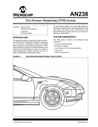
- 1. 2004 Microchip Technology Inc. DS00238B-page 1 AN238 INTRODUCTION This document explains a typical tire pressure monitor- ing (TPM) system specifically intended for automotive use. It serves as a reference to design a real-world system based on various Microchip products. A TPM system primarily monitors the internal temperature and pressure of an automobile's tire. There is a variety of system approaches to follow, although this one is a rather comprehensive auto-location system. An auto-location system can dynamically detect the position of a specific sensor, which is useful when tires are rotated. The heart of the TPM system is the Sensor/Transmitter (S/TX) device and it is based on Microchip's rfPIC12F675. SYSTEM COMPONENTS The TPM system consists of the following major component. • Sensor/Transmitter Device • RF Receiver Module • Low Frequency (LF) Commander Device • Control Unit • Pressure Vessel (Tire) FIGURE 1: TIRE PRESSURE MONITORING (TPM) SYSTEM Authors: Ruan Lourens Microchip Technology Inc. Curtis Kell Kell Laboratories Tire Pressure Monitoring (TPM) System
- 2. AN238 DS00238B-page 2 2004 Microchip Technology Inc. Sensor/Transmitter (S/TX) Device There are typically five S/TX units per vehicle, one per wheel, and the spare tire. Each unit has a unique serial number enabling the system to distinguish between each tire. When mounted within a vehicle tire, the S/TX periodically measures internal tire pressure, tempera- ture and battery condition. It then sends a RF signal composed of the measured information to a central receiver. The device described in this document is based on Microchip's rfPIC12F675 and the pressure and temperature sensing is performed by the Sensonor SP-13, a sensor IC (www.sensonor.com). The unit is also equipped with a LF receiver unit, used to commu- nicate to the S/TX device and to enable it from a Sleep state. RF Receiver Module A central RF receiver module receives transmissions from the individual S/TX devices. The receiver can also be used as a remote keyless entry receiver, saving on overall system cost. The design of the RF receiver module falls beyond the intent of this document. A functional RF receiver module is assumed. LF Commander Device The LF commander is designed to send specific commands to the S/TX unit via a 125 kHz ASK modu- lated signal. The LF link communicates over a short distance (1 meter or less), thus making it capable of communicating with the wheel in its immediate range. LF magnetic communications is well suited for sending commands to the S/TX devices. These commands, when received by the S/TX device, instruct it to carry out specific tasks. Control Unit The control unit is responsible for initiating communica- tions, interpreting received data and reporting the relevant information back to the vehicle. The unit will only be treated from a system overview perspective. Pressure Vessel The pressure vessels (tires) are the measurement subjects, with pressure and temperature values measured and reported. TPM Sensor/Transmitter TECHNICAL SPECIFICATIONS • Modulation Format: ASK • Operating Voltage: 2.5-3.6V • Low Voltage Alert Threshold: 2.5V • Quiescent Current: TBD RF Specific: • Transmit Frequency: 315 MHz • Transmit Interval: 60, 15 or 5 seconds (LF selectable) • Power Output: +9 dBm into 50 Ω load • Operating Current – Transmit: 12.5 mA at max RF power LF Specific: • Input Frequency: 125 kHz • Input Sensitivity: TBD Pressure Sensor Specific: • Pressure Sensor Range: 50-637 kPa absolute • Temperature Sensor Range: -40–125°C The schematic for the TPM S/TX is shown in Appendix A: “Schematics”. THEORY OF OPERATION The S/TX device comprises two integrated circuits: • Microchip’s rfPIC12F675 MCU/RF transmitter IC • Sensonor SP-13 (pressure, temperature and low-voltage sensor IC) In addition, the S/TX also includes LF input circuitry. This circuitry allows the S/TX device to receive special commands via the LF link. Refer to Appendix A: “Schematics” for additional circuit detail. rfPIC12F675 Transmitter IC The rfPICTM , based on the PIC12F675, was chosen as the heart of the S/TX for several reasons. First, the PIC12FXXX series of microcontrollers are widely used for transmitter applications and millions of PICmicro® microcontroller devices are currently used in transmit- ter applications today. Second, this device features an internal RC oscillator, thereby reducing the external component count which, directly reduces module cost as well as circuit board size. Third, this device includes the RF transmitter circuitry, which again reduces exter- nal component count, cost and overall size of the circuit board. The rfPIC12F675 also has an internal compara- tor which plays an important role in decoding the infor- mation from the LF link. The internal comparator helps reduce overall part count, thereby further reducing module cost and circuit board size. Lastly, the rfPIC12F675 features a 10-bit Analog-to-Digital converter, allowing the designer to use analog output pressure sensors. The rfPIC performs three functions. It monitors the data line from the SP-13 sensor IC and from the LF input, and assembles and transmits a RF message at periodic intervals.
- 3. 2004 Microchip Technology Inc. DS00238B-page 3 AN238 After application of power, the rfPIC executes an initial- ization procedure and goes into a Sleep mode until a state change is detected on either the SP-13 data line or the LF input. Either of these inputs generates a wake-up, causing the rfPIC to transition into the Run mode. If the wake-up was generated by the SP-13, the rfPIC reads the incoming data, assembles the data into an appropriate message, and transmits the message via the RF transmitter. Once the RF message is sent, the rfPIC reenters the Sleep mode. If the wake-up was generated by the LF input, the rfPIC interprets the LF message, executes the command and then reenters the Sleep mode. RF Circuitry The PLL style transmitter within the rfPIC requires minimum external components to complete the RF transmitter. The fundamental frequency of the transmit- ter is determined by Y1. To derive the appropriate crystal frequency, simply divide the desired transmit frequency by 32. For example, if the desired transmit frequency is 315 MHz, the crystal frequency is 9.84375 MHz. Loop antenna L3 is matched to the single-ended RF driver via C3 and C8, which also form the resonant tank. Refer to the “Matching Small Loop Antennas to rfPIC™ Devices” Application Note AN831 (DS00831) and “Designing Loop Antennas for the rfPIC12F675” Application Note AN868 (DS00868) for additional technical detail on selecting the appropriate component values for your RF application. Capacitor C4 is selected to provide decoupling for the 3V supply. Be sure the components selected for your application have a self-resonant frequency well above the desired transmit frequency. The filter formed by L2 and R6 further help decouple the high frequency energy from the rest of the circuitry. The R6 also de-Q’s the antenna. The output power of the transmitter circuit can be adjusted via R8, maximum power is obtained when it is left an open circuit. The transmit power can be changed per the “Power Select Resistor Select” table located in the “rfPIC12F675” Data Sheet (DS70091). This is also useful when trying to certify a product to FCC regulations. FIGURE 2: RF CIRCUITRY ANT PS rfPIC12F675 Y1 9.84375 MHZ C5 100 pF R6 220Ω Loop Antenna L2 120 nH C4 270 pF C8 22 pF C3 5 pF R8 N. I. XTAL L3
- 4. AN238 DS00238B-page 4 2004 Microchip Technology Inc. Sensonor SP-13 Sensor IC The SP-13 sensor IC performs several functions. It measures pressure, temperature, and generates a flag when the battery voltage drops below a predetermined threshold. The SP-13 has five unique modes: 1. Storage mode: If the pressure is below 1.5 bar, pressure is measured every 60 seconds but no data is sent. If the pressure increases above 1.5 bars, the component shifts into the Initial mode. 2. Initial mode: This mode occurs at power on or if the pressure increases above 1.5 bar from Storage mode. In this mode, pressure is measured every 0.85 seconds and data is sent every 0.85 seconds. This sequence is repeated 256 times. After the sequence is repeated 256 times, the device shifts into the Normal mode only if pressure is above 1.5 bar. If the pressure is below 1.5 bar, the device will shift into the Storage mode. 3. Normal mode: Pressure is measured every 3.4 seconds and data is transmitted every 60 seconds. If the measured pressure differs by more than 200 mbar from the reference taken every 60 seconds, the device enters a Pressure Alert mode. 4. Pressure Alert mode: It is the same measure- ment and transmitting pattern as the Initial mode. 5. High Temp Alert mode: If the temperature exceeds 120°C, the SP-13 device enters into the same measurement and transmitting pattern as the Initial mode. The SP-13 also includes a 32-bit identification number that is programmed into the device at the time of manufacture. This unique ID, when used by the central receiver, allows differentiation between S/TXs. Sensonor, as well as several other manufacturers, continue to offer enhanced pressure sensing devices of varying functionality. Therefore, it is recommended that a TPM developer thoroughly research the market prior to making a final pressure sensor selection. FIGURE 3: SENSONOR SP-13 SENSOR IC LF Input Circuitry The LF input is designed to receive and demodulate a 125 kHz signal and transform the received data into a specific command. The LF input circuit makes use of the internal comparator of the rfPIC, thereby reducing cost, module size and quiescent current. The LF input circuitry features a LC tank circuit that is tuned to 125 kHz. The LF sensing input comprises L1 and C11. L1 is specially designed by Coilcraft for this type of application. It provides good sensitivity in a compact package. A conventional coil could be used in its place, but overall circuit sensitivity or range would be reduced. Schottky diode D3 is used to clamp the voltage devel- oped across the LC tank to safe levels. The output of the LC tank circuit, after passing through current limit- ing resistor R5, is fed into the rfPIC comparator's neg- ative input. The comparator's positive input is configured as VREF through the rfPIC12F675’s VREF module. The output of the comparator is then fed into an envelope detector consisting of Schottky diode D2, capacitor C9 and resistor R3. C9 and R3 are selected to provide adequate filtering of the LF frequency with- out rounding the edges of the desired data signal. The output of the envelope detector is then fed directly into a port pin on the rfPIC and used to process the LF data. Without a limiting diode, the LF input circuit may be prone to being overdriven when strong LF fields are present. This can be seen when the LF commander device is in close proximity to the S/TX device. The envelope detection circuit can be abandoned to reduce cost, but doing so would require additional data extraction software. 1 2 3 4 5 6 7 8 9 10 11 12 13 14 VSS AVDD VDD TXBC TXD TXON GND5GND1 GND2 GND3 VSS REXT GND4 VSS U4 Pressure/Temperature Sensor IC x x +3V C10 0.01 µF R4 5.6 MΩ SP-13_SO rfPIC12F675 GP0
- 5. 2004 Microchip Technology Inc. DS00238B-page 5 AN238 FIGURE 4: LF CIRCUITRY Details of the LF transmission format and the specific commands can be found in the Section, "LF Com- mander". RF Transmission Format The encoding method used for this demonstration system is the 1/3-2/3 PWM format with TE (basic pulse element) time of 400 µs and a bit period of 3xTE or 1.2 ms. FIGURE 5: RF TRANSMISSION ENCODING METHOD Preamble: The preamble is a series of 31 logic ‘1’ bits followed by a single logic ‘0’ bit. The preamble allows the receiver to recognize the RF transmission as a valid S/TX message. The preamble also allows the receiver to synchronize to the RF message, thereby compen- sating for any oscillator inaccuracies within the transmitter. The system designer may vary the number of preamble bits based on system requirements. Longer preamble bit lengths may be appropriate where receiver quiescent current is an issue. Shorter preamble bit lengths may be appropriate where S/TX battery usage is a concern. In either case, it is purely a trade-off between receiver quiescent current and battery power consumed by the S/TX device. Transmitter ID: The 32 transmitter ID bits are used to uniquely identify each S/TX. A frame of 32 bits insures that there is a very low probability that any two S/TXs will have the same ID. Pressure: The pressure in kPa is obtained by multiply- ing the unsigned binary value of this byte by 2.5. Temperature: The temperature in degrees C is obtained by subtracting 40 from the unsigned value of byte 8. Battery: Bit 7 of this byte indicates the battery condition. A logic ‘1’ is considered normal while a logic ‘0’ indicates a low battery voltage. Status: This status byte contains the following informa- tion: Bits 0 and 1: Indicate operating state of sensor IC 00 = Initial or Storage mode 01 = Normal mode 10 = Pressure Alert mode 11 = Temperature Alert mode CRC (2 bytes): Implement according to CCITT standards. L1 D3C11 Schottky R5 10 kΩ rfPIC12F675_SSOP R3 51 kΩ C9 1000 pF LF OutLF In COUT GP3 CIN- D2 Schottky 220 pFInductor Bits Preamble 32 Transmitter ID 32 Pressure 8 Temperature 8 Battery 8 Status 8 CRC 16 TE TE TE Logic ‘1’ TE TE TE Logic ‘0’
- 6. AN238 DS00238B-page 6 2004 Microchip Technology Inc. LF Commander THEORY OF OPERATION The system proposed in this document is based on an auto-location system, enabling it to detect the position of a specific S/TX device. This requires a LF commander device at each wheel arc and possibly at the spare tire mounting position. Having a handheld LF commander unit can enable a lower cost system. Although, this would require that the system be manually relearned after a tire rotation, the S/TX device is able to detect tire rotation or some other system to engage data transmission. The LF commander device is capable of sending commands to the S/TX device via a LF transmission such as: • Enable RF transmissions • Disable RF transmissions • Transmit an immediate message • Transmit at 60-second intervals • Transmit at 15-second intervals • Transmit at 5-second intervals The LF commander unit is based on the PIC16F628 MCU device. Communication between the LF commander and the S/TX is accomplished via magnetic field. When the LF commander is transmitting a message, it is essentially creating a magnetic field by exciting a series LC circuit. The LC circuit is excited by the PICmicro's PWM port. This port is set up to gener- ate a 50% duty cycle at 125 kHz. The command data is then modulated on this 125 kHz signal in the form of ASK modulation. Functionally, this is accomplished by instructing the PICmicro to toggle the PWM port between 0% and 50% duty cycle at the rate of the data. LF TRANSMISSION FORMAT The encoding format used in the LF link is a 1/3 - 2/3 PWM format with 400 µs TE (basic pulse element). Selecting 400 µs TE or greater insures the magnetic field generated by the series LC circuit has adequate time to rise and decay, without requiring too much wave shaping of the recovered square wave in the S/TX circuitry. The transmission data format for the LF link is shown in Figure 6. FIGURE 6: LF TRANSMISSION ENCODING METHOD Preamble: The preamble is a series of 15 logic ‘1’ bits and 1 logic ‘0’ bit. This reduces the chance of the S/TX receiving erroneous data from electronic devices that generate strong 125 kHz fields. Computer CRT's and switching power supplies are examples of such devices. Command: These 8 bits of data contains the specific command that the S/TX is being asked to perform. Table 1 illustrates the various commands (MSB is left most column). TABLE 1: BIT FUNCTIONS Sum Check: Calculated by adding contents of the command byte with ‘10101010’. SUMMARY TPM use in the automotive industry is growing, driven by customer demand, improved safety, and possible compulsory-usage legislation. Microchip’s low-cost rfPIC devices are well suited for the application and help reduce the overall TPM system cost. The use of rfPIC based S/TX makes for a flexible solution that allows for the merging with existing systems such as security, PKE, RKE and more. Bits Function 01101101 Enable RF transmissions 10010010 Disable RF transmissions 10101010 Transmit an immediate RF message 10110110 Transmit at 60-second interval 11001100 Transmit at 15-second interval 11010011 Transmit at 5-second interval Bits Preamble 16 Command 8 Sum Check 8 TE TE TE Logic ‘1’ TE TE TE Logic ‘0’
- 7. 2004 Microchip Technology Inc. DS00238B-page 7 AN238 FIGURE 7: PHOTOGRAPH OF SENSOR/TRANSMITTER DEVICE
- 8. AN238 DS00238B-page 8 2004 Microchip Technology Inc. REFERENCE DOCUMENTS The following reference documents are available from Microchip's web site at www.microchip.com. 1. “Low Frequency Magnetic Transmitter Design” Application Note (AN232), DS00232; Microchip Technology Inc. 2. “Designing Loop Antennas for the rfPIC12F675” Application Note (AN868), DS00868; Microchip Technology Inc. 3. “Matching Small Loop Antennas to rfPIC Devices” Application Note (AN831), DS00831; Microchip Technology Inc. 4. “Magnetic Tuning of Resonant Resistors and Methods for Increasing Sensitivity” Application Note (AN832), DS00832; Microchip Technology Inc. 5. “Optimizing PLL Filters for the rfPIC12C509A and rfHCS362” Application Note (AN846), DS00846; Microchip Technology Inc. 6. “rfPIC12F675” Data Sheet, DS70091; Microchip Technology Inc. . Note: Microchip has a confidential Application Note on Magnetic Sensors, “Magnetic Tuning of Resonant Resistors and Meth- ods for Increasing Sensitivity” Application Note, DS00832. Contact Microchip for a Non-Disclosure Agreement in order to obtain this application note.
- 9. 2004 Microchip Technology Inc. DS00238B-page 9 AN238 APPENDIX A: SCHEMATICS FIGURE A-1: TPM SENSOR/TRANSMITTER SCHEMATIC R1 150Ω 1 2 3 4 5 6 7 8 9 1011 12 13 14 15 16 17 18 19 20 ANT VSSRF NC DATA_ASK DATA_FSK FSKOUT GP2/AN2/T0CKI/INT/COUT GP1/AN1/CIN-/ICSPCLK GP0/AN0/CIN+/ICSPDAT VSSVDD GP5/T1CKI/OSC1/CLKIN GP4/AN3/T1G/OSC2/CLKOUT GP3/MCLR/VPP RFXTAL RFENIN NC PS VDDRF VDDRF U1 rfPIC12F675_SSOP LF_FILTER_DATA ASK_DATA LF_IN SENSOR_DATA LF_RAW_DATA x x x BT1 +3V Y1 9.84375MHZ C1 0.01µF C2 270pF C5 100pFD1 LED R3 51kΩC9 1000pF R5 10kΩ LFInputCircuitry LFOut 1 2 3 4 5 6 78 9 10 11 12 13 14 VSS AVDD VDD TXBC TXD TXON GND5GND1 GND2 GND3 VSS REXT GND4 VSS U4 Pressure/TemperatureSensorIC x x +3V C10 0.01µF R4 5.6MΩSP-13_SO R6 220Ω R8 N.I. LoopAntenna D2 Schottky +3V x ASK_DATA L2 120nH C4 270pF C8 22pF C3 5pF L1 D3 C11 Schottky220pFInductor L3
- 10. AN238 DS00238B-page 10 2004 Microchip Technology Inc. NOTES:
- 11. 2004 Microchip Technology Inc. DS00238B-page 11 Information contained in this publication regarding device applications and the like is intended through suggestion only and may be superseded by updates. It is your responsibility to ensure that your application meets with your specifications. No representation or warranty is given and no liability is assumed by Microchip Technology Incorporated with respect to the accuracy or use of such information, or infringement of patents or other intellectual property rights arising from such use or otherwise. Use of Microchip’s products as critical components in life support systems is not authorized except with express written approval by Microchip. No licenses are conveyed, implicitly or otherwise, under any intellectual property rights. Trademarks The Microchip name and logo, the Microchip logo, Accuron, dsPIC, KEELOQ, MPLAB, PIC, PICmicro, PICSTART, PRO MATE and PowerSmart are registered trademarks of Microchip Technology Incorporated in the U.S.A. and other countries. AmpLab, FilterLab, microID, MXDEV, MXLAB, PICMASTER, SEEVAL, SmartShunt and The Embedded Control Solutions Company are registered trademarks of Microchip Technology Incorporated in the U.S.A. Application Maestro, dsPICDEM, dsPICDEM.net, dsPICworks, ECAN, ECONOMONITOR, FanSense, FlexROM, fuzzyLAB, In-Circuit Serial Programming, ICSP, ICEPIC, Migratable Memory, MPASM, MPLIB, MPLINK, MPSIM, PICkit, PICDEM, PICDEM.net, PICtail, PowerCal, PowerInfo, PowerMate, PowerTool, rfLAB, rfPIC, Select Mode, SmartSensor, SmartTel and Total Endurance are trademarks of Microchip Technology Incorporated in the U.S.A. and other countries. Serialized Quick Turn Programming (SQTP) is a service mark of Microchip Technology Incorporated in the U.S.A. All other trademarks mentioned herein are property of their respective companies. © 2004, Microchip Technology Incorporated, Printed in the U.S.A., All Rights Reserved. Printed on recycled paper. Note the following details of the code protection feature on Microchip devices: • Microchip products meet the specification contained in their particular Microchip Data Sheet. • Microchip believes that its family of products is one of the most secure families of its kind on the market today, when used in the intended manner and under normal conditions. • There are dishonest and possibly illegal methods used to breach the code protection feature. All of these methods, to our knowledge, require using the Microchip products in a manner outside the operating specifications contained in Microchip's Data Sheets. Most likely, the person doing so is engaged in theft of intellectual property. • Microchip is willing to work with the customer who is concerned about the integrity of their code. • Neither Microchip nor any other semiconductor manufacturer can guarantee the security of their code. Code protection does not mean that we are guaranteeing the product as “unbreakable.” Code protection is constantly evolving. We at Microchip are committed to continuously improving the code protection features of our products. Attempts to break Microchip’s code protection feature may be a violation of the Digital Millennium Copyright Act. If such acts allow unauthorized access to your software or other copyrighted work, you may have a right to sue for relief under that Act. Microchip received ISO/TS-16949:2002 quality system certification for its worldwide headquarters, design and wafer fabrication facilities in Chandler and Tempe, Arizona and Mountain View, California in October 2003. The Company’s quality system processes and procedures are for its PICmicro® 8-bit MCUs, KEELOQ® code hopping devices, Serial EEPROMs, microperipherals, nonvolatile memory and analog products. In addition, Microchip’s quality system for the design and manufacture of development systems is ISO 9001:2000 certified.
- 12. DS00238B-page 12 2004 Microchip Technology Inc. AMERICAS Corporate Office 2355 West Chandler Blvd. Chandler, AZ 85224-6199 Tel: 480-792-7200 Fax: 480-792-7277 Technical Support: 480-792-7627 Web Address: http://www.microchip.com Atlanta 3780 Mansell Road, Suite 130 Alpharetta, GA 30022 Tel: 770-640-0034 Fax: 770-640-0307 Boston 2 Lan Drive, Suite 120 Westford, MA 01886 Tel: 978-692-3848 Fax: 978-692-3821 Chicago 333 Pierce Road, Suite 180 Itasca, IL 60143 Tel: 630-285-0071 Fax: 630-285-0075 Dallas 4570 Westgrove Drive, Suite 160 Addison, TX 75001 Tel: 972-818-7423 Fax: 972-818-2924 Detroit Tri-Atria Office Building 32255 Northwestern Highway, Suite 190 Farmington Hills, MI 48334 Tel: 248-538-2250 Fax: 248-538-2260 Kokomo 2767 S. Albright Road Kokomo, IN 46902 Tel: 765-864-8360 Fax: 765-864-8387 Los Angeles 18201 Von Karman, Suite 1090 Irvine, CA 92612 Tel: 949-263-1888 Fax: 949-263-1338 San Jose 1300 Terra Bella Avenue Mountain View, CA 94043 Tel: 650-215-1444 Fax: 650-961-0286 Toronto 6285 Northam Drive, Suite 108 Mississauga, Ontario L4V 1X5, Canada Tel: 905-673-0699 Fax: 905-673-6509 ASIA/PACIFIC Australia Suite 22, 41 Rawson Street Epping 2121, NSW Australia Tel: 61-2-9868-6733 Fax: 61-2-9868-6755 China - Beijing Unit 706B Wan Tai Bei Hai Bldg. No. 6 Chaoyangmen Bei Str. Beijing, 100027, China Tel: 86-10-85282100 Fax: 86-10-85282104 China - Chengdu Rm. 2401-2402, 24th Floor, Ming Xing Financial Tower No. 88 TIDU Street Chengdu 610016, China Tel: 86-28-86766200 Fax: 86-28-86766599 China - Fuzhou Unit 28F, World Trade Plaza No. 71 Wusi Road Fuzhou 350001, China Tel: 86-591-7503506 Fax: 86-591-7503521 China - Hong Kong SAR Unit 901-6, Tower 2, Metroplaza 223 Hing Fong Road Kwai Fong, N.T., Hong Kong Tel: 852-2401-1200 Fax: 852-2401-3431 China - Shanghai Room 701, Bldg. B Far East International Plaza No. 317 Xian Xia Road Shanghai, 200051 Tel: 86-21-6275-5700 Fax: 86-21-6275-5060 China - Shenzhen Rm. 1812, 18/F, Building A, United Plaza No. 5022 Binhe Road, Futian District Shenzhen 518033, China Tel: 86-755-82901380 Fax: 86-755-8295-1393 China - Shunde Room 401, Hongjian Building, No. 2 Fengxiangnan Road, Ronggui Town, Shunde District, Foshan City, Guangdong 528303, China Tel: 86-757-28395507 Fax: 86-757-28395571 China - Qingdao Rm. B505A, Fullhope Plaza, No. 12 Hong Kong Central Rd. Qingdao 266071, China Tel: 86-532-5027355 Fax: 86-532-5027205 India Divyasree Chambers 1 Floor, Wing A (A3/A4) No. 11, O’Shaugnessey Road Bangalore, 560 025, India Tel: 91-80-2290061 Fax: 91-80-2290062 Japan Benex S-1 6F 3-18-20, Shinyokohama Kohoku-Ku, Yokohama-shi Kanagawa, 222-0033, Japan Tel: 81-45-471- 6166 Fax: 81-45-471-6122 Korea 168-1, Youngbo Bldg. 3 Floor Samsung-Dong, Kangnam-Ku Seoul, Korea 135-882 Tel: 82-2-554-7200 Fax: 82-2-558-5932 or 82-2-558-5934 Singapore 200 Middle Road #07-02 Prime Centre Singapore, 188980 Tel: 65-6334-8870 Fax: 65-6334-8850 Taiwan Kaohsiung Branch 30F - 1 No. 8 Min Chuan 2nd Road Kaohsiung 806, Taiwan Tel: 886-7-536-4818 Fax: 886-7-536-4803 Taiwan Taiwan Branch 11F-3, No. 207 Tung Hua North Road Taipei, 105, Taiwan Tel: 886-2-2717-7175 Fax: 886-2-2545-0139 EUROPE Austria Durisolstrasse 2 A-4600 Wels Austria Tel: 43-7242-2244-399 Fax: 43-7242-2244-393 Denmark Regus Business Centre Lautrup hoj 1-3 Ballerup DK-2750 Denmark Tel: 45-4420-9895 Fax: 45-4420-9910 France Parc d’Activite du Moulin de Massy 43 Rue du Saule Trapu Batiment A - ler Etage 91300 Massy, France Tel: 33-1-69-53-63-20 Fax: 33-1-69-30-90-79 Germany Steinheilstrasse 10 D-85737 Ismaning, Germany Tel: 49-89-627-144-0 Fax: 49-89-627-144-44 Italy Via Quasimodo, 12 20025 Legnano (MI) Milan, Italy Tel: 39-0331-742611 Fax: 39-0331-466781 Netherlands P. A. De Biesbosch 14 NL-5152 SC Drunen, Netherlands Tel: 31-416-690399 Fax: 31-416-690340 United Kingdom 505 Eskdale Road Winnersh Triangle Wokingham Berkshire, England RG41 5TU Tel: 44-118-921-5869 Fax: 44-118-921-5820 01/26/04 WORLDWIDE SALES AND SERVICE