Forensics Exhibit Illustrations
•
0 recomendaciones•322 vistas

This engineering forensics illustration presentation shows two cases I selected to show the use of both 3D and 2D to illustrated the consultants conclusions. The 3D illustrations allowed him to clearly show complex engineering concepts to a non-technical audience.

Recomendados
Más contenido relacionado
Similar a Forensics Exhibit Illustrations
Similar a Forensics Exhibit Illustrations (20)
Último
Último (20)
Forensics Exhibit Illustrations
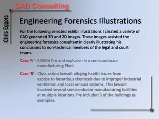
- 1. Engineering Forensics Illustrations For the following selected exhibit illustrations I created a variety of CAD generated 3D and 2D images. These images assisted the engineering forensics consultant in clearly illustrating his conclusions to non-technical members of the court and legal teams. Case ‘A’ - $500M fire and explosion in a semiconductor manufacturing Plant Case ‘B’ - Class action lawsuit alleging health issues from expose to hazardous chemicals due to improper industrial ventilation and local exhaust systems. This lawsuit involved several semiconductor manufacturing facilities at multiple locations. I’ve included 3 of the buildings as examples.
- 2. Case ‘A’ These selected exhibit illustrations were created from insurance photographs, engineering drawings, and the forensics consultant’s sketches. The use of 3D & 2D CAD allowed for the accurate recreation of this facility prior to the incident and to clearly illustrate the complete exhaust systems with the fire source and extent of system damage Software utilized: AutoCAD Architectural & Building Systems
- 3. Composite Exhaust System 3D IllustrationShows the routing of all process exhaust systems from the cleanroom to the scrubbers/fans on the roof. Acorn Consulting Services, LLC Client:
- 4. Acid/Toxic Exhaust System IllustrationShows the routing of acid/toxic exhaust system from the cleanroom to the scrubbers on the roof. The source of the fire was in this system and is outlined on the illustration. Acorn Consulting Services, LLC Client:
- 5. Acid/Toxic Exhaust System Damage IllustrationShows the routing of acid/toxic exhaust system from the cleanroom to the scrubbers on the roof. All equipment and exhaust duct damage shown in light gray. Acorn Consulting Services, LLC Client:
- 6. Return Air Building Level - Exhaust System Damage IllustrationShows the relation of the exhaust systems and the structure at the level the fire started. All equipment and exhaust duct damage shown in light gray. Acorn Consulting Services, LLC Client:
- 7. Return Air Building Level - Photo Location IllustrationShows the location and direction for each insurance company photo used to created all illustrations. Acorn Consulting Services, LLC Client:
- 8. Composite Exhibit Of Multiple Illustration Styles The 3D & 2D illustrations from the source of the fires were shown with a photograph as an example of the clarity the CAD illustrations offered. Acorn Consulting Services, LLC Client:
- 9. Enlarged 3D IllustrationShows more detail for the location of the fire source. This view places all interconnected process/support equipment and exhaust ducts associated with the fire. Both wire frame and solids modeling were used for this illustration. Acorn Consulting Services, LLC Client:
- 10. Alternate Enlarged 3D illustrationThis illustration is a simplified example of the prior one. The exhaust systems and process equipment have been shaded in color for additional clarity. Acorn Consulting Services, LLC Client:
- 11. Case ‘B’ - Building 1 The following selected exhibit Illustrations were created from engineering drawings from the time period of the case and the forensics consultant’s sketches. The plaintiff worked in two rooms within this building. Their legal team claimed the HVAC systems were simple and inadequate. The 2D plans clearly show that each of the suspect tools in these areas were exhausted and that each area had separate and sufficient HEPA filtered air supply. The sections show the interrelationship of the systems, work areas, and equipment. The 3D images allowed for a clearer illustration of the complex HVAC systems in a more familiar context for a non-technical audience. Acorn Consulting Services, LLC Client: Created with AutoCAD Architectural/Building Systems
- 12. Composite HVAC Systems 3D Illustration Shows all HVAC equipment and ducts for both rooms. Acorn Consulting Services, LLC Client:
- 13. 1st Floor Equipment And Exhaust Plan Shows all tools of concern in both rooms and which exhaust ducts they’re connected to. Acorn Consulting Services, LLC Client:
- 14. 1st Floor HVAC Ceiling Plan Shows HEPA filter coverage for both rooms. Acorn Consulting Services, LLC Client:
- 15. HVAC Mezzanine Level Plan Illustrates the supply/return air ducts for both rooms. Acorn Consulting Services, LLC Client:
- 16. HVAC Roof Plan Shows air conditioners, pre-filters, exhaust fans and related ductwork located on the roof for both rooms. Acorn Consulting Services, LLC Client:
- 17. Room ‘A’ HVAC3D Illustration Shows all HVAC ducts and process equipment for room ‘A’. Acorn Consulting Services, LLC Client:
- 18. Room ‘A’ Building Section Shows how the exhaust and supply/return air systems operate in the room and with the process equipment. Acorn Consulting Services, LLC Client:
- 19. Room ‘B’ Supply Air3D Illustration Shows all supply air ducts and process equipment for room ‘B’. Acorn Consulting Services, LLC Client:
- 20. Room ‘A’ Exhaust system3D & 2D Illustration The 3D illustration shows all exhaust ducts and process equipment for room ‘B’. The 2D illustration shows a section through the room to show the process equipment connected to the exhaust ducts. Acorn Consulting Services, LLC Client:
- 21. Room ‘B’ Building Section Shows how the exhaust and supply/return air systems operate with the process equipment in the room. Acorn Consulting Services, LLC Client:
- 22. Case ‘B’ - Building 2 The following selected exhibit Illustration examples were created from engineering drawings from the time period of the case, and forensics consultant’s sketches. The plaintiff in this building worked in multiple process bays adjacent to each other. These were illustrated together to show their relationship with the HVAC systems for each. The 2D plans clearly show the systems of each level. The sections show the interrelationship of the systems, work areas, and equipment. The 3D images allowed for a clearer illustration of the complex HVAC systems in a more familiar context for a non-technical audience. Acorn Consulting Services, LLC Client: Created with AutoCAD Architectural/Building Systems
- 23. Composite HVAC Systems 3D Illustration Showing all HVAC systems for the 4 cleanroom bays. Acorn Consulting Services, LLC Client:
- 24. HVAC Ceiling Plan Showing HEPA filter coverage and exhaust ducts for the cleanroom process and equipment service bays Acorn Consulting Services, LLC Client:
- 25. HVAC Roof Plan Showing the air handling equipment located on the roof for each cleanroom bay. Acorn Consulting Services, LLC Client:
- 26. Building Section Looking North Showing supply/return air and exhaust systems, work area and process equipment for the 4 cleanroom bays. Acorn Consulting Services, LLC Client:
- 27. Building Section Looking East Showing supply/return air and exhaust systems, work area and process equipment for the 4 cleanroom bays. Acorn Consulting Services, LLC Client:
- 28. 3D Process Bay Illustration Showing a typical work area. Acorn Consulting Services, LLC Client:
- 29. Case ‘B’ - Building 3 The following selected exhibit Illustration examples were created from engineering drawings from the time period of the case, and forensics consultant’s sketches. The use of 3D & 2D CAD allowed for the accurate time period recreation of this facility. The plaintiff in this building worked a few different areas in the cleanroom that are not adjoined. For this example the entire cleanroom is shown. The 2D plans clearly show the systems of each level. The sections show the interrelationship of the systems, work areas, and equipment. The 3D images allowed for a clearer illustration of the complex HVAC systems in a more familiar context for a non-technical audience. Acorn Consulting Services, LLC Client: Created with AutoCAD Architectural/Building Systems
- 30. Cleanroom Architectural 3D Illustration Showing all of the cleanroom with areas of interest outlined. Acorn Consulting Services, LLC Client:
- 31. Cleanroom Process Equipment Plan Showing all areas with process tools with areas of interest outlined. Acorn Consulting Services, LLC Client:
- 32. Cleanroom Process Exhaust Systems 3D Illustration Showing the complete cleanroom process exhaust layout with areas of interest outlined. Acorn Consulting Services, LLC Client:
- 33. Cleanroom Process Exhaust System Plan Showing the complete cleanroom process exhaust layout with areas of interest outlined. Acorn Consulting Services, LLC Client:
- 34. Cleanroom Supply Air System Plan Showing the complete cleanroom supply air with areas of interest outlined. Acorn Consulting Services, LLC Client:
- 35. HVAC Roof Plan Showing the location of the cleanroom air handlers and exhaust fans on the roof. Acorn Consulting Services, LLC Client:
- 36. Cleanroom Air Handlers - 3D Illustration Showing the air handlers with supply and makeup air ducts located on the roof. Acorn Consulting Services, LLC Client:
- 37. Building Section Showing supply/return air and exhaust systems, work area and process equipment for the 4 cleanroom bays. Acorn Consulting Services, LLC Client:
- 38. Air Handler Operational Diagram Showing how the supply, return and makeup air system equipment operates. Acorn Consulting Services, LLC Client:
- 39. Thank you for your interestcecadconsulting@cox.net