1362 1363 1352 1353 ball valve with elect and pneu actuator
•
1 recomendación•1,449 vistas


Recomendados
Recomendados
Más contenido relacionado
Destacado
Destacado (15)
Similar a 1362 1363 1352 1353 ball valve with elect and pneu actuator
Similar a 1362 1363 1352 1353 ball valve with elect and pneu actuator (20)
Más de Chaitannya Mahatme
Más de Chaitannya Mahatme (20)
1362 1363 1352 1353 ball valve with elect and pneu actuator
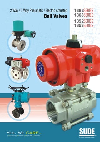
- 1. L M O F 2 Way / 3 Way Pneumatic / Electric Actuated 1362SERIES Ball Valves G 1363SERIES 1352SERIES H F 1353SERIES 7 K 8 W 4 M 7 L D I C J 8 X W 1 3 D 2 C 5 X 6 1 B 4 A 9 B A E Yes. We ARE.. . | Courteously | Attentively | Respectably | Effectively | SUDE An ISO 9001:2008 Certified Company R
- 2. 2 Way / 3 Way Electric / Pneumatic Actuated Ball Valves Index Introduction - Ball Valve Introduction ..............................................01 A ball valve, one type of quarter turn valve, is quite literally a ball placed in a passageway through which fluid flows. The ball has a hole through it, by Design features of which the valve opens and closes. When the ball is positioned so that the 3 way Ball valve ....................................... 02 hole runs the same direction as the passageway, the fluid simply flows through the hole, and the valve is open. However, when the ball is Dimension and Design positioned so that the hole is perpendicular to the passageway, the fluid as per ISO-5211 ....................................... 02 cannot pass through, and the valve is closed. The ball is controlled from Types Available ........................................ 03 outside the valve, often with Electric and Pneumatic actuator which will turned the Ball to 90 degrees, or a quarter turn, back and forth to open Specifications of Ball Valve ...................... 03 and close the valve. Refer typical cut section of the Ball valve. (Refer Figure 1). Exploded View of Ball Valve .................... 04 The basic ball valve, described above, is a two-way valve. This ball valve Pneumatic Actuator................................... 05 has a single, straight passageway bored through the ball, making two openings: one on each side, an inlet and an outlet. A ball valve can also Accessories .................................................. 06 be a three-way valve if a third hole is bored partially through the ball, until it meets the main hole, forming a T or L type. A three-way ball valve can ApplicationTests ........................................... 06 shut off one or all of the three passageways it connects. Because of the nature of the ball valve, it does not work well in situations Part List ........................................................ 07 in which fine control of the valve is needed. However, a ball valve works Electrical Actuator .................................... 08 very well for situations in which a flow needs to work on On/Off mode almost suitable for all medias. Ball valves also do not tend to develop Accessories .................................................. 09 problems if they are not used for long periods of time; they will still work perfectly when needed again. Control Panel Specification ........................... 09 There are three different types of ball valve. A full port ball valve offers no Typical Lined Valves ................................ 10 flow restriction, which means that when the ball valve is open, the liquid can flow freely through it. This is achieved by making the ball larger than GA Drawings the passage size, so that the hole bored through it can be the same size as the passage. A standard port ball valve does not have an oversized 1360 Series ........................................... 11-20 ball, and as a result the hole is one size smaller than the passageway. This presents a small amount of flow restriction as the fluid passes 1350 Series ........................................... 21-46 through the ball valve. A reduced port ball valve, on the other hand, has an even smaller ball and an even smaller hole, which creates significant flow restriction as the fluid passes through the valve. 01 1362/1363/1352/1353SERIES SUDE
- 3. Standardized center body mounting pad for actuators Full ANSI B16.34 Compliance Stainless Steel Name Plate to meet MSS SP25 Heavy-duty bolting and valve construction Automated Valve Manual Valve Figure-1 – Cut section of standard Ball valve Figure 2 - Stem seal arrangement of Ball valve Design features of 3 way Ball valve: SUDE Valve are of three-piece design available in both full and reduced port design and in a wide selection of body materials ? (stainless steel, carbon steel and alloys), and seats to meet a broad range of fluid types, pressures and temperatures. End connection available in BSP, NPT, Socket Weld, and Butt Weld or flanged. Socket weld and butt weld valves shall ? have fully-encapsulated body seal to facilitate inline welding without the need for disassembly. Weld-ends shall be “L” grade 316 stainless steel or carbon steel as required by the application. ? Stem seal shall be live-loaded using high-performance stainless steel disc springs (Belleville Washers). ? ? attachment shall be by integral mounting surface as part of the valve center section to eliminate the use of Actuator pressure-containing body bolts for actuator mounting. Refer Figure-2 which indicated the types of washers used for manual/automated valves. Dimension and Design as per ISO-5211. SUDE ? tagging shall be permanently affixed using spot welding, etching or riveting. Product ? stem shall be stainless steel. Ball and Valve shall provide modified equal-percentage flow characteristics when used in throttling control application, with ball ? having 'V'port design. Valve shall be designed, manufactured and tested to meet applicable industry standard. ? SUDE 1362/1363/1352/1353SERIES 02
- 4. Types Available SUDE 2 Way/3 Way Ball valves are available in General purpose & Fire Safe Design. Ball valves can be furnished with special seals to with stand vacuum of 10-3 torr, also with special treatment provision can be made for 10-6 torr application. Specifications Ball Valve Valve Size : 2 way Socket Weld, screwed & Flanged ends (Size ½” to 10”) and 3 way Mixing or Diverting design are available with a Size ½” to 2” standard in screwed and flanged up to 200mm). These valves can be made available with Double Acting, Spring return type Pneumatic actuators and Single/Three Phase Electric Actuators. (Typical exploded view of Ball valve, refer Figure 3) Port Size : Refer Dimensional assembly drawing Tabular column End Connection : Screwed / Flanged / Socket Weld. Type of Construction : Single Piece / 2 Piece / 3 Piece Reduce Bore / Full Bore design. Body Material : Carbon steel / S.S.316 / S.S.304 / PVC / PP / PE / Teflon. Ball Material : S.S.316 / S.S.304 / PVC / PP / PE / Teflon. Seating Material : Teflon / Acetyl Resin / Any other. Action of Valve : Normally opened / normally closed / 3 way Diverting or Mixing in case of 3 way Valves. Characteristic : On, Off / Modified Control Up to 60 Degree opening. 03 1362/1363/1352/1353SERIES SUDE
- 5. Exploded View of Ball Valve SUDE 9 25 8 7 11 12 2 15 6 14 17 5 5 3 6 1 2 16 4 10 Figure 3 – Exploded view of Ball valve Sr. No. Parts Material 1 Body C.S., 316 S.S., Brass 2 Pipe End C.S., 316 S.S., (316L for weld ends) 3 Ball 316 S.S., Chrome-Plated Brass 4 Stem 316 S.S., Brass 5 Seat TFE, Reinforced TFE, Buna, Neoprene, Polyfill, UHMWPE, High-per Fill, Delrin 6 Body Seal Buna, Viton, EPR, TFE, Neoprene, TFE Coated 316 S.S. "S" Gaskets, Graphite Coated 316 S.S. "S" Gasket. UHMWPE Graphite (2" only) 7 Stem Seal Follower 316 S.S. 8 Stop Pin (1" and up) ¼"- 1½" S.S. or C.S.Zinc-Plated; Stop Pin (¼"-¾") 2"-4" C.S., Black Oxide-Coated 9 Body Bolts ¼"-2" C.S.:ASTM A193 GR-B7 S.S.: ASTM A193 GR-B8 3"-4" C.S.:Clack Oxide-Coated 10 Body Nuts ¼"-2" C.S.:ASTM A194 GR-2H S.S.: ASTM A194 GR-B8 3"-4" C.S.:Black Oxide-Coated 11 Lock washer Carbon Steel: Zinc-Plated or S.S. 12 Seal Protector PEEK 13 Nameplate (not shown) 304 Stainless Steel 14 Stem Seal Size 2", 3", 4" Valves Glass-filled TFE 15 Centering Washer C.S.; 316 S.S. (3" & 4" only) 16 Thrust Bearing Glass-filled TFE 17 Seat Retainer Carbon Steel or 316 S.S. 18 Retaining Nut Carbon Steel: Zinc-Plated or S.S. SUDE 1362/1363/1352/1353SERIES 04
- 6. Pneumatic Actuator SUDE Pressure Temperature Rating Assembled with : 58 22 32 122 212 302 392 482 Pneumatic Rotary Double Acting Stay put type ? 50 Actuator OR VIR 40 REN GIN ? Return Actuator available for Fail safe Spring FOR PTE operation. CED E SE 30 Pneumatic actuators are available in rotary construction in PTE AT R ES Double and spring return in on/off and modulating duty ING EAT (R) 20 RIN G (R format. Actuators will be inherently failed safe but fail position (open or closed) should be noted. Pneumatic ) 10 actuators are supplied with Electro pneumatic positioners which work on continuous pressurized air of 60 psi and 0 input signal of 4 to 20mA with feed back 4 to 20mA For 50 0 50 100 150 200 250 details refer Actuator catalogue. Actuator Construction SUDE The piston incorporates racks and end covers are die Air Pressure Requirement : casted in aluminum alloy. Barrel is extruded aluminium a) For Double Acting Actuator - 3.5 kg / cm2 alloy hardened and treated, further finished with deep (Minimum) & 8.5 kg / cm2 (Maximum) anodized process to form a protective layer to resist b) For Spring Return Actuator - 4.0 kg / cm2 atmospheric corrosion. The actuators are also available (Minimum) & 8.5 kg / cm2 (Maximum) in stainless steel 316 & Nylon plastic construction for However Air Pressure Requirement is much dependent food grade and chemical industries application. The on size of the valve, working pressure, quality of Ball Valve internal materials of the aluminum, SS 316 & Nylon and many other factors. plastic actuator are having pinion which is made up of steel, precision cut, heat treated and ground & also has a For Double Acting Actuator: high trade of synthetic seals. The actuators before 4 way 5 port single Coil / Double Coil solenoid valve in assembly is lubricated with high temperature resistant general purpose or Flame proof and explosion coils construction. smooth grease. The actuators are with compact design operates through 90 degree angle of actuation. The For Spring Return Actuator: Actuator is also available in 180 degree rotation. The 3 way Single Coil / Double Coil solenoid valve in General exploded view of Actuator Refer Figure 4. purpose or Flame proof and explosion Coils construction. 05 1362/1363/1352/1353SERIES SUDE
- 7. Accessories SUDE Accessory Common for Double Acting / Spring Return Actuator : a) Pressure Regulator b) Limit Switches c) Filter Regulator with Lubricator d) Gear Box with hand wheel for manual operation e) Valve Positioner for characteristic controlled application. f) I to P Converter. g) Electro pneumatic positioners h) Position Indicator i) Position Transmitter j) Cyclic Timer OR Sequential Timer k) 3 Way / 4 Way Key operated valves l) Stimulator m) Travel Stops n) Flow Restricter o) Silencers with Flow Control Valve Optional : a) PID Controller along with PT - 100 Senso supplied with panel. b) Pressure Transmitter supplied with panel. Application SUDE For control of Air, water, oil, gas, steam, power generation, atomic energy pulp & paper, chemical, petrochemicals, printing, plastic processing, food & beverages, wood industries, tea & coffee plant and others. Tests SUDE The valves are tested according to their respective standards for hydrostatic, seat leakage and working pressure tests. Unless and otherwise specified Ball valves are Constructed and tested for 10 kg/cm2 working pressure with modified construction they can be made to suit a pressure of 300 bar. Notes : a) Actuator rating is for valve working pressure 10 kg / cm2 b) Timing given is approximate and is useful as an indicating figure only when solenoid valve is directly coupled with the Actuator. Average time under 50% load condition is 80 PSI working pressure. c) All data is complied in laboratory test, in actual field, working may differ. d) Width and weight will change with rating of flanges and accessories. SUDE 1362/1363/1352/1353SERIES 06
- 8. Part List - Pneumatic Actuator SUDE 9 7 8 6 5 4 12 3 2 1 13 10 15 14 11 13 Figure – 4 – Exploded View of Pneumatic Actuator No. Description Quantity Material 1 Allen Screw / Spring Clip 12 / 2 AISI -304 Stainless Steel 2 Double Acting Cap 2 Aluminium Alloy (2) + (1) 3 Cap O-ring 2 N.B.R. 4 Piston 2 Aluminium Alloy 5 Cylinder / Body 1 Aluminium Alloy (2) + (1) 6 Washer 1 Polyamide 6 7 Spring Clip 1 Steel (3) 8 Position Indicator 1 Polymide 9 Guide Ring 4 P.T.F.E. + Bronze 10 O-Ring 2 N.B.R. 11 O-Ring 4 N.B.R. 12 Single Acting Cap 2 N.B.R. 13 Springs Set 2 DIN - 17223-C (2) (4) 14 Shaft 1 Steel (2) 15 Gear 1 Aluminium Alloy (5) 07 1362/1363/1352/1353SERIES SUDE
- 9. Electrical Actuator - Construction SUDE Single Phase Single phase SDTORK Actuator is provided with Stall duty motor used for quarter turn application. Actuator is suitable for inching operation too and they can be supplied with extra limit switches for remote position indication. The Actuator are available in general purpose, Dust proof & Flame proof & Explosion proof housing approved by CMRS Dhanbad. Three phases SDTORK Actuator is basically a worm gear type reduction gear box. A single stage grease bath worm gear gives quietness and reliability in operation. The valve can be fully opened, fully closed or adjusted to any intermediate position. The rectory force on the worm shaft which is a 'Floating one' is directly proportional to the out put torque and is absorbed by a set of disc springs. The lateral movement of the worm shaft under load, trips closes the Torque switch. The driving motor is a TEFC/TESC squirrel cage class F IP 65 enclosure motor combining low inertia with a high starting and stalling torque. Three Phase Three phase Actuator are fitted with torque limit switches & travel limit switches & also they are in built with manual hand wheel used for operating the actuator manually in case of power failure. Actuator is also supplied with various shaft designs to suit rising & non rising stem valve. Three phases are also provided with space heater. This actuator is also available in slow mode operation which is used for multi turn application. Assembled with : ? phase 230V AC Actuator Alternatively 24V AC & 110V AC OR Single ?phase 415V AC Actuator Three Easier interface with digital control devices. Electrical actuators must have a voltage selection, typical actuators voltages are 24V AC, 110V AC, 240V AC and 415V AC. Fail safe electric actuators are also called spring return and the fail positioning (open or closed) should be noted. For detail on the Electric actuator refer Sdtork pune and asked for detailed literature. The spring return Electrical actuators are available for low torque, for higher values we suggest you to use reversible stay put type actuator. SUDE 1362/1363/1352/1353SERIES 08
- 10. Accessories For Actuator SUDE a) Travel Limit Switches - 2 nos Actuator can also be supplied with : b) Auxiliary Limit Switches - 2 nos Single Phase OR Three phase Panel for switching the valve On / Off through Push Buttons for local operation under manual mode OR through PLC under Auto c) Hand wheel for Manual operation mode through 4-20 mA, 0 to 10V DC. d) Local position indicator e) Potentiometer for feed back Common Accessory for Single Phase / Three Phase Actuator : f) Torque limit switches a) Honeywell / any other make PID Controller along with PT 100 sensor with g) Position Transmitter built in panel as an option. b) Honeywell / any other make pressure Transmitter where based on setting pressure valve will open & close through PID with built in panel as a option. c) Sequential timer 0 to 30 channel for sequence operation. The Actuators can be supplied with a panel having d) Cyclic timer having On time 1 to 60 seconds & Off time 1 to 60 min for Auto Calibration facility. sequencing operation. Control Panel Specification : SUDE a) Input : Single Phase 230V AC OR 3 Phase 415V AC, 4 wire supply. b) Output supply: Single Phase 230V AC OR 3 phase 415V AC Reversible supply. c) Auto / Manual selection : Selector switch provided. In Auto mode open & close operation is controlled by 4-20mA Input & under Manual mode operation is through Push buttons. d) Indications : Zero to a100% valve position display, R, Y, B Phase Wall mounted control panel. Indication [applicable only for 3 phase] Open & Close, Fully open & Fully close indication. e) Main switch - Single Phase OR 3 Phase MCB for mains On / Off. f) Phase fail / error protection provided. g) Fuse protection provided for each phase. h) Protection from over torque - If Actuator gets over torque the torque switch trips & the system protects the motor. Also provided with 10 metes cable for Motor & Feed back with connectors. Notes : ?Actuator rating is for valve working pressure 10 kg / cm². ? given is approximate and is useful as an indicating figure. Timing ? is complied in laboratory test, in actual field, working may differ. All data Integral Starter ? and weight will change with rating of flanges and accessories. Width 09 1362/1363/1352/1353SERIES SUDE
- 11. Typical Lined Valves which can be Automated when Assembled with Actuators. SUDE A) TEFLON LINED TWO PIECE BALL VALVE 8 7 5 SL.NO. PART NAME MATERIAL 4 1 Center Piece ASTM A 216 GR WCB 6 2 Side Piece ASTM A 216 GR WCB 3 Ball TEFLON WITH METAL CORE (ALUMINIUM, SS) 3 4 Steam TEFLON LINED C. STEEL 10 5 Gland S.S. 1 6 Seat Ring PTFE/TEFLON 7 Gland Packing PTFE/TEFLON 2 8 Gland Washer S.S. 9 9 Stud & Nuts S.S. Figure 5 – Two Pieces Lined Ball Valves 10 Lining Material TEFLON B) PFA or FEP or PVDF LINED BALL VALVE IN 3 PIECE DESIGN 8 9 7 5 SL.NO. PART NAME MATERIAL 4 1 Center Piece ASTM A 216 GR WCB 2 Side Piece ASTM A 216 GR WCB 2 3 Ball TEFLON WITH METAL CORE (ALUMINIUM, SS) 11 4 Steam TEFLON LINED C. STEEL 5 Gland S.S. 3 6 Seat Ring PTFE/TEFLON 7 Gland Packing PTFE/TEFLON 1 8 Gland Washer S.S. 6 9 Cap & Handle M.S. or S.S. 10 10 Stud & Nuts S.S. Figure 6 – Three Piece Lined Ball valves 11 Lining Material PFA or FEP or PVDF C) HIGH PRESSURE BALL VALVE Specifications Screwend but weld socket weld pipe end VALVE SIZES ¼", 3/8", 1/2", 3/4", 1", 1¼", 1½", 2" Standardized center body mounting pad for From 20 micron absolute to: actuators ¼"-¾"-3000 psi VALVE PRESSURE RATINGS 1"-2500 psi Complete Inter- changeability at body 1¼"-2"-2000 psi & Pipe End options. BODY AND PIPE END MATERIALS Carbon Steel, Stainless Steel Stainless Steel, Monel, Alloy 20, BALL/STEM Hastelloy C Choice of Carbon Steel or 316 Lubetal Delrin-Maximum temp. 1800F. Stainless Steel Fully Enclosed Body Taping Body & Pipe End. SEALS Lubetal will handle the full range of pressure within the valves rating THRUST BEARING Delrin STEM SEALS Polyfill and PEEK BODY SEALS Buna, Viton, EPR, Neoprene Figure 7 – Cut section of High Pressure Ball valve VALVE TEMPERATURE RANGE -200F to 1800F SUDE 1362/1363/1352/1353SERIES 10
- 12. 2-way Pneumaticaly Operated Full Bore Screwed Ball Valve 1362 M E H D ØG F 10 I Q J K W 5 7 C 6 P 4 X 3 B 2 1 SOCKET-WELD END A L M E H D ØG F 10 I J 9 5 K 7 8 6 4 3 2 1 A PART LIST S.No. BODY CARBON STEEL STAINLESS STEEL 1 BODY ASTM A216 Gr. WCB ASTM A351 Gr. CF8M 2 BODY CONNECTOR ASTM A216 Gr. WCB ASTM A351 Gr. CF8M 3 BALL ASTM A351 Gr.CFSM ASTM A351 Gr.CFSM 4 SEAT PTFE PTFE 5 STEM AISI 316 AISI 316 6 BODY SEAL GRAPHITE GRAPHITE 7 GLAND PACKING GRAPHITE GRAPHITE 8 STEM SEAL 25% CARBON-FILLED PTFE 25% CARBON-FILLED PTFE 9 COUPLER EN8 SS 10 PNEUMATIC ACTUATOR ALUMINIUM ALUMINIUM WT. OF OPERATING AIR CONSUMP- VALVE TIME TION IN LTR SIZE MODEL NUMBER A B C D E F G H I J K L M P Q W X ASSY Cv OPEN CLOSE TO TO IN KGS. (SEC.) (SEC.) OPEN CLOSE 1362/15/BSP/FB/DAW 73 22.2 9.7 8 7.5 20 9 68.5 85 31 37.5 - 109 27 252 50 15 1.5 12 0.1 0.1 0.075 0.05 15 1362/15/BSP/FB/SAW 73 22.2 9.7 8 7.5 20 9 68.5 85 31 37.5 143.5 109 27 252 50 15 1.6 12 0.15 0.15 0.075 - 1362/20/BSP/FB/DAW 95 27.6 12.7 8 7.5 20 9 68.5 85 31 37.5 - 109 28.8 253.8 50 20 1.75 32 0.1 0.1 0.075 0.05 20 1362/20/BSP/FB/SA00 95 27.6 12.7 10 11 30 13.8 80 110 45 44 160 125 28.8 253.8 50 20 1.9 32 0.2 0.2 0.15 - 1362/25/BSP/FB/DA00 116 34.3 12.7 10 11 30 13.8 80 110 45 44 - 125 35.4 260.4 70 25 5 46 0.15 0.15 0.15 0.1 25 1362/25/BSP/FB/SA05 116 34.3 12.7 10 11 30 13.8 98 122 47 53 194 146 35.4 260.4 70 25 5.5 46 0.25 0.25 0.28 - 1362/40/BSP/FB/DA00 128 49.2 13.8 10 11 30 13.8 80 110 45 44 - 125 45 290 70 40 5 120 0.15 0.15 0.15 0.1 40 1362/40/BSP/FB/SA05 128 49.2 13.8 10 11 30 13.8 98 122 47 53 194 146 45 290 70 40 5.5 120 0.25 0.25 0.28 - 50 1362/50/BSP/FB/DA05 128 49.2 13.8 10 11 30 13.8 98 122 47 53 - 182 45 290 70 50 6 120 0.2 0.2 0.28 0.25 11 1362/1363/1352/1353SERIES SUDE
- 13. 2-way Pneumaticaly Operated Reduced Bore Screwed Ball Valve 1362 M E H D ØG F I Q J K C W 5 7 B 6 P 4 X 3 2 SOCKET-WELD END 1 A L M H E D ØG F 10 I J 9 5 K 7 8 6 4 3 2 1 A PART LIST S.No. BODY CARBON STEEL STAINLESS STEEL 1 BODY ASTM A216 Gr. WCB ASTM A351 Gr. CF8M 2 BODY CONNECTOR ASTM A216 Gr. WCB ASTM A351 Gr. CF8M 3 BALL ASTM A351 Gr.CFSM ASTM A351 Gr.CFSM 4 SEAT PTFE PTFE 5 STEM AISI 316 AISI 316 6 BODY SEAL GRAPHITE GRAPHITE 7 GLAND PACKING GRAPHITE GRAPHITE 8 STEM SEAL 25% CARBON-FILLED PTFE 25% CARBON-FILLED PTFE 9 COUPLER EN8 SS 10 PNEUMATIC ACTUATOR ALUMINIUM ALUMINIUM WT. OF OPERATING AIR CONSUMP- VALVE TIME TION IN LTR SIZE MODEL NUMBER A B C D E F G H I J K L M P Q W X ASSY Cv OPEN CLOSE TO TO IN KGS. (SEC.) (SEC.) OPEN CLOSE 1362/15/BSP/RB/DAW 67 22.2 9.7 8 7.5 20 9 68.5 85 31 37.5 - 109 27 162 50 15 1.5 8 0.1 0.1 0.075 0.05 15 1362/15/BSP/RB/SAW 67 22.2 9.7 8 7.5 20 9 68.5 85 31 37.5 143.5 109 27 162 50 15 1.6 8 0.15 0.15 0.075 - 1362/20/BSP/RB/DAW 73 27.6 12.7 8 7.5 20 9 68.5 85 31 37.5 - 109 28.8 163.8 50 20 1.75 12 0.1 0.1 0.075 0.05 20 1362/20/BSP/RB/SAW 73 27.6 12.7 8 7.5 20 9 68.5 85 31 37.5 143.5 109 28.8 163.8 50 20 1.9 12 0.15 0.15 0.075 - 1362/25/BSP/RB/DAW 95 34.3 12.7 8 7.5 20 9 68.5 85 31 37.5 - 109 35.4 170.4 50 25 2.5 32 0.1 0.1 0.075 0.05 25 1362/25/BSP/RB/SA00 95 34.3 12.7 10 11 30 13.8 80 110 45 44 160 125 35.4 170.4 50 25 2.7 32 0.2 0.2 0.15 - 1362/32/BSP/RB/DA00 107 43.1 12.7 10 11 30 13.8 80 110 45 44 - 125 38 218 70 32 4.2 46 0.15 0.15 0.15 0.1 32 1362/32/BSP/RB/SA05 107 43.1 12.7 10 11 30 13.8 98 122 47 53 194 146 38 230 70 32 4.7 46 0.25 0.25 0.28 - 1362/40/BSP/RB/DA00 116 49.2 12.7 10 11 30 13.8 80 110 45 44 - 125 45 225 70 40 5 82 0.15 0.15 0.15 0.1 40 1362/40/BSP/RB/SA05 116 49.2 12.7 10 11 30 13.8 98 122 47 53 194 146 45 237 70 40 5.5 82 0.25 0.25 0.28 - 1362/50/BSP/RB/DA00 128 61.7 15.9 10 11 30 13.8 80 110 45 44 - 125 48 228 70 50 6 120 0.15 0.15 0.15 0.1 50 1362/50/BSP/RB/SA05 128 61.7 15.9 10 11 30 13.8 98 122 47 53 194 146 48 240 70 50 7 120 0.25 0.25 0.28 - 1362/50/BSP/RB/DA05 128 61.7 15.9 10 11 30 13.8 98 122 47 53 - 146 48 240 70 50 7 120 0.2 0.2 0.28 0.25 SUDE 1362/1363/1352/1353SERIES 12
- 14. 2-way Pneumaticaly Operated Full Bore Ball Valve Class 150 1362 O J G ØI F H 11 K L P M 6 W 7 4 5 2 X 3 D C 1 8 B G A O J G F H 11 K L 10 M W 6 12 7 4 5 2 9 X 3 D C 1 8 B G A PART LIST S.No. BODY CARBON STEEL STAINLESS STEEL 1 BODY ASTM A216 Gr. WCB ASTM A351 Gr. CF8M 2 BALL ASTM A351 Gr.CFSM ASTM A351 Gr.CFSM 3 SEAT PTFE PTFE 4 STEM AISI 316 AISI 316 5 BODY SEAL GRAPHITE GRAPHITE 6 GLAND PACKING GRAPHITE GRAPHITE 7 STEM SEAL 25% CARBON-FILLED PTFE 25% CARBON-FILLED PTFE 8 INSERT ASTM A 105/ASTM A216 GR. AISI 316 OR ASTM A351 WCB/IS 1875 C12 Gr. CF 8M 9 INSERT GASKET GRAPHITE GRAPHITE 10 COUPLER EN8 SS 11 PNEUMATIC ACTUATOR ALUMINIUM ALUMINIUM 12 BRACKET IS 2062 IS 2062 WT. OF OPERATING AIR CONSUMP- VALVE TIME TION IN LTR SIZE MODEL NUMBER A B C D F G H I J K L M N O P W X ASSY Cv OPEN CLOSE TO TO IN KGS. (SEC.) (SEC.) OPEN CLOSE 1362/15/FL150/FB/DAW 108 46 12.7 89 8 7.5 20 9 68.5 85 31 37.5 - 109 179.5 50 14 2.75 12 0.1 0.1 0.075 0.05 15 1362/15/FL150/FB/SAW 108 46 12.7 89 8 7.5 20 9 68.5 85 31 37.5 143.5 109 179.5 50 14 2.9 12 0.15 0.15 0.075 - 1362/20/FL150/FB/DAW 117 50 19.1 98 8 7.5 20 9 68.5 85 31 37.5 - 109 184 50 20 4 32 0.1 0.1 0.075 0.05 20 1362/20/FL150/FB/SA00 117 50 19.1 98 10 11 30 13.8 80 110 45 44 160 125 209 50 20 4.25 32 0.2 0.2 0.15 - 1362/25/FL150/FB/DA00 127 56 25.4 108 10 11 30 13.8 80 110 45 44 - 125 214 50 25 4.9 46 0.15 0.15 0.15 0.1 25 1362/25/FL150/FB/SA05 127 56 25.4 108 10 11 30 13.8 98 122 47 53 194 146 226 50 25 6.2 46 0.25 0.25 0.28 - 1362/40/FL150/FB/DA05 165 75 38.1 127 10 11 30 13.8 98 122 47 53 - 146 255.5 70 38 10.7 120 0.2 0.2 0.28 0.25 40 1362/40/FL150/FB/SA05 165 75 38.1 127 10 11 30 13.8 98 122 47 53 194 146 255.5 70 38 11.5 120 0.25 0.25 0.28 - 1362/50/FL150/FB/DA10 178 84 50.8 152 10 11 30 13.8 102 127 50.5 55 - 182 273 70 51 14.7 240 0.25 0.25 0.35 0.32 50 1362/50/FL150/FB/SA10 178 84 50.8 152 10 11 30 13.8 102 127 50.5 55 236 182 273 70 51 15.5 240 0.3 0.3 0.35 - 1362/65/FL150/FB/DA20 191 77 64.1 178 16 11 30 21.8 127 161 71 67 - 234 330 80 64 21.4 325 0.4 0.4 0.8 0.7 65 1362/65/FL150/FB/SA20 191 77 64.1 178 16 11 30 21.8 127 161 71 67 312 234 330 80 64 22 325 0.5 0.5 0.8 - 1362/80/FL150/FB/DA25 203 99 76.2 191 16 11 30 21.8 152 191 86 78 - 276 366.5 80 76 28 600 0.5 0.5 1.5 1.2 80 1362/80/FL150/FB/SA25 203 99 76.2 191 16 11 30 21.8 152 191 86 78 362 276 366.5 80 76 30.3 600 0.8 0.8 1.5 - 1362/100/FL150/FB/DA30 229 108 101.6 229 16 11 30 21.8 177 211 96 94 - 349 405.5 80 102 50.5 830 0.6 0.6 2.05 1.9 100 1362/100/FL150/FB/SA40 229 108 101.6 229 32 20 50 41.9 226 212 116 120 598 444 405.5 80 102 54 830 2.4 1.2 2.05 - 1362/150/FL150/FB/DA40 394 179 150.8 279 32 20 50 41.9 226 212 116 120 - 444 452.5 100 152 101.5 2100 1.2 1.2 5.3 5.3 150 1362/150/FL150/FB/SA50 394 179 150.8 279 32 20 50 41.9 258 313 133 135 694 524 552.5 100 152 109 2100 6 6 10.5 - 1362/200/FL150/FB/DA50 457 206 203 - 32 20 50 41.9 258 313 133 135 - 524 - 100 203 192 3000 2 2 10.5 7 200 1362/200/FL150/FB/SA70 457 206 203 - 43.5 50 - 43.5 403 428 191 216 742.5 - - 100 203 210 3000 15 10 31 - 13 1362/1363/1352/1353SERIES SUDE
- 15. 2-way Pneumaticaly Operated Full Bore Ball Valve Class 300 1362 O J G ØI F H 11 K L P M 6 W 7 4 5 2 X 3 D C 1 8 B G A O J G F H 11 K L 10 M W 6 12 7 4 5 2 9 X 3 D C 1 8 B G A PART LIST S.No. BODY CARBON STEEL STAINLESS STEEL 1 BODY ASTM A216 Gr. WCB ASTM A351 Gr. CF8M 2 BALL ASTM A351 Gr.CFSM ASTM A351 Gr.CFSM 3 SEAT PTFE PTFE 4 STEM AISI 316 AISI 316 5 BODY SEAL GRAPHITE GRAPHITE 6 GLAND PACKING GRAPHITE GRAPHITE 7 STEM SEAL 25% CARBON-FILLED PTFE 25% CARBON-FILLED PTFE 8 INSERT ASTM A 105/ASTM A216 GR. AISI 316 OR ASTM A351 WCB/IS 1875 C12 Gr. CF 8M 9 INSERT GASKET GRAPHITE GRAPHITE 10 COUPLER EN8 SS 11 PNEUMATIC ACTUATOR ALUMINIUM ALUMINIUM 12 BRACKET IS 2062 IS 2062 WT. OF OPERATING AIR CONSUMP- VALVE TIME TION IN LTR SIZE MODEL NUMBER A B C D F G H I J K L M N O P W X ASSY Cv OPEN CLOSE TO TO IN KGS. (SEC.) (SEC.) OPEN CLOSE 1362/15/FL300/FB/DAW 140 78 12.7 95 8 7.5 20 9 68.5 85 31 37.5 - 109 182.5 50 15 3.5 12 0.1 0.1 0.075 0.05 15 1362/15/FL300/FB/SAW 140 78 12.7 95 8 7.5 20 9 68.5 85 31 37.5 143.5 109 182.5 50 15 3.6 12 0.15 0.15 0.075 - 1362/20/FL300/FB/DA00 153 85 19.1 117 10 11 30 13.8 80 110 45 44 - 125 218.5 50 20 4.3 32 0.15 0.15 0.15 0.1 20 1362/20/FL300/FB/SA00 153 85 19.1 117 10 11 30 13.8 80 110 45 44 160 125 218.5 50 20 5.6 32 0.2 0.2 0.15 - 1362/25/FL300/FB/DA05 165 94 25.4 124 10 11 30 13.8 98 122 47 53 - 146 234 50 25 6.8 46 0.2 0.2 0.28 0.25 25 1362/25/FL300/FB/SA05 165 94 25.4 124 10 11 30 13.8 98 122 47 53 194 146 234 50 25 7 46 0.25 0.25 0.28 - 1362/40/FL300/FB/DA05 191 100 38.1 156 10 11 30 13.8 98 122 47 53 - 146 270 70 38 11.7 120 0.2 0.2 0.28 0.25 40 1362/40/FL300/FB/SA10 191 100 38.1 156 10 11 30 13.8 102 127 50.5 55 236 182 275 70 38 12.5 120 0.3 0.3 0.35 - 1362/50/FL300/FB/DA10 216 84 50.8 165 10 11 30 13.8 102 127 50.5 55 - 182 279.5 70 51 17.7 240 0.25 0.25 0.35 0.32 50 1362/50/FL300/FB/SA15 216 84 50.8 165 10 11 30 13.8 115 148 63 60 266 203 300.5 70 51 18.5 240 0.4 0.4 0.65 - 1362/65/FL300/FB/DA20 241 83 64.1 191 16 11 30 21.8 127 161 71 67 - 234 336.5 80 64 29.4 325 0.4 0.4 0.8 0.7 65 1362/65/FL300/FB/SA20 241 83 64.1 191 16 11 30 21.8 127 161 71 67 312 234 336.5 80 64 30 325 0.5 0.5 0.8 - 1362/80/FL300/FB/DA30 283 99 76.2 210 16 11 30 21.8 177 211 96 94 - 349 396 80 76 37.7 600 0.6 0.6 2.05 1.9 80 1362/80/FL300/FB/SA30 283 99 76.2 210 16 11 30 21.8 177 211 96 94 479 349 396 80 76 40 600 1.2 1.2 2.05 - 1362/100/FL300/FB/DA40 305 122 101.6 254 32 20 50 41.9 226 212 116 120 - 444 419 80 102 67 830 1.2 1.2 5.3 5.3 100 1362/100/FL300/FB/SA50 305 122 101.6 254 32 20 50 41.9 258 313 133 257.5 694 524 520 80 102 70 830 6 6 10.5 - 1362/150/FL300/FB/DA50 403 179 150.8 318 32 20 50 41.9 258 313 133 257.5 - 524 572 100 152 133 2100 2 2 10.5 7 150 1362/150/FL300/FB/SA70 403 179 150.8 318 43.5 50 50 43.5 403 428 191 216 742.5 - 687 100 152 140 2100 15 10 31 - 1362/200/FL300/FB/DA50 502 231 203 - 32 20 50 41.9 258 313 133 257.5 - 524 - 100 203 223 3000 2 2 10.5 7 200 1362/200/FL300/FB/SA70 502 231 203 - 43.5 50 50 43.5 403 428 191 216 742.5 - - 100 203 230 3000 15 10 31 - SUDE 1362/1363/1352/1353SERIES 14
- 16. 2-way Pneumaticaly Operated Reduced Bore Ball Valve Class 150 1362 O G J F ØI H 12 P K L 11 M W 8 7 5 6 D C X 9 1 3 4 1.6 E B A N O G J F H 12 K L 11 10 M 8 7 5 6 D C X 2 9 1 3 4 1.6 E B A PART LIST S.No. BODY CARBON STEEL STAINLESS STEEL 1 BODY ASTM A216 Gr. WCB ASTM A351 Gr. CF8M 2 INSERT ASTM A1 05 OR ASTM A21 6 Gr. WCB ASTM A316 OR ASTM A351 Gr.WCB 3 BALL ASTM A315 Gr.CF8M ASTM A315 Gr.CF8M 4 SEAT PTFE PTFE 5 STEM AISI 316 AISI 316 6 BODY SEAL PTFE PTFE 7 GLAND PACKING GRAPHITE GRAPHITE 8 STEM SEAL 35% CARBON-FILLED PTFE 35% CARBON-FILLED PTFE 9 INSERT SEAL 15mm-40mm, 200mm: METAL-TO-METAL 15mm-40mm, 200mm: METAL-TO- 50mm-150mm: GRAPHITE METAL, 50mm-150mm: GRAPHITE 10 COUPLER EN8 EN8 11 BRACKET IS 2062 IS 2062 12 PNEUMATIC ACTUATOR ALUMINIUM ALUMINIUM WT. OF OPERATING AIR CONSUMP- VALVE TIME TION IN LTR SIZE MODEL NUMBER A B C D E F G H I J K L M N O P W X ASSY Cv OPEN CLOSE TO TO IN KGS. (SEC.) (SEC.) OPEN CLOSE 1362/15/FL150/RB/DAW 108 62 12.7 89 11.5 8 7.5 20 9 68.5 85 31 37.5 - 109 135 50 12 2.5 8 0.1 0.1 0.075 0.05 15 1362/15/FL150/RB/SAW 108 62 12.7 89 11.5 8 7.5 20 9 68.5 85 31 37.5 143.5 109 135 50 12 2.6 8 0.15 0.15 0.075 - 1362/20/FL150/RB/DAW 117 68 19.1 99 11.5 8 7.5 20 9 68.5 85 31 37.5 - 109 184.5 50 15 3 12 0.1 0.1 0.075 0.05 20 1362/20/FL150/RB/SAW 117 68 19.1 99 11.5 8 7.5 20 9 68.5 85 31 37.5 143.5 109 184.5 50 15 3.2 12 0.15 0.15 0.075 - 1362/25/FL150/RB/DAW 127 70 25.4 108 11.5 8 7.5 20 9 68.5 85 31 37.5 - 125 209 70 32 6.75 32 0.1 0.1 0.075 0.05 25 1362/25/FL150/RB/SA00 127 70 25.4 108 11.5 10 11 30 13.8 80 110 45 44 160 125 234 70 32 7 32 0.2 0.2 0.15 - 1362/40/FL150/RB/DA00 165 70 38.1 127 14.5 10 11 30 13.8 80 110 45 44 - 125 243.5 70 32 6.75 46 0.15 0.15 0.15 0.1 40 1362/40/FL150/RB/SA05 165 70 38.1 127 14.5 10 11 30 13.8 98 122 47 53 194 146 255.5 70 32 7 46 0.25 0.25 0.28 - 1362/50/FL150/RB/DA00 178 107 50.8 152 16 10 11 30 13.8 80 110 45 44 - 125 256 70 38 10 120 0.15 0.15 0.15 0.1 50 1362/50/FL150/RB/SA05 178 107 50.8 152 16 10 11 30 13.8 98 122 47 53 194 146 268 70 38 10.5 120 0.25 0.25 0.28 - 1362/50/FL150/RB/DA05 178 107 50.8 152 16 10 11 30 13.8 98 122 47 53 - 146 268 70 38 11.5 120 0.2 0.2 0.28 0.25 1362/80/FL150/RB/DA20 203 120 76.2 191 19.5 16 11 30 21.8 127 161 71 67 - 234 336.5 80 64 22 325 0.4 0.4 0.8 0.7 80 1362/80/FL150/RB/SA20 203 120 76.2 191 19.5 16 11 30 21.8 127 161 71 67 312 234 336.5 80 64 24.2 325 0.5 0.5 0.8 - 1362/100/FL150/RB/DA25 229 130 102 229 24 16 11 30 21.8 152 191 86 78 - 276 385.5 80 76 36.2 600 0.5 0.5 1.5 1.2 100 1362/100/FL150/RB/SA25 229 130 102 229 24 16 11 30 21.8 152 191 86 78 362 276 385.5 80 76 39.5 600 0.8 0.8 1.5 - 1362/150/FL150/RB/DA30 267 138 151 280 25.4 16 11 30 21.8 177 211 96 94 - 349 451 100 102 59 830 0.6 0.6 2.05 1.9 150 1362/150/FL150/RB/SA40 267 138 151 280 25.4 32 20 50 41.9 226 212 116 120 598 444 451 100 102 86.5 830 2 2 5.3 - 1362/200/FL150/RB/DA40 292 148 203 343 28.4 32 20 50 41.9 226 212 116 120 - 444 483.5 100 152 136 2100 1.2 1.2 5.3 5.3 200 1362/200/FL150/RB/SA50 292 148 203 343 28.4 32 20 50 41.9 258 313 133 135 694 524 584.5 100 152 177 2100 6 6 10.5 - 1362/250/FL150/RB/DA50 330 165 254 406 30.5 32 20 50 41.9 258 313 133 135 - 524 641 125 203 245 3000 2 2 10.5 7 250 1362/250/FL150/RB/SA70 330 165 254 406 30.5 43.5 50 - 43.5 403 428 191 216 742.5 - 756 125 203 292 3000 15 10 31 - 15 1362/1363/1352/1353SERIES SUDE
- 17. 2-way Pneumaticaly Operated Reduced Bore Ball Valve Class 300 1362 O G J F H 11 K L P 9 10 5 w 7 8 1 4 X C D 3 2 E 1.6 6 B A N O J F G H 11 K L 9 5 w 10 7 8 1 4 X C D 3 2 E 1.6 6 B A PART LIST S.No. BODY CARBON STEEL STAINLESS STEEL 1 BODY ASTM A216 Gr. WCB ASTM A351 Gr. CF8M 2 INSERT ASTM A1 05 OR ASTM A21 6 Gr. WCB ASTM A316 OR ASTM A351 Gr.WCB 3 BALL ASTM A315 Gr.CF8M ASTM A315 Gr.CF8M 4 SEAT PTFE PTFE 5 STEM AISI 316 AISI 316 6 BODY SEAL PTFE PTFE 7 GLAND PACKING GRAPHITE GRAPHITE 8 STEM SEAL 35% CARBON-FILLED PTFE 35% CARBON-FILLED PTFE 9 COUPLER EN8 EN8 10 BRACKET IS 2062 IS 2062 11 PNEUMATIC ACTUATOR ALUMINIUM ALUMINIUM WT. OF OPERATING AIR CONSUMP- VALVE TIME TION IN LTR SIZE MODEL NUMBER A B C D E F G H I J K L M N O P W X ASSY Cv OPEN CLOSE TO TO IN KGS. (SEC.) (SEC.) OPEN CLOSE 1362/15/FL300/RB/DAW 140 94 12.7 96 15 8 7.5 20 9 68.5 85 31 37.5 - 109 183 50 12 3.15 8 0.1 0.1 0.075 0.05 15 1362/15/FL300/RB/SAW 140 94 12.7 96 15 8 7.5 20 9 68.5 85 31 37.5 143.5 109 183 50 12 3.3 8 0.15 0.15 0.075 - 1362/20/FL300/RB/DAW 152 103 19.1 118 16 8 7.5 20 9 68.5 85 31 37.5 - 109 194 50 15 4.15 12 0.1 0.1 0.075 0.05 20 1362/20/FL300/RB/SAW 152 103 19.1 118 16 8 7.5 20 9 68.5 85 31 37.5 143.5 109 194 50 15 4.7 12 0.15 0.15 0.075 - 1362/25/FL300/RB/DA00 165 108 25.4 124 18 10 11 30 13.8 80 110 45 44 - 125 222 50 20 6.2 32 0.15 0.15 0.15 0.1 25 1362/25/FL300/RB/SA00 165 108 25.4 124 18 10 11 30 13.8 80 110 45 44 160 125 222 50 20 6.5 32 0.2 0.2 0.15 - 1362/40/FL300/RB/DA05 190 116 38.1 156 21 10 11 30 13.8 98 122 47 53 - 146 270 70 32 11.2 82 0.2 0.2 0.28 0.25 40 1362/40/FL300/RB/SA05 190 116 38.1 156 21 10 11 30 13.8 98 122 47 53 194 146 270 70 32 12 82 0.25 0.25 0.28 - 1362/50/FL300/RB/DA05 216 145 50.8 165 22.5 10 11 30 13.8 98 122 47 53 - 146 275 70 38 13.3 120 0.2 0.2 0.28 0.25 50 1362/50/FL300/RB/SA10 216 145 50.8 165 22.5 10 11 30 13.8 102 127 50.5 55 236 182 280 70 38 14.1 120 0.3 0.3 0.35 - 1362/80/FL300/RB/DA20 283 199 76.2 210 29 16 11 30 21.8 127 161 71 67 - 234 346 80 64 29.2 325 0.4 0.4 0.8 0.7 80 1362/80/FL300/RB/SA20 283 199 76.2 210 29 16 11 30 21.8 127 161 71 67 312 234 346 80 64 31.4 325 0.5 0.5 0.8 - 1362/100/FL300/RB/DA30 305 206 102 254 32 16 11 30 21.8 177 211 96 94 - 349 418 80 76 50 600 0.6 6 2.05 1.9 100 1362/100/FL300/RB/SA30 305 206 102 254 32 16 11 30 21.8 177 211 96 94 479 349 418 80 76 49.2 600 1.2 1.2 2.05 - 1362/150/FL300/RB/DA40 403 274 151 318 36.6 32 20 50 41.9 226 212 116 120 - 444 471 100 102 79.1 830 1.2 1.2 5.3 5.3 150 1362/150/FL300/RB/SA50 403 274 151 318 36.6 32 20 50 41.9 226 212 116 120 598 524 471 100 102 86 830 6 6 10.5 - 1362/200/FL300/RB/DA50 419 275 203 381 41.1 32 20 50 41.9 313 133 135 257.5 - 524 424 100 152 188.5 2100 2 2 10.5 7 200 1362/200/FL300/RB/SA70 419 275 203 381 41.1 16 11 30 41.9 258 313 133 135 694 524 604 100 152 207.5 2100 15 10 31 - 1362/250/FL300/RB/DA50 612 305 254 406 45 32 20 50 41.9 313 133 135 257.5 - 524 461 125 203 319 3000 2 2 10.5 7 250 1362/250/FL300/RB/SA70 612 305 254 406 45 - 8 50 43.5 403 428 191 216 742.5 - 756 125 203 346.5 3000 15 10 31 - SUDE 1362/1363/1352/1353SERIES 16