SlideShare a Scribd company logo
1 of 10
Download to read offline
telecomHall

1.What is 0 dBm?

Everyone who works with Telecom knows there is a relationship between Watts and dBm. But if the
Power is expressed in Watts, why we must know - and use - this relationship in our day-to-day?? Let's try
to understand today in a simple manner, and discover why the use of decibels helps us much.

Watt (W) and miliWatt (mW)

First of all, to understand what it means for example 0 dBm, we at least have to know the basic unit of
power, the Watt. By definition, 1 Watt means 1 Ampere (A) current in 1 Volt (V) voltage, or in
mathematical terms P = VA. It is interesting to note that the amount of power radiated by an antenna is
very small in terms of Watts, but it is enough to reach several miles.


And as the signs are very small, is more common to refer to them in terms of prefix, such as military or
milliwatts (mW), which means 1 / 1000 (one thousandth) of Watts.

Mathematics


Besides the signals were rather small, it - as well as other quantities of physics such as electricity, heat or
sound - propagate nonlinearly. It would be more or less like compound interest on a loan.

Or brought into our world of engineers, imagine a cable for transmitting 100 watts, with a loss of 10% per
meter. If the spread was linear, the final 10 meters would have no more power!


Only it's not how it happens. In the first meters, have 10% less power, which is 90 watts. And this is the
value that 'enter' on the cable until the next meter. Thus, the second meter, we would have 10% less of
that power or 81 watts (= 90 - 9). Repeating this calculations, you see that in fact the power never reaches
zero, as it would if calculations were linear. (At the end of the cable have actually 34.86 Watt)


To solve problems o deal with this - and make our lives easier - we need to know the logarithms. We saw
this in school, but there are people who do not like to hear. The good thing is that we need not know
much about them, just understand what they are.

Just understand that if we transformed the magnitudes in logarithms, the calculations become addition and
subtraction rather than multiplication and division.


Of course, in order to do the calculations by adding and subtracting, we must make the necessary
conversions. But with the help of a calculator or Excel, is not that complicated.


Decibels (dB)

By definition, we have:


Sure, we say that working with logarithms (or decibels) is much easier - and the common good. But by
the formulas above, still can not understand. So the best way to understand why we use dB (decibels), is
seeing how they help us through a practical example.
Consider a standard wireless link, where we have a transmitter (1) and a receiver (5), Antennas (3),
Cables, Jumpers and Connectors (2) and Free Space (4).


Using real values, and without using the help of dB, let's do the math and see, from the transmitted power,
how much power we have at receiver. So with dummy values, but close to reality, we have:

    •   Transmitter Power = 40 Watts
    •   Cables and connectors loss = - 0.5 (Half Power)
    •   Antenna Gain = 20 + times in the Power
    •   Free Space Loss = - 0 000 000 000 000 000 1 Power

Note: This amount of loss in free space is quite big. And it is obtained based on distance and other factors.
For now, just accept that it is a practical value of loss of RF for a given distance of our link.

The link with the absolute values in Watt would then be as below.


We can work this way, of course. But you must agree that it is not very friendly.
Now, if we use the proper conversion of power, gain and loss for dB, we can simply add and subtract.


It was so much easier, isn't it?

Now we just need to know the formulas to do the conversions.


Converting with Formulas in Excel

Considering that the amount of wattage is in cell B3, the formula for convrting W in dBm is:

= 10 * ( LOG10 ( 1000 * B3 ) )

And the formula to reverse - convert dBm to Watt, considering that our power in dBm is in cell B6 is:

= 10 * ( LOG10 ( 1000 * B6 ) )

And as a result, we have calculated values.
Note that in case we are using the 1000 value in the formulas, for wearing the Watt, but we want the
result in dBm.

To calculate (convert) db to ratio, or ratio to db, the formulas do not include the value of 1000.


Calculations without using a calculator

Of course, we will use calculators in the projects and programs such as Excel. But we also know how to
do calculations (conversions) without using a calculator. If anyone tells you that the power is + 46 dBm,
you need to know what that means in terms of Watts.

For this, there are certain tricks that can be used to arrive at least an approximate match.

For this, a good way is to memorize the equivalent to multiplying factors in dB, as in the table below (at
least those that are in bold).
With the corresponding values of dB and multiplier factor, we convert eg +46 dBm to mW.

Answer: First, we expressed 46 values that we already know by heart.

So 46 = 10 + 10 + 10 + 10 + 3 + 3

That is, we multiply the reference value (1 mW) for four times the factor of 10 and twice the factor of 2.

What gives us

1mW x 10 x 10 x 10 x 10 = 1 000 0 mW

1 000 0 mW x 2 x 2 = 40000 mW = 40 W

Ie, + 46 dBm is equal to 40 watts.


Conclusion

Well, I think now you have given to see that when we do the calculations in dB everything is easier.
Moreover, the vast majority of Telecom equipment has specifications of its units in dB (Power, Gain,
Loss, etc.).

In short, just use basic math to understand the values and reach the final figures.
When we say that such a signal is attenuated by 3 dB, means that the final power is half the initial power.
Likewise, if a given power is increased by 3 dB means twice the power.

A good practice, irrespective of how you will work with the calculations is to store at least some values
such as 0 dBm = 1 mWatt (our initial question), 30 dBm = 1 Watt, and in our example, 46 dBm = 40
Watt.

So you can quickly learn, for example, the equivalent for the calculations.

For example, 43 dBm = 46 dBm - 3 dB. That is, half the power of 46 dbm. Then, 43 dBm = 20 Watts!

Just finally, in our example, the received power was - 84 dBm, remember?


In this case, doesn't need memorizing. Just so you know which is equivalent to a very low power, but
enough for a good example for GSM call.


2. What is VSWR?

Everyone has heard at least. Many knows that a bad VSWR affects the performance of the Network. But
what about you: do you know what it means, and why we need to know how to use these measures?
Today we'll try to see a very simple way what is VSWR.


VSWR
To understand what is VSWR, we need to talk a little bit about signal propagation in radio
frequency systems.

Simply put, the radio frequency signals are driven by electric cables between transmitters /
receivers to their respective antennas.
By its definition, VSWR or Voltage Standing Wave Ratio is a ratio of peak voltage on the
minimum amplitude of voltage of standign wave. It does not help much, does it?

Okay, let's try to see how it relates ...

In radio frequency systems, the characteristic impedance is one of the most important factors to
consider. In our case this factor is typically 50 Ohms. This is a constructive parameter, ie is some
characteristic determined by its construction. In the case of a cable for example, depends on the
size of the inner and outer conductors, and the type of insulation between them. All components
of a link - cables, connectors, antennas - are constructed to have the same impedance.

When we insert an element in our system, we have what we call the Insertion Loss, which can be
understood as something that is lost, taking into account what that actually went in and came out.

And this loss occurs in two ways - by Attenuation - especially on cable - and y Reflection.

As for the attenuation along the cables, there's not much we can do. Part of the signal is lost
along the cable by the generation of heat and also by unwanted radiated off the handle. This loss
is characteristic of the same, and defined in terms of dB per lenght unit - the longer the cable is,
the greater is the loss. This attenuation also increases with increasing temperature and frequency.
Unfortunately, these factors are not much scope of our control, since the frequency is already
preset by the system we use, and the temperature will be exposed to climatic variations of where
the cable has to pass .

The most we can do is try to use cable with less attenuation , ie, cableswith high quality materials
used in its construction of the drivers internal and external and insulating dielectric . As a rule,
the larger the diameter of the cable, the lower your attenuation. Typical values of diameters are
1/2 ", 7/8" and 1 5/8 ".

The choice of coaxial cable for the system is a process that requires a very comprehensive
analysis, taking into account its characteristics (is it softer, etc ...) and costs of several options of
existing cables, necessary cable length - and the consequent loss that it will introduce, the
loading of the tower or brackets where cables will be posted, among others.
But the other form of loss that we have in our system, and can be controlled a bit more is the loss
by reflection, ie loss of the signal, which has just returned, lost by the end where it was injected.
For this reason we call the Return Loss.

If there is any problem in the middle between the transmitter / receiver and antennas - such as a
fold or infiltration of water - half ends with the impedance mismatch. So, part of the signal which
ideally should leave by the antenna, then returns reflected!

Speaking in terms of the matching impedances, if the value of X, Y and Z are equal, we have the
following.


Now with values close to the real impedance unmatched scenario, have the following.
If we consider an ideal transmission line, the VSWR would be 1:1, ie all the power to reach your
destination, with no reflection (nothing lost).


And the worst means of transmission in the world, we would have infinite VSWR, ie all the
power would be reflected (lost).

More Related Content

What's hot

Data Communication And Networking - DATA & SIGNALS
Data Communication And Networking - DATA & SIGNALSData Communication And Networking - DATA & SIGNALS
Data Communication And Networking - DATA & SIGNALSAvijeet Negel
 
Wireless Communication Networks and Systems 1st Edition Beard Solutions Manual
Wireless Communication Networks and Systems 1st Edition Beard Solutions ManualWireless Communication Networks and Systems 1st Edition Beard Solutions Manual
Wireless Communication Networks and Systems 1st Edition Beard Solutions Manualpuriryrap
 
Data Communication Principles
Data Communication PrinciplesData Communication Principles
Data Communication PrinciplesKamal Acharya
 
Baud rate is the number of change in signal
Baud rate is the number of change in signalBaud rate is the number of change in signal
Baud rate is the number of change in signalAbhishek Pathak
 
Ch5 Data communication and networking by neha g. kurale
Ch5 Data communication and networking by neha g. kuraleCh5 Data communication and networking by neha g. kurale
Ch5 Data communication and networking by neha g. kuraleNeha Kurale
 
Netw360 week 2i lab rf behavior calculations
Netw360 week 2i lab  rf behavior calculationsNetw360 week 2i lab  rf behavior calculations
Netw360 week 2i lab rf behavior calculationsarnitaetsitty
 
DATA RATE LIMITS
DATA RATE LIMITSDATA RATE LIMITS
DATA RATE LIMITSChAwais15
 
Chap 3 data and signals
Chap 3 data and signalsChap 3 data and signals
Chap 3 data and signalsMukesh Tekwani
 
Ch3Data communication and networking by neha g. kurale
Ch3Data communication and networking by neha g. kuraleCh3Data communication and networking by neha g. kurale
Ch3Data communication and networking by neha g. kuraleNeha Kurale
 
Data Communication And Networking - DATA RATE LIMITS
Data Communication And Networking - DATA RATE LIMITSData Communication And Networking - DATA RATE LIMITS
Data Communication And Networking - DATA RATE LIMITSAvijeet Negel
 

What's hot (20)

Ch3 3 v1
Ch3 3 v1Ch3 3 v1
Ch3 3 v1
 
Dcs forozon
Dcs forozonDcs forozon
Dcs forozon
 
Data Communication And Networking - DATA & SIGNALS
Data Communication And Networking - DATA & SIGNALSData Communication And Networking - DATA & SIGNALS
Data Communication And Networking - DATA & SIGNALS
 
Wireless Communication Networks and Systems 1st Edition Beard Solutions Manual
Wireless Communication Networks and Systems 1st Edition Beard Solutions ManualWireless Communication Networks and Systems 1st Edition Beard Solutions Manual
Wireless Communication Networks and Systems 1st Edition Beard Solutions Manual
 
Ch3 1 v1
Ch3 1 v1Ch3 1 v1
Ch3 1 v1
 
Data Communication Principles
Data Communication PrinciplesData Communication Principles
Data Communication Principles
 
Ch 03
Ch 03Ch 03
Ch 03
 
Baud rate is the number of change in signal
Baud rate is the number of change in signalBaud rate is the number of change in signal
Baud rate is the number of change in signal
 
Ch5 Data communication and networking by neha g. kurale
Ch5 Data communication and networking by neha g. kuraleCh5 Data communication and networking by neha g. kurale
Ch5 Data communication and networking by neha g. kurale
 
Iuwne10 S01 L03
Iuwne10 S01 L03Iuwne10 S01 L03
Iuwne10 S01 L03
 
Chap3
Chap3Chap3
Chap3
 
Netw360 week 2i lab rf behavior calculations
Netw360 week 2i lab  rf behavior calculationsNetw360 week 2i lab  rf behavior calculations
Netw360 week 2i lab rf behavior calculations
 
DATA RATE LIMITS
DATA RATE LIMITSDATA RATE LIMITS
DATA RATE LIMITS
 
Chapter 3: Data & Signals
Chapter 3: Data & SignalsChapter 3: Data & Signals
Chapter 3: Data & Signals
 
Chap 3 data and signals
Chap 3 data and signalsChap 3 data and signals
Chap 3 data and signals
 
Ch3Data communication and networking by neha g. kurale
Ch3Data communication and networking by neha g. kuraleCh3Data communication and networking by neha g. kurale
Ch3Data communication and networking by neha g. kurale
 
Rf basics part1
Rf basics part1Rf basics part1
Rf basics part1
 
Chapter 5 noise
Chapter 5 noiseChapter 5 noise
Chapter 5 noise
 
Data Communication And Networking - DATA RATE LIMITS
Data Communication And Networking - DATA RATE LIMITSData Communication And Networking - DATA RATE LIMITS
Data Communication And Networking - DATA RATE LIMITS
 
2. data and signals
2. data and signals2. data and signals
2. data and signals
 

Similar to Telecom

5_2018_12_19!12_02_45_AM.pptx
5_2018_12_19!12_02_45_AM.pptx5_2018_12_19!12_02_45_AM.pptx
5_2018_12_19!12_02_45_AM.pptxmuteflika
 
Amplifiers Pesentation
Amplifiers PesentationAmplifiers Pesentation
Amplifiers PesentationAnmol Bagga
 
Introduction
IntroductionIntroduction
IntroductionFyndi Aw
 
Baud rate is the number of change in signal
Baud rate is the number of change in signalBaud rate is the number of change in signal
Baud rate is the number of change in signalAbhishek Pathak
 
Principles of Communications
Principles of CommunicationsPrinciples of Communications
Principles of CommunicationsChoi Kyung Hyo
 
EEE 117L Network Analysis Laboratory Lab 1 1
EEE 117L Network Analysis Laboratory  Lab 1     1  EEE 117L Network Analysis Laboratory  Lab 1     1
EEE 117L Network Analysis Laboratory Lab 1 1 EvonCanales257
 
Umts interview questions and answers
Umts interview questions and answersUmts interview questions and answers
Umts interview questions and answersIwasanmi Daniel
 
Sinewave Generation 1. Problem Statement The goal of t.docx
Sinewave Generation 1. Problem Statement The goal of t.docxSinewave Generation 1. Problem Statement The goal of t.docx
Sinewave Generation 1. Problem Statement The goal of t.docxjennifer822
 
Umts interview qa
Umts interview qaUmts interview qa
Umts interview qasyedusama7
 
MODULE 1-INTRODUCTION TO LOGARITHM AND DECIBEL.pptx
MODULE 1-INTRODUCTION TO LOGARITHM AND DECIBEL.pptxMODULE 1-INTRODUCTION TO LOGARITHM AND DECIBEL.pptx
MODULE 1-INTRODUCTION TO LOGARITHM AND DECIBEL.pptxJanineJadeSetias1
 
Class d amp-2
Class d amp-2Class d amp-2
Class d amp-2handson28
 
Cdi t1 10_adv_unit3_revision_notes_eot
Cdi t1 10_adv_unit3_revision_notes_eotCdi t1 10_adv_unit3_revision_notes_eot
Cdi t1 10_adv_unit3_revision_notes_eotCDI Aljeer
 
OSI model - physical layer,Transmission medium, switching mechanisms, multipl...
OSI model - physical layer,Transmission medium, switching mechanisms, multipl...OSI model - physical layer,Transmission medium, switching mechanisms, multipl...
OSI model - physical layer,Transmission medium, switching mechanisms, multipl...sandhyakiran10
 
Cdi t1 10_gen_unit3_revision_notes_eot
Cdi t1 10_gen_unit3_revision_notes_eotCdi t1 10_gen_unit3_revision_notes_eot
Cdi t1 10_gen_unit3_revision_notes_eotCDI Aljeer
 
Advanc optical Telecommunication
Advanc optical TelecommunicationAdvanc optical Telecommunication
Advanc optical TelecommunicationMakan Mohammadi
 

Similar to Telecom (20)

Link[1]
Link[1]Link[1]
Link[1]
 
5_2018_12_19!12_02_45_AM.pptx
5_2018_12_19!12_02_45_AM.pptx5_2018_12_19!12_02_45_AM.pptx
5_2018_12_19!12_02_45_AM.pptx
 
Amplifiers Pesentation
Amplifiers PesentationAmplifiers Pesentation
Amplifiers Pesentation
 
Introduction
IntroductionIntroduction
Introduction
 
Adc dac
Adc dacAdc dac
Adc dac
 
Baud rate is the number of change in signal
Baud rate is the number of change in signalBaud rate is the number of change in signal
Baud rate is the number of change in signal
 
lecture-14-dcn.ppt
lecture-14-dcn.pptlecture-14-dcn.ppt
lecture-14-dcn.ppt
 
Principles of Communications
Principles of CommunicationsPrinciples of Communications
Principles of Communications
 
EEE 117L Network Analysis Laboratory Lab 1 1
EEE 117L Network Analysis Laboratory  Lab 1     1  EEE 117L Network Analysis Laboratory  Lab 1     1
EEE 117L Network Analysis Laboratory Lab 1 1
 
Adc&dac
Adc&dacAdc&dac
Adc&dac
 
LECTURE 3.pptx
LECTURE 3.pptxLECTURE 3.pptx
LECTURE 3.pptx
 
Umts interview questions and answers
Umts interview questions and answersUmts interview questions and answers
Umts interview questions and answers
 
Sinewave Generation 1. Problem Statement The goal of t.docx
Sinewave Generation 1. Problem Statement The goal of t.docxSinewave Generation 1. Problem Statement The goal of t.docx
Sinewave Generation 1. Problem Statement The goal of t.docx
 
Umts interview qa
Umts interview qaUmts interview qa
Umts interview qa
 
MODULE 1-INTRODUCTION TO LOGARITHM AND DECIBEL.pptx
MODULE 1-INTRODUCTION TO LOGARITHM AND DECIBEL.pptxMODULE 1-INTRODUCTION TO LOGARITHM AND DECIBEL.pptx
MODULE 1-INTRODUCTION TO LOGARITHM AND DECIBEL.pptx
 
Class d amp-2
Class d amp-2Class d amp-2
Class d amp-2
 
Cdi t1 10_adv_unit3_revision_notes_eot
Cdi t1 10_adv_unit3_revision_notes_eotCdi t1 10_adv_unit3_revision_notes_eot
Cdi t1 10_adv_unit3_revision_notes_eot
 
OSI model - physical layer,Transmission medium, switching mechanisms, multipl...
OSI model - physical layer,Transmission medium, switching mechanisms, multipl...OSI model - physical layer,Transmission medium, switching mechanisms, multipl...
OSI model - physical layer,Transmission medium, switching mechanisms, multipl...
 
Cdi t1 10_gen_unit3_revision_notes_eot
Cdi t1 10_gen_unit3_revision_notes_eotCdi t1 10_gen_unit3_revision_notes_eot
Cdi t1 10_gen_unit3_revision_notes_eot
 
Advanc optical Telecommunication
Advanc optical TelecommunicationAdvanc optical Telecommunication
Advanc optical Telecommunication
 

Recently uploaded

Understanding Discord NSFW Servers A Guide for Responsible Users.pdf
Understanding Discord NSFW Servers A Guide for Responsible Users.pdfUnderstanding Discord NSFW Servers A Guide for Responsible Users.pdf
Understanding Discord NSFW Servers A Guide for Responsible Users.pdfUK Journal
 
Handwritten Text Recognition for manuscripts and early printed texts
Handwritten Text Recognition for manuscripts and early printed textsHandwritten Text Recognition for manuscripts and early printed texts
Handwritten Text Recognition for manuscripts and early printed textsMaria Levchenko
 
CNv6 Instructor Chapter 6 Quality of Service
CNv6 Instructor Chapter 6 Quality of ServiceCNv6 Instructor Chapter 6 Quality of Service
CNv6 Instructor Chapter 6 Quality of Servicegiselly40
 
08448380779 Call Girls In Diplomatic Enclave Women Seeking Men
08448380779 Call Girls In Diplomatic Enclave Women Seeking Men08448380779 Call Girls In Diplomatic Enclave Women Seeking Men
08448380779 Call Girls In Diplomatic Enclave Women Seeking MenDelhi Call girls
 
Slack Application Development 101 Slides
Slack Application Development 101 SlidesSlack Application Development 101 Slides
Slack Application Development 101 Slidespraypatel2
 
Histor y of HAM Radio presentation slide
Histor y of HAM Radio presentation slideHistor y of HAM Radio presentation slide
Histor y of HAM Radio presentation slidevu2urc
 
Presentation on how to chat with PDF using ChatGPT code interpreter
Presentation on how to chat with PDF using ChatGPT code interpreterPresentation on how to chat with PDF using ChatGPT code interpreter
Presentation on how to chat with PDF using ChatGPT code interpreternaman860154
 
Advantages of Hiring UIUX Design Service Providers for Your Business
Advantages of Hiring UIUX Design Service Providers for Your BusinessAdvantages of Hiring UIUX Design Service Providers for Your Business
Advantages of Hiring UIUX Design Service Providers for Your BusinessPixlogix Infotech
 
Scaling API-first – The story of a global engineering organization
Scaling API-first – The story of a global engineering organizationScaling API-first – The story of a global engineering organization
Scaling API-first – The story of a global engineering organizationRadu Cotescu
 
Exploring the Future Potential of AI-Enabled Smartphone Processors
Exploring the Future Potential of AI-Enabled Smartphone ProcessorsExploring the Future Potential of AI-Enabled Smartphone Processors
Exploring the Future Potential of AI-Enabled Smartphone Processorsdebabhi2
 
Tata AIG General Insurance Company - Insurer Innovation Award 2024
Tata AIG General Insurance Company - Insurer Innovation Award 2024Tata AIG General Insurance Company - Insurer Innovation Award 2024
Tata AIG General Insurance Company - Insurer Innovation Award 2024The Digital Insurer
 
Finology Group – Insurtech Innovation Award 2024
Finology Group – Insurtech Innovation Award 2024Finology Group – Insurtech Innovation Award 2024
Finology Group – Insurtech Innovation Award 2024The Digital Insurer
 
GenCyber Cyber Security Day Presentation
GenCyber Cyber Security Day PresentationGenCyber Cyber Security Day Presentation
GenCyber Cyber Security Day PresentationMichael W. Hawkins
 
Artificial Intelligence: Facts and Myths
Artificial Intelligence: Facts and MythsArtificial Intelligence: Facts and Myths
Artificial Intelligence: Facts and MythsJoaquim Jorge
 
Driving Behavioral Change for Information Management through Data-Driven Gree...
Driving Behavioral Change for Information Management through Data-Driven Gree...Driving Behavioral Change for Information Management through Data-Driven Gree...
Driving Behavioral Change for Information Management through Data-Driven Gree...Enterprise Knowledge
 
Factors to Consider When Choosing Accounts Payable Services Providers.pptx
Factors to Consider When Choosing Accounts Payable Services Providers.pptxFactors to Consider When Choosing Accounts Payable Services Providers.pptx
Factors to Consider When Choosing Accounts Payable Services Providers.pptxKatpro Technologies
 
🐬 The future of MySQL is Postgres 🐘
🐬  The future of MySQL is Postgres   🐘🐬  The future of MySQL is Postgres   🐘
🐬 The future of MySQL is Postgres 🐘RTylerCroy
 
TrustArc Webinar - Stay Ahead of US State Data Privacy Law Developments
TrustArc Webinar - Stay Ahead of US State Data Privacy Law DevelopmentsTrustArc Webinar - Stay Ahead of US State Data Privacy Law Developments
TrustArc Webinar - Stay Ahead of US State Data Privacy Law DevelopmentsTrustArc
 
Raspberry Pi 5: Challenges and Solutions in Bringing up an OpenGL/Vulkan Driv...
Raspberry Pi 5: Challenges and Solutions in Bringing up an OpenGL/Vulkan Driv...Raspberry Pi 5: Challenges and Solutions in Bringing up an OpenGL/Vulkan Driv...
Raspberry Pi 5: Challenges and Solutions in Bringing up an OpenGL/Vulkan Driv...Igalia
 
A Year of the Servo Reboot: Where Are We Now?
A Year of the Servo Reboot: Where Are We Now?A Year of the Servo Reboot: Where Are We Now?
A Year of the Servo Reboot: Where Are We Now?Igalia
 

Recently uploaded (20)

Understanding Discord NSFW Servers A Guide for Responsible Users.pdf
Understanding Discord NSFW Servers A Guide for Responsible Users.pdfUnderstanding Discord NSFW Servers A Guide for Responsible Users.pdf
Understanding Discord NSFW Servers A Guide for Responsible Users.pdf
 
Handwritten Text Recognition for manuscripts and early printed texts
Handwritten Text Recognition for manuscripts and early printed textsHandwritten Text Recognition for manuscripts and early printed texts
Handwritten Text Recognition for manuscripts and early printed texts
 
CNv6 Instructor Chapter 6 Quality of Service
CNv6 Instructor Chapter 6 Quality of ServiceCNv6 Instructor Chapter 6 Quality of Service
CNv6 Instructor Chapter 6 Quality of Service
 
08448380779 Call Girls In Diplomatic Enclave Women Seeking Men
08448380779 Call Girls In Diplomatic Enclave Women Seeking Men08448380779 Call Girls In Diplomatic Enclave Women Seeking Men
08448380779 Call Girls In Diplomatic Enclave Women Seeking Men
 
Slack Application Development 101 Slides
Slack Application Development 101 SlidesSlack Application Development 101 Slides
Slack Application Development 101 Slides
 
Histor y of HAM Radio presentation slide
Histor y of HAM Radio presentation slideHistor y of HAM Radio presentation slide
Histor y of HAM Radio presentation slide
 
Presentation on how to chat with PDF using ChatGPT code interpreter
Presentation on how to chat with PDF using ChatGPT code interpreterPresentation on how to chat with PDF using ChatGPT code interpreter
Presentation on how to chat with PDF using ChatGPT code interpreter
 
Advantages of Hiring UIUX Design Service Providers for Your Business
Advantages of Hiring UIUX Design Service Providers for Your BusinessAdvantages of Hiring UIUX Design Service Providers for Your Business
Advantages of Hiring UIUX Design Service Providers for Your Business
 
Scaling API-first – The story of a global engineering organization
Scaling API-first – The story of a global engineering organizationScaling API-first – The story of a global engineering organization
Scaling API-first – The story of a global engineering organization
 
Exploring the Future Potential of AI-Enabled Smartphone Processors
Exploring the Future Potential of AI-Enabled Smartphone ProcessorsExploring the Future Potential of AI-Enabled Smartphone Processors
Exploring the Future Potential of AI-Enabled Smartphone Processors
 
Tata AIG General Insurance Company - Insurer Innovation Award 2024
Tata AIG General Insurance Company - Insurer Innovation Award 2024Tata AIG General Insurance Company - Insurer Innovation Award 2024
Tata AIG General Insurance Company - Insurer Innovation Award 2024
 
Finology Group – Insurtech Innovation Award 2024
Finology Group – Insurtech Innovation Award 2024Finology Group – Insurtech Innovation Award 2024
Finology Group – Insurtech Innovation Award 2024
 
GenCyber Cyber Security Day Presentation
GenCyber Cyber Security Day PresentationGenCyber Cyber Security Day Presentation
GenCyber Cyber Security Day Presentation
 
Artificial Intelligence: Facts and Myths
Artificial Intelligence: Facts and MythsArtificial Intelligence: Facts and Myths
Artificial Intelligence: Facts and Myths
 
Driving Behavioral Change for Information Management through Data-Driven Gree...
Driving Behavioral Change for Information Management through Data-Driven Gree...Driving Behavioral Change for Information Management through Data-Driven Gree...
Driving Behavioral Change for Information Management through Data-Driven Gree...
 
Factors to Consider When Choosing Accounts Payable Services Providers.pptx
Factors to Consider When Choosing Accounts Payable Services Providers.pptxFactors to Consider When Choosing Accounts Payable Services Providers.pptx
Factors to Consider When Choosing Accounts Payable Services Providers.pptx
 
🐬 The future of MySQL is Postgres 🐘
🐬  The future of MySQL is Postgres   🐘🐬  The future of MySQL is Postgres   🐘
🐬 The future of MySQL is Postgres 🐘
 
TrustArc Webinar - Stay Ahead of US State Data Privacy Law Developments
TrustArc Webinar - Stay Ahead of US State Data Privacy Law DevelopmentsTrustArc Webinar - Stay Ahead of US State Data Privacy Law Developments
TrustArc Webinar - Stay Ahead of US State Data Privacy Law Developments
 
Raspberry Pi 5: Challenges and Solutions in Bringing up an OpenGL/Vulkan Driv...
Raspberry Pi 5: Challenges and Solutions in Bringing up an OpenGL/Vulkan Driv...Raspberry Pi 5: Challenges and Solutions in Bringing up an OpenGL/Vulkan Driv...
Raspberry Pi 5: Challenges and Solutions in Bringing up an OpenGL/Vulkan Driv...
 
A Year of the Servo Reboot: Where Are We Now?
A Year of the Servo Reboot: Where Are We Now?A Year of the Servo Reboot: Where Are We Now?
A Year of the Servo Reboot: Where Are We Now?
 

Telecom

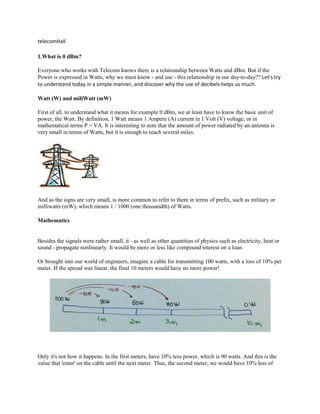
  • 1. telecomHall 1.What is 0 dBm? Everyone who works with Telecom knows there is a relationship between Watts and dBm. But if the Power is expressed in Watts, why we must know - and use - this relationship in our day-to-day?? Let's try to understand today in a simple manner, and discover why the use of decibels helps us much. Watt (W) and miliWatt (mW) First of all, to understand what it means for example 0 dBm, we at least have to know the basic unit of power, the Watt. By definition, 1 Watt means 1 Ampere (A) current in 1 Volt (V) voltage, or in mathematical terms P = VA. It is interesting to note that the amount of power radiated by an antenna is very small in terms of Watts, but it is enough to reach several miles. And as the signs are very small, is more common to refer to them in terms of prefix, such as military or milliwatts (mW), which means 1 / 1000 (one thousandth) of Watts. Mathematics Besides the signals were rather small, it - as well as other quantities of physics such as electricity, heat or sound - propagate nonlinearly. It would be more or less like compound interest on a loan. Or brought into our world of engineers, imagine a cable for transmitting 100 watts, with a loss of 10% per meter. If the spread was linear, the final 10 meters would have no more power! Only it's not how it happens. In the first meters, have 10% less power, which is 90 watts. And this is the value that 'enter' on the cable until the next meter. Thus, the second meter, we would have 10% less of
  • 2. that power or 81 watts (= 90 - 9). Repeating this calculations, you see that in fact the power never reaches zero, as it would if calculations were linear. (At the end of the cable have actually 34.86 Watt) To solve problems o deal with this - and make our lives easier - we need to know the logarithms. We saw this in school, but there are people who do not like to hear. The good thing is that we need not know much about them, just understand what they are. Just understand that if we transformed the magnitudes in logarithms, the calculations become addition and subtraction rather than multiplication and division. Of course, in order to do the calculations by adding and subtracting, we must make the necessary conversions. But with the help of a calculator or Excel, is not that complicated. Decibels (dB) By definition, we have: Sure, we say that working with logarithms (or decibels) is much easier - and the common good. But by the formulas above, still can not understand. So the best way to understand why we use dB (decibels), is seeing how they help us through a practical example.
  • 3. Consider a standard wireless link, where we have a transmitter (1) and a receiver (5), Antennas (3), Cables, Jumpers and Connectors (2) and Free Space (4). Using real values, and without using the help of dB, let's do the math and see, from the transmitted power, how much power we have at receiver. So with dummy values, but close to reality, we have: • Transmitter Power = 40 Watts • Cables and connectors loss = - 0.5 (Half Power) • Antenna Gain = 20 + times in the Power • Free Space Loss = - 0 000 000 000 000 000 1 Power Note: This amount of loss in free space is quite big. And it is obtained based on distance and other factors. For now, just accept that it is a practical value of loss of RF for a given distance of our link. The link with the absolute values in Watt would then be as below. We can work this way, of course. But you must agree that it is not very friendly.
  • 4. Now, if we use the proper conversion of power, gain and loss for dB, we can simply add and subtract. It was so much easier, isn't it? Now we just need to know the formulas to do the conversions. Converting with Formulas in Excel Considering that the amount of wattage is in cell B3, the formula for convrting W in dBm is: = 10 * ( LOG10 ( 1000 * B3 ) ) And the formula to reverse - convert dBm to Watt, considering that our power in dBm is in cell B6 is: = 10 * ( LOG10 ( 1000 * B6 ) ) And as a result, we have calculated values.
  • 5. Note that in case we are using the 1000 value in the formulas, for wearing the Watt, but we want the result in dBm. To calculate (convert) db to ratio, or ratio to db, the formulas do not include the value of 1000. Calculations without using a calculator Of course, we will use calculators in the projects and programs such as Excel. But we also know how to do calculations (conversions) without using a calculator. If anyone tells you that the power is + 46 dBm, you need to know what that means in terms of Watts. For this, there are certain tricks that can be used to arrive at least an approximate match. For this, a good way is to memorize the equivalent to multiplying factors in dB, as in the table below (at least those that are in bold).
  • 6. With the corresponding values of dB and multiplier factor, we convert eg +46 dBm to mW. Answer: First, we expressed 46 values that we already know by heart. So 46 = 10 + 10 + 10 + 10 + 3 + 3 That is, we multiply the reference value (1 mW) for four times the factor of 10 and twice the factor of 2. What gives us 1mW x 10 x 10 x 10 x 10 = 1 000 0 mW 1 000 0 mW x 2 x 2 = 40000 mW = 40 W Ie, + 46 dBm is equal to 40 watts. Conclusion Well, I think now you have given to see that when we do the calculations in dB everything is easier. Moreover, the vast majority of Telecom equipment has specifications of its units in dB (Power, Gain, Loss, etc.). In short, just use basic math to understand the values and reach the final figures.
  • 7. When we say that such a signal is attenuated by 3 dB, means that the final power is half the initial power. Likewise, if a given power is increased by 3 dB means twice the power. A good practice, irrespective of how you will work with the calculations is to store at least some values such as 0 dBm = 1 mWatt (our initial question), 30 dBm = 1 Watt, and in our example, 46 dBm = 40 Watt. So you can quickly learn, for example, the equivalent for the calculations. For example, 43 dBm = 46 dBm - 3 dB. That is, half the power of 46 dbm. Then, 43 dBm = 20 Watts! Just finally, in our example, the received power was - 84 dBm, remember? In this case, doesn't need memorizing. Just so you know which is equivalent to a very low power, but enough for a good example for GSM call. 2. What is VSWR? Everyone has heard at least. Many knows that a bad VSWR affects the performance of the Network. But what about you: do you know what it means, and why we need to know how to use these measures? Today we'll try to see a very simple way what is VSWR. VSWR To understand what is VSWR, we need to talk a little bit about signal propagation in radio frequency systems. Simply put, the radio frequency signals are driven by electric cables between transmitters / receivers to their respective antennas.
  • 8. By its definition, VSWR or Voltage Standing Wave Ratio is a ratio of peak voltage on the minimum amplitude of voltage of standign wave. It does not help much, does it? Okay, let's try to see how it relates ... In radio frequency systems, the characteristic impedance is one of the most important factors to consider. In our case this factor is typically 50 Ohms. This is a constructive parameter, ie is some characteristic determined by its construction. In the case of a cable for example, depends on the size of the inner and outer conductors, and the type of insulation between them. All components of a link - cables, connectors, antennas - are constructed to have the same impedance. When we insert an element in our system, we have what we call the Insertion Loss, which can be understood as something that is lost, taking into account what that actually went in and came out. And this loss occurs in two ways - by Attenuation - especially on cable - and y Reflection. As for the attenuation along the cables, there's not much we can do. Part of the signal is lost along the cable by the generation of heat and also by unwanted radiated off the handle. This loss is characteristic of the same, and defined in terms of dB per lenght unit - the longer the cable is, the greater is the loss. This attenuation also increases with increasing temperature and frequency. Unfortunately, these factors are not much scope of our control, since the frequency is already preset by the system we use, and the temperature will be exposed to climatic variations of where the cable has to pass . The most we can do is try to use cable with less attenuation , ie, cableswith high quality materials used in its construction of the drivers internal and external and insulating dielectric . As a rule, the larger the diameter of the cable, the lower your attenuation. Typical values of diameters are 1/2 ", 7/8" and 1 5/8 ". The choice of coaxial cable for the system is a process that requires a very comprehensive analysis, taking into account its characteristics (is it softer, etc ...) and costs of several options of existing cables, necessary cable length - and the consequent loss that it will introduce, the loading of the tower or brackets where cables will be posted, among others.
  • 9. But the other form of loss that we have in our system, and can be controlled a bit more is the loss by reflection, ie loss of the signal, which has just returned, lost by the end where it was injected. For this reason we call the Return Loss. If there is any problem in the middle between the transmitter / receiver and antennas - such as a fold or infiltration of water - half ends with the impedance mismatch. So, part of the signal which ideally should leave by the antenna, then returns reflected! Speaking in terms of the matching impedances, if the value of X, Y and Z are equal, we have the following. Now with values close to the real impedance unmatched scenario, have the following.
  • 10. If we consider an ideal transmission line, the VSWR would be 1:1, ie all the power to reach your destination, with no reflection (nothing lost). And the worst means of transmission in the world, we would have infinite VSWR, ie all the power would be reflected (lost).