12 - VCB & VMC - Fuji Electric
•
1 recomendación•4,828 vistas

Catalog thiết bị đóng cắt Fuji Electric - 12 - VCB & VMC ********************************************************************* CTY TNHH HẠO PHƯƠNG - Nhà phân phối chính thức các thiết bị điện công nghiệp và tự động hóa của hãng FUJI ELECTRIC JAPAN tại Việt Nam Xem chi tiết các sản phẩm Fuji Electric tại http://haophuong.com/b1033533/fuji-electric

Recomendados
Más contenido relacionado
La actualidad más candente
La actualidad más candente (20)
Destacado
Destacado (20)
Similar a 12 - VCB & VMC - Fuji Electric
Similar a 12 - VCB & VMC - Fuji Electric (20)
Más de CTY TNHH HẠO PHƯƠNG
Más de CTY TNHH HẠO PHƯƠNG (20)
Último
Último (20)
12 - VCB & VMC - Fuji Electric
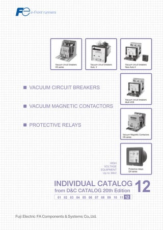
- 1. Information in this catalog is subject to change without notice. 5-7, Nihonbashi Odemma-cho, Chuo-ku, Tokyo, 103-0011, Japan URL http://www.fujielectric.co.jp/fcs/eng INDIVIDUALCATALOGfromD&CCATALOG20thEdition 12 LOW VOLTAGE PRODUCTS Up to 600 Volts Individual catalog No. 01 Magnetic Contactors and Starters Thermal Overload Relays, Solid-state Contactors 02 Industrial Relays, Industrial Control Relays Annunciator Relay Unit, Time Delay Relays Manual Motor Starters and Contactors Combination Starters Pushbuttons, Selector Switches, Pilot Lights Rotary Switches, Cam Type Selector Switches Panel Switches, Terminal Blocks, Testing Terminals Molded Case Circuit Breakers Air Circuit Breakers Earth Leakage Circuit Breakers Earth Leakage Protective Relays Measuring Instruments, Arresters, Transducers Power Factor Controllers Power Monitoring Equipment (F-MPC) Circuit Protectors Low Voltage Current-Limiting Fuses 03 04 05 06 07 08 09 10 HIGH VOLTAGE PRODUCTS Up to 36kV 11 Disconnecting Switches, Power Fuses Air Load Break Switches Instrument Transformers — VT, CT D&C CATALOG DIGEST INDEX AC Power Regulators Noise Suppression Filters Control Power Transformers 12 Vacuum Circuit Breakers, Vacuum Magnetic Contactors Protective Relays Limit Switches, Proximity Switches Photoelectric Switches 01 02 03 04 05 06 07 08 09 10 11 12 INDIVIDUAL CATALOG from D&C CATALOG 20th Edition 12INDIVIDUAL CATALOG from D&C CATALOG 20th Edition 12 VACUUM CIRCUIT BREAKERS PROTECTIVE RELAYS VACUUM MAGNETIC CONTACTORS Vacuum circuit breakers Auto. V Vacuum circuit breakers New-Auto.V Vacuum circuit breakers Multi VCB Vacuum Magnetic Contactors HN series Vacuum circuit breakers HS series HIGH VOLTAGE EQUIPMENT Up to 36kV Protective relays QH series 2010-09 PDF FOLS DEC2012
- 2. Ha Noi Office: No. 95 - TT4, My Dinh Urban Area, My Dinh, Nam Tu Liem, Hanoi. Tel: (84 4) 3568 3740 Fax: (84 4) 3568 3741 Cambodia Office: #140, Room 1-B, St430, Sangkat Toul Tompuong II, Khan Chamkamon, PP. Tel: 855 2322 3635 Fax: 855 2322 3645 Head Office: No 88, Vinh Phu 40, Hoa Long, Vinh Phu, Thuan An, Binh Duong. Tel: (84 650) 37 37 619 Fax: (84 650) 37 37 620 1800 6547 THINK TOGETHER Nhà phân phối thiết bị điện công nghiệp hàng đầu Việt Nam T
- 3. Vacuum Circuit Breakers General information ....................................................................................... 12/1 Advantages .................................................................................................... 12/2 HS series General information.................................................................................... 12/4 Specifications ............................................................................................. 12/5 Types and ratings....................................................................................... 12/11 Installation and accessories....................................................................... 12/14 Dimensions................................................................................................. 12/15 Wiring diagrams ......................................................................................... 12/24 Application guide ........................................................................................ 12/25 Auto. V Specifications ............................................................................................. 12/26 Design features .......................................................................................... 12/27 Types and ratings....................................................................................... 12/29 New-Auto. V ............................................................................................... 12/30 Installation and accessories....................................................................... 12/35 Dimensions................................................................................................. 12/38 Wiring diagrams ......................................................................................... 12/42 Multi VCB Specifications ............................................................................................. 12/45 Types and ratings....................................................................................... 12/47 Installation and accessories....................................................................... 12/48 Dimensions................................................................................................. 12/50 Wiring diagrams ......................................................................................... 12/54 HN series ....................................................................................................... 12/57 QH series General information.................................................................................... 12/66 Dimensions................................................................................................. 12/69 Wiring diagrams ......................................................................................... 12/70 Page 12 H.V.Vacuum circuit breakers Vacuum magnetic contactors Protective relays Vacuum Magnetic Contactors Protective Relays
- 4. MINIMUM ORDERS Orders amounting to less than ¥10,000 net per order will be charged as ¥10,000 net per order plus freight and other charges. WEIGHTS AND DIMENSIONS Weights and dimensions appearing in this catalog are the best information available at the time of going to press. FUJI ELECTRIC FA has a policy of continuous product improvement, and design changes may make this information out of date. Please confirm such details before planning actual construction. INFORMATION IN THIS CATALOG IS SUBJECT TO CHANGE WITHOUT NOTICE.
- 5. Fuji Electric FA Components & Systems Co., Ltd./D & C Catalog Information subject to change without notice 12/1 12 Breaking Rated Rated Closing Type current current voltage system : Installation JIS, JEC (kA) (A) (kV) 20 600 3.6/7.2 Motor-spring HS2006 -06Mf-E 1200 HS2006 -12Mf-E 2000 HS2006 -20Mf-E 25 600 3.6/7.2 HS2506 -06Mf-E 1200 HS2506 -12Mf-E 2000 HS2506 -20Mf-E 31.5 1200 3.6/7.2 HS3106 -12Mf-E 2000 HS3106 -20Mf-E 3000 HS3106 -30Mf-N 40 1200 3.6/7.2 HS4006 -12Mf-E 2000 HS4006 -20Mf-E 3000 HS4006 -30Mf-N 4000 HS4006 -40Mf-N 50 1200 3.6/7.2 HS5006 -12Mf-NA 2000 HS5006 -20Mf-NA 3000 HS5006 -30Mf-N 12.5 600 12 HS1210 -06Mf-E 1200 HS1210 -12Mf-E 2000 HS1210 -20Mf-E 16 600 12 HS1610 -06Mf-E 1200 HS1610 -12Mf-E 2000 HS1610 -20Mf-E 20 600 12 HS2010 -06Mf-E 1200 HS2010 -12Mf-E 2000 HS2010 -20Mf-E 25 600 12 HS2510 -06Mf-E 1200 HS2510 -12Mf-E 2000 HS2510 -20Mf-E 31.5 1200 12 HS3110 -12Mf-E 2000 HS3110 -20Mf-E 3000 HS3110 -30Mf-N ■ FUJI vacuum circuit breakers Vacuum circuit breakers are compact circuit breakers designed for safe operation, high reliability and easy maintenance, and are widely used for various types of high voltage circuits. FUJI V-circuit breakers (VCB) have been developed through the use of our many years of successful experience and advanced technology. They are compact and light-weight, and are available in a number of current ratings. ● HS series These types are available in all ratings from 3.6 to 36kV, and can be applied to a variety of H.V. switchgear. The motor- spring stored-energy types feature auto- reclosing. The HS types are comparatively high in breaking current with ratings of over 7.2kV, 20kA. •Breaking currents: 12.5kA to 50kA • Rated voltage: 3.6kV to 36kV • Standards: JEC, IEC See page 12/4. H.V. Distribution Equipment Vacuum circuit breakers General information ● Auto. V Auto. Vs are provided with a built-in electronic overcurrent relay and toroidal- type CT. They require little space for installation and also facilitate the system wide protective coordination. The inverse-time operating and instantaneous trip currents can be set by means of the dial. • Breaking currents: 8kA, 12.5kA • Rated voltage: 3.6/7.2kV • Standards: JIS C4603 See page 12/26. HS series Multi VCB AF92-31 KK03-058 Auto. V ■ Quick selection table ● Multi VCB The Multi VCBs are general purpose VCBs which are small in size and simple in construction thus allowing them to be applied to many types of switchgear. • Breaking currents: 8kA, 12.5kA • Rated voltage: 3.6/7.2kV • Standards: JIS C4603 See page 12/45. Note: Installation : See pages 12/4 for HS series, 12/26 for Auto. V and 12/45 for Multi VCB. Breaking Rated Rated Closing Type current current voltage system : Installation JIS, JEC (kA) (A) (kV) 40 1200 12 Motor-spring HS4010 -12Mf-NA 2000 HS4010 -20Mf-NA 3000 HS4010 -30Mf-N 4000 HS4010 -40Mf-N 50 1200 12 HS5010 -12Mf-NA 2000 HS5010 -20Mf-NA 3000 HS5010 -30Mf-N 12.5 600 24 HS1220 -06Mf-K 1200 HS1220 -12Mf-K 16 600 24 HS1620 -06Mf-E 1200 HS1620 -12Mf-E 25 600 24 HS2520 -06Mf-E 1200 HS2520 -12Mf-E 2000 HS2520 -20Mf-E 40 1200 24 HS4020 -12Mf-N 2000 HS4020 -20Mf-N 3000 HS4020 -30Mf-N 25 600 36 HS2530 -06Mf-N 1200 HS2530 -12Mf-N 2000 HS2530 -20Mf-N 8.0 400 3.6/7.2 Manual-spring HA08 -H 12.5 600 HA12 -H 8.0 400 3.6/7.2 Motor-spring HA08 -A 12.5 600 Fixed HA12 -A 8.0 400 3.6/7.2 Motor-spring HA08A -A8 12.5 600 Draw-out HA12A -A8 8.0 400 3.6/7.2 Motor-spring HA08 -A 12.5 600 Fixed HA12 -A 8.0 400 3.6/7.2 Motor-spring HA08A -A 12.5 600 Draw-out HA12A -A Discontinued Mar.2007 Discontinued Mar.2007
- 6. Fuji Electric FA Components & Systems Co., Ltd./D & C Catalog Information subject to change without notice12/2 ■ Description 3.6kV to 36kV, 600 to 4000A, 12.5 to 50kA The revolutionary arc extinguishing system ● Rotary FUJI VCBs have employed a unique design principle in which the contacts are provided with a succession of slits having toroidal-type CrCu contacts mounted on them. The arc is driven round the circular contact surface as it is being extinguished. Since the arc is not localized at one point there is no fear of overheating. This results in much improved inter- electrode dielectric strength so ensuring excellent breaking capability. More- over, uneven contact wear is minimized. ● Getter FUJI vacuum interrupters make use of the gettering effect. The toroidal-type contacts are made of a special chromium-copper (CrCu) alloy specially developed by FUJI so as to ensure a large “getter” quality. The metallic gases thus produced at interruption and left in the vacuum are quickly absorbed by the getter. The gases are neutralized so maintaining the high degree of vacuum. The interrupters require a minimum of attention over their long service life. ● Surge Switching surges can be generated at small current breaking due to the VCB inherent chopping current. FUJI has paid much attention to this problem, and after much effort on design and materials research it has been possible to reduce the chopping current to 3.5 Amps. This very small chopping current means that the corresponding surge voltage will be reduced and cost efficient surge protection can be carried out for motors, transformers and other load equipment. H.V. Distribution Equipment Vacuum circuit breakers Advantages The revolutionary arc extinguishing system Stationary contact Slits Toroidal-type CrCu contacts Arc flow Moving contact Cover Stainless steel bellows Stationary contact Ceramic tube Moving contact Bellows Shield
- 7. Fuji Electric FA Components & Systems Co., Ltd./D & C Catalog Information subject to change without notice 12/3 12 H.V. Distribution Equipment Vacuum circuit breakers Advantages ● Progress of arc extinction Arcs generated by VCBs have inherent characteristics that change when approximately 10kA is reached. Less than 10kA a dispersed arc occurs, over this value the arc is concentrated. The photos were taken consecutively and illustrate an interruption in the 25kA range (concentrated arc). About 41/2 rotations occurred (10ms at 50Hz). This time is typical, but varies according to breaking current and arcing times. Explanation 1. The contacts begin to open and the arc moves from the center to the left hand side. 2. 3. The arc is driven round the toroidal-type contact surface. 4. The contacts are in the full open position just before interruption is completed. ■ Definitions ● What is the action of the “getter”? Sometimes called a “degasser” the “getter” uses a special material such as zirconium alloy that has the property of absorbing metallic gases in a vacuum. This allows the high degree of vacuum to be maintained. ● Switching surges and VCBs? Switching surges can be generated when breaking currents within several hundreds range. VCB inherent switching surges are generated under certain specific conditions which mainly comprise current chopping surges and multiple current reignition surges. No problem is posed by switching surges when breaking current exceeds several hundred amperes. Surge voltages The value of the surge voltage due to switching surges varies according to the load circuit conditions. This can be expressed in the following simple formula: Surge voltage = Surge impedance ✕ Chopping current Therefore, it is necessary to keep the chopping current low in order to reduce the surge voltage to the minimum. The peak transient voltage is obtained by adding to the above calculation the voltage on the load side at the time of current chopping. Chopping surge The chopping surge occurs when a low current is interrupted, the arc is unstable before current becomes zero and the current is forcedly chopped. At this time a surge is generated by the energy remaining in the load inductance. Example: When the no-load interruption of a transformer is carried out the exciting current only is interrupted. Chopping surge Multiple reignition surge The multiple reignition surges can occur when breaking currents range from tens to hundreds of amperes. Although no problem is normally posed even when breaking these currents, ↑ 1* 2* Current chopping surge Multiple reignition surge Chopping current 0 Ic Several tens of amps. Several hundreds of amps. Breaking current, Amps 1* Chopping surge suppresed by reignition 2* Chopping surge not accompanied with reignition Chopping current HIGH IC : Chopping current Vl : Voltage at load side VS : Surge transient voltage VP : Peak transient voltage VP= Vl + Vs VS= Surge impedance × IC Surge impedance: Chopping current LOW VCB Natural current zero FUJI VCB Others Vp Vp Ic Vs Vs Vl Vl Vl I R C L Z= L C Switching surge 1 2 3 4 a high surge voltage can be generated when breaking an inrush current on starting the motors.
- 8. Fuji Electric FA Components & Systems Co., Ltd./D & C Catalog Information subject to change without notice12/4 ■ Description HS type 3.6kV to 36kV up to 63kA. FUJI HS series vacuum circuit breakers are designed to meet the many special needs of industry. The vacuum interrupter system employed reflects the latest technology. The circuit breaker has a very stable and constant breaking performance over a wide range of currents up to the rated short circuit current value. The motor spring type (M) closing system can perform high speed reclosing. The contacts are made of a special alloy and require no maintenance over their long life time. The interrupter is provided with a contact-wear indicator which gives notice when replacement is required. The open and close positioning indicator, operating counter, pushbutton for manual interruption and manual closing device are conveniently installed on the control section of the dead-front operating panel, and are isolated from the high-voltage breaking section for safety reasons and to facilitate operation and inspection. FUJI VCBs comprise the fixed mounted (P) type and cradle (X and Y) types. Since the cradle version is provided with a draw-out system switchgear assembly is easily carried out. ■ Ordering information Specify the following: 1. Type number 2. Rated voltage, current and frequency 3. Rated breaking capacity 4. Installation system 5. Operating voltage and frequency (M) of closing system 6. Voltage and current of tripping system 7. Optional accessories, if required H.V. Distribution Equipment Vacuum circuit breakers HS series/General information Installation P : Fixed type X : Draw-out type with cradle for JEM1425 Class CW U : Draw-out type with cradle for JEM1425 Class CW Y : Draw-out type with cradle and shutter for JEM1425 MW, PW M: Draw-out type for HS2530 Series of FUJI VCB Rated voltage Breaking current 3.6kV 7.2kV 12kV 24kV 36kV ■ Type number nomenclature Basic type HS: 7.2kV 12.5kA and over Rated breaking current 12: 12.5kA 31: 31.5kA 16: 16kA 40: 40kA 20: 20kA 50: 50kA 25: 25kA 63: 63kA Rated voltage 06: 3.6/7.2kV 20: 24kV 10: 12kV 30: 36kV HS 20 06 M- 06 M f Tripping system f : Shunt trip Specify the frequency and voltage (AC or DC) Closing system M: Motor-spring stored energy (High speed reclosing) Specify the frequency and voltage (AC or DC) Rated current 06: 600, 630A 20: 2000A 12: 1200, 1250A 30: 3000A 40: 4000A AF96-31 12.5kA – HS1210: 600A – HS1220: 600A – 1200A, 2000A 1200A 16kA – HS1610: 600A HS1615: 600A, HS1620: 600A – 1200A, 2000A 1200A, 2000A 1200A 20kA HS2006: 600A HS2010: 600A HS2015: 600A, – – 1200A, 2000A 1200A, 2000A 1200A, 2000A 25kA HS2506: 600A HS2510: 600A HS2515: 600A, HS2520: 600A HS2530: 600A 1200A, 2000A 1200A, 2000A 1200A, 2000A 1200A, 2000A 1200A, 2000A 31.5kA HS3106: 1200A HS3110: 1200A HS3115: 600A, – – 2000A, 3000A 2000A, 3000A 1200A, 2000A 40kA HS4006: 1200A HS4010: 1200A HS4015: 600A, HS4020: 1200A – 2000A, 3000A, 2000A, 3000A 1200A, 2000A 2000A, 3000A 4000A4000A 50kA HS5006: 1200A, HS5010: 1200A – – – 2000A, 3000A 2000A, 3000A 63kA HS6306: 1200A, – – – – 2000A 15kV
- 9. Fuji Electric FA Components & Systems Co., Ltd./D & C Catalog Information subject to change without notice 12/5 12 Type HS2006 HS2506 HS3106 -■Mf-E -■Mf-E -■Mf-E Rated voltage [kV] 3.6 7.2 3.6 7.2 3.6 7.2 Rated current [A] JEC 600, 1200 600, 1200 1200, 2000, 3000 ■ :06, 12, 20, 30 2000 2000 IEC 630, 1250 630, 1250 1250, 2000, 3000 2000 2000 Rated breaking capacity [kA] 20 25 31.5 [MVA] Ref. value 125 250 160 310 200 390 Rated short-circuit making current [kA] 50 63 80 Rated short-time JEC: 2 sec. 20 25 31.5 withstand current [kA] IEC: 1 sec. *1 20 25 31.5 Rated breaking time [cycle] 3 3 3 Rated Power frequency JEC [kV] 22 22 22 withstand (1 min.) IEC [kV] 20 20 20 voltage Impulse (1.2×50µs) [kV] 60 60 60 Closing time at no load [sec] 0.04 0.04 0.04 (3000A: 0.05) Rated operating sequence JEC O-1min-CO-3min-CO, CO-15s-CO or O-0.35s-CO-1min-CO IEC O-3min-CO-3min-CO, CO-15s-CO or O-0.3s-CO-3min-CO Opening time [sec.] JEC 0.03 0.03 0.03 IEC 0.03 0.03 0.03 Closing system Motor-spring stored energy (High speed reclosing) (M) Operating voltage and current for closing 100V AC/DC, 1.7A*3 100V AC/DC, 2A 100V AC/DC, 2.5A 200V AC/DC, 1A 200V AC/DC, 1A 200V AC/DC, 1.7A Control voltage and current for closing 100V AC/DC, 4A 100V AC/DC, 4A 100V AC/DC, 5A 200V AC/DC, 2A 200V AC/DC, 2A 200V AC/DC, 2.5A Tripping system*2 Shunt trip (f) Operating voltage and current for tripping 100V DC, 4A 100V DC, 4A 200V DC, 2A 200V DC, 2A Auxiliary contact 4NO+4NC, Rating 100/200V AC: 20/10A, 100/200V DC: 5/3A Durability Mechanical [operations] 10000 Electrical [operations] 10000 Installation P, Y P, Y P, Y X, U (600, 1200A only) X, U (600, 1200A only) X (1200, 2000A only) Mass (draw-out type without cradle)[kg] 62 (X, U, Y: 600A) 66 (X, U, Y: 600A) 122 (X, Y: 1200A) 66 (Y: 1200A) 70 (Y: 1200A) 130 (X, Y: 2000A) 117 (Y: 2000A) 117 (Y: 2000A) 220 (Y: 3000A) H.V. Distribution Equipment Vacuum circuit breakers HS series ■ Specifications Notes: *1 Contact FUJI for the information concerning the 3 sec. rating of IEC. *2 If capacitor tripping system is required, connect a capacitor trip device VCB-T1A or VCB-T2A (optional accessory) to AC power supply. *3 2A for 2000A rating.
- 10. Fuji Electric FA Components & Systems Co., Ltd./D & C Catalog Information subject to change without notice12/6 Type HS4006 HS4006 HS5006 HS5006 HS6306 -■Mf-E -40Mf-N -■Mf-NA -30Mf-N -■Mf-NB Rated voltage [kV] 3.6 7.2 3.6 7.2 3.6 7.2 3.6 7.2 3.6 7.2 Rated current [A] JEC 1200, 2000, 3000 4000 1200, 2000 3000 1200, 2000 ■: 12, 20, 30 IEC 1250, 2000, 3000 4000 1250, 2000 3000 1250, 2000 Rated breaking capacity [kA] 40 40 50 50 63 [MVA] Ref. value 250 500 250 500 310 620 310 620 390 780 Rated short-circuit making current [kA] 100 100 125 125 160 Rated short-time JEC: 2 sec. 40 40 50 50 63 withstand current [kA] IEC: 1 sec. *1 40 40 50 50 63 Rated breaking time [cycle] 5 5 5 5 5 Rated Power frequency JEC [kV] 22 22 22 22 22 withstand (1 min.) IEC [kV] 20 20 20 20 20 voltage Impulse (1.2×50µs) [kV] 60 60 60 60 60 Closing time at no load [sec] 0.04(3000A: 0.05) 0.1 0.1 0.1 0.1 Rated operating sequence JEC O-1min-CO-3min-CO, CO-15s-CO or O-0.35s-CO-1min-CO IEC O-3min-CO-3min-CO, CO-15s-CO or O-0.3s-CO-3min-CO Opening time [sec.] JEC 0.03 0.07 0.07 0.07 0.07 IEC 0.04 0.07 0.07 0.07 0.07 Closing system Motor-spring stored energy (High speed reclosing) (M) Operating voltage and current for closing 100V AC/DC, 2.5A 100V AC/DC, 6A 100V AC/DC, 6A 100V AC/DC, 6A 100V AC/DC, 6A 200V AC/DC, 1.7A 200V AC/DC, 3A 200V AC/DC, 3A 200V AC/DC, 3A 200V AC/DC, 3A Control voltage and current for closing 100V AC/DC, 5A 100V AC/DC, 4A 100V AC/DC, 4A 100V AC/DC, 4A 100V AC/DC, 4A 200V AC/DC, 2.5A 200V AC/DC, 2A 200V AC/DC, 2A 200V AC/DC, 2A 200V AC/DC, 2A Tripping system *2 Shunt trip (f) Operating voltage and current for tripping 100V DC, 4A: JEC 100V DC, 4A 3A: IEC 200V DC, 2A 200V DC, 2A: JEC 1.5A:IEC Auxiliary contact 4NO+4NC, Rating 100/200V AC: 20/10A, 100/200V DC: 5/3A Durability Mechanical [operations] 10000 Electrical [operations] 10000 Installation P, Y P, X, Y P, Y P, Y Y X (1200, 2000A only) Mass (draw-out type without cradle) [kg] 122 (X, Y: 1200A) 400 240 320 350 130 (X, Y: 2000A) 220 (Y: 3000A) H.V. Distribution Equipment Vacuum circuit breakers HS series ■ Specifications Notes: *1 Contact FUJI for the information concerning the 3 sec. rating of IEC. *2 If capacitor tripping system is required, connect a capacitor trip device VCB-T1A or VCB-T2A (optional accessory) to AC power supply.
- 11. Fuji Electric FA Components & Systems Co., Ltd./D & C Catalog Information subject to change without notice 12/7 12 ■ Specifications Type HS1210 HS1610 HS2010 HS2510 HS3110 -■Mf-E -■Mf-E -■Mf-E -■Mf-E -■Mf-E Rated voltage [kV] 12 12 12 12 12 Rated current [A] JEC 600, 1200 600, 1200 600, 1200 600, 1200 1200, 2000 ■: 06, 12, 20 2000 2000 2000 2000 IEC 630, 1250 630, 1250 630, 1250 630, 1250 1250, 2000 2000 2000 2000 2000 Rated breaking capacity [kA] 12.5 16 20 25 31.5 [MVA] Ref. value 260 330 415 520 650 Rated short-circuit making current [kA] 31.5 40 50 63 80 Rated short-time JEC: 2 sec. 12.5 16 20 25 31.5 withstand current [kA] IEC: 1 sec. *1 12.5 16 20 25 31.5 Rated breaking time [cycle] 3 3 3 3 3 Rated Power frequency JEC [kV] 28 28 28 28 28 withstand (1 min.) IEC [kV] 28 28 28 28 28 voltage Impulse (1.2×50µs) [kV] 75 75 75 75 75 Closing time at no load [sec.] 0.04 0.04 0.04 0.04 0.04 Rated operating sequence JEC O-1min-CO-3min-CO, CO-15s-CO or O-0.35s-CO-1min-CO IEC O-3min-CO-3min-CO, CO-15s-CO or O-0.3s-CO-3min-CO Opening time [sec.] JEC 0.03 0.03 0.03 0.03 0.03 IEC 0.03 0.03 0.03 0.03 0.03 Closing system Motor-spring stored energy (High speed reclosing) (M) Operating voltage and current for closing 100V AC/DC, 1.7A (600, 1200A), 2.5A (2000A) 100V AC/DC, 2.5A 200V AC/DC, 1A (600, 1200A), 1.7A (2000A) 200V AC/DC, 1.7A Control voltage and current for closing 100V AC/DC, 4A (600, 1200A), 5A (2000A) 100V AC/DC, 5A 200V AC/DC, 2A (600, 1200A), 2.5A (2000A) 200V AC/DC, 2.5A Tripping system*2 Shunt trip (f) Operating voltage and current for tripping 100V DC, 4A 100V DC, 4A 200V DC, 2A 200V DC, 2A Auxiliary contact 4NO+4NC, Rating 100/200V AC: 20/10A, 100/200V DC: 5/3A Durability Mechanical [operations] 10000 Electrical [operations] 10000 Installation P, Y P, Y P, Y P, Y P, X, Y X (600, 1200A only) X (600, 1200A only) X (600, 1200A only) X (600, 1200A only) Mass (draw-out type, without cradle) [kg] 71 (Y: 600A) 71 (Y: 600A) 71 (Y: 600A) 75 (Y: 600A) 122 (X, Y: 1200A) 71 (Y: 1200A) 71 (Y: 1200A) 71 (Y: 1200A) 75 (Y: 1200A) 130 (X, Y: 2000A) 130 (X, Y: 2000A) 130 (X, Y: 2000A) 130 (X, Y: 2000A) 130 (X, Y: 2000A) Notes: *1 Contact FUJI for the information concening the 3 sec. rating of IEC. *2 If capacitor tripping system is required, connect a capacitor trip device VCB-T1A or VCB-T2A (optional accessory) to an AC power supply. H.V. Distribution Equipment Vacuum circuit breakers HS series
- 12. Fuji Electric FA Components & Systems Co., Ltd./D & C Catalog Information subject to change without notice12/8 Type HS3110 HS4010 HS4010 HS5010 HS5010 -30Mf-N -■Mf-NA -■Mf-N -■Mf-NA -30Mf-N Rated voltage [kV] 12 12 12 12 12 Rated current [A] JEC 3000 1200, 2000 3000, 4000 1200, 2000 3000 ■: 12, 20, 30, 40 IEC 3000 1250, 2000 3000, 4000 1250, 2000 3000 Rated breaking capacity [kA] 31.5 40 40 50 50 [MVA] Ref. value 650 830 830 1040 1040 Rated short-circuit making current [kA] 80 100 100 125 125 Rated short-time JEC: 2 sec. 31.5 40 40 50 50 withstand current [kA] IEC: 1 sec. *1 31.5 40 40 50 50 Rated breaking time [cycle] 3 5 5 5 5 Rated Power frequency JEC [kV] 28 28 28 28 28 withstand (1 min.) IEC [kV] 28 28 28 28 28 voltage Impulse (1.2×50µs) [kV] 75 75 75 75 75 Closing time at no load [sec.] 0.1 0.1 0.1 0.1 0.1 Rated operating sequence JEC O-1min-CO-3min-CO, CO-15s-CO or O-0.35s-CO-1min-CO IEC O-3min-CO-3min-CO, CO-15s-CO or O-0.3s-CO-3min-CO Opening time [sec.] JEC 0.04 0.04 0.04*3 0.07 0.07 IEC 0.04 0.04 0.04*3 0.07 0.07 Closing system Motor-spring stored energy (High speed reclosing) (M) Operating voltage and current for closing 100V AC/DC, 6A 200V AC/DC, 3A Control voltage and current for closing 100V AC/DC, 4A 200V AC/DC, 2A Tripping system*2 Shunt trip (f) Operating voltage and current for tripping 100V DC, 4A 200V DC, 2A Auxiliary contact 4NO+4NC, Rating 100/200V AC: 20/10A, 100/200V DC: 5/3A Durability Mechanical [operations] 10000 Electrical [operations] 10000 Installation P, Y P, Y P, Y(3000A) P, Y P, Y X(4000A) Mass (draw-out type without cradle) [kg] 320 240 320 (3000A) 240 320 400 (4000A) H.V. Distribution Equipment Vacuum circuit breakers HS series ■ Specifications Notes: *1 Contact FUJI for the information concerning the 3 sec. rating of IEC. *2 If capacitor tripping system is required, connect a capacitor trip device VCB-T1A or VCB-T2A (optional accessory) to AC power supply. *3 0.07s for 4000A rating.
- 13. Fuji Electric FA Components & Systems Co., Ltd./D & C Catalog Information subject to change without notice 12/9 12 Discontinued Mar. 2007 Type HS1215 HS1615 HS2015 HS2515 HS3115 HS4015 -■Mf-N -■Mf-N -■Mf-N -■Mf-N -■Mf-N -■Mf-N Rated voltage [kV] 15 15 15 15 15 15 Rated current [A] JEC 600, 1200 600, 1200 600, 1200 600, 1200 1200 1200 ■: 06, 12, 20, 30 2000 2000 2000 2000 2000, 3000 2000, 3000 IEC 630, 1250 630, 1250 630, 1250 630, 1250 1250 1250 2000 2000 2000 2000 2000, 3000 2000, 3000 Rated breaking capacity [kA] 12.5 16 20 25 31.5 40 [MVA] Ref. value 325 415 520 650 820 1040 Rated short-circuit making current [kA] 31.5 40 50 63 80 100 Rated short-time JEC: 2 sec. 12.5 16 20 25 31.5 40 withstand current [kA] IEC: 1 sec. *1 12.5 16 20 25 31.5 40 Rated breaking time [cycle] 3 3 3 3 3 5 Rated Power frequency JEC [kV] – – – – – – withstand (1 min.) IEC [kV] 36 36 36 36 36 36 voltage Impulse (1.2×50µs) [kV] 95 95 95 95 95 95 Closing time at no load [sec.] 0.1 0.1 0.1 0.1 0.1 0.1 Rated operating sequence JEC O-1min-CO-3min-CO, CO-15s-CO or O-0.35s-CO-1min-CO IEC O-3min-CO-3min-CO, CO-15s-CO or O-0.3s-CO-3min-CO Opening time [sec.] JEC 0.03 0.03 0.03 0.03 0.04 0.04 IEC 0.03 0.03 0.03 0.03 0.04 0.04 Closing system Motor-spring stored energy (High speed reclosing) (M) Operating voltage and current for closing 100V AC/DC, 1.3A 100V AC/DC, 6A 200V AC/DC, 0.8A 200V AC/DC, 3A Control voltage and current for closing 100V AC/DC, 5A 100V AC/DC, 4A 200V AC/DC, 3A 200V AC/DC, 2A Tripping system *2 Shunt trip (f) Operating voltage and current for tripping 100V DC, 4A 200V DC, 2A Auxiliary contact 4NO+4NC, Rating 100/200V AC: 20/10A, 100/200V DC: 20/10A Durability Mechanical [operations] 10000 Electrical [operations] 10000 Installation P, X, Y P, X, Y P, X, Y P, X, Y P, Y P, Y Mass (draw-out type without cradle) [kg] 130 (600A) 130 (600A) 130 (600A) 130 (600A) 195 (1200A) 260 (1200A) 130 (1200A) 130 (1200A) 130 (1200A) 130 (1200A) 195 (2000A) 260 (2000A) 140 (2000A) 140 (2000A) 140 (2000A) 140 (2000A) 320 (3000A) 320 (3000A) ■ Specifications Notes: *1 Contact FUJI for the information concerning the 3 sec. rating of IEC. *2 If capacitor tripping system is required, connect a capacitor trip device VCB-T1A or VCB-T2A (optional accessory) to AC power supply. H.V. Distribution Equipment Vacuum circuit breakers HS series
- 14. Fuji Electric FA Components & Systems Co., Ltd./D & C Catalog Information subject to change without notice12/10 H.V. Distribution Equipment Vacuum circuit breakers HS series Type HS1220 HS1620 HS2520 HS4020 HS2530 -■Mf-K -■Mf-E -■Mf-E -■Mf-N -■Mf-N Rated voltage [kV] 24 24 24 24 36 Rated current [A] JEC 600, 1200 600, 1200 600, 1200 1200, 2000 600, 1200 ■: 06, 12, 20, 30 2000 3000 2000 IEC 630, 1250 630, 1250 630, 1250 1250, 2000 630, 1250 2000 3000 2000 Rated breaking capacity [kA] 12.5 16 25 40 25 [MVA] Ref. value 520 665 1000 1660 1600 Rated short-circuit making current [kA] 31.5 40 63 100 63 Rated short-time JEC: 2 sec. 12.5 16 25 40 25 withstand current [kA] IEC: 1 sec. *1 12.5 16 25 40 25 Rated breaking time [cycle] 3 3 3 5 3 Rated Power frequency JEC [kV] 50 50 50 50 70 withstand (1 min.) IEC [kV] 50 50 50 50 70 voltage Impulse (1.2×50µs) [kV] 125 125 125 125 170 Closing time at no load [sec.] 0.04 0.04 0.04 0.1 0.1 Rated operating sequence JEC O-1min-CO-3min-CO, CO-15s-CO or O-0.35s-CO-1min-CO IEC O-3min-CO-3min-CO, CO-15s-CO or O-0.3s-CO-3min-CO Opening time [sec.] JEC 0.03 0.03 0.03 0.07 0.04 IEC 0.03 0.03 0.03 0.07 0.04 Closing system Motor-spring stored energy (High speed reclosing) (M) Operating voltage and current for closing 100V AC/DC, 2A 100V AC/DC, 2.5A 100V AC/DC, 6A 200V AC/DC, 1A 200V AC/DC, 1.7A 200V AC/DC, 3A Control voltage and current for closing 100V AC/DC, 4A 100V AC/DC, 5A 100V AC/DC, 4A 200V AC/DC, 2A 200V AC/DC, 2.5A 200V AC/DC, 2A Tripping system *2 Shunt trip (f) Operating voltage and current for tripping 100V DC, 4A 200V DC, 2A Auxiliary contact 4NO+4NC, Rating 100/200V AC: 20/10A, 100/200V DC: 20/10A Durability Mechanical [operations] 10000 Electrical [operations] 10000 Installation P, X, Y P, X, Y P, X, Y P, Y P, M, X Mass (draw-out type without cradle) [kg] 120 (P, X: 600A) 120 (P, X: 600A) 190 (Y: 600A) 280 (1200A) 280 (M, X: 600A) 130 (P, X: 1200A) 130 (P, X: 1200A) 190 (Y: 1200A) 280 (2000A) 280 (M, X: 1200A) 150 (Y) 150 (Y) 200 (Y: 2000A) 350 (3000A) 300 (M, X: 2000A) ■ Specifications Notes: *1 Contact FUJI for the information concerning the 3 sec. rating of IEC. *2 If capacitor tripping system is required, connect a capacitor trip device VCB-T1A or VCB-T2A (optional accessory) to AC power supply.
- 15. Fuji Electric FA Components & Systems Co., Ltd./D & C Catalog Information subject to change without notice 12/11 12 HS2006 -06Mf-E HS2006 -12Mf-E HS2006 -20Mf-E HS2506 -06Mf-E HS2506 -12Mf-E HS2506 -20Mf-E HS3106 -12Mf-E HS3106 -20Mf-E HS3106 -30Mf-E HS4006 -12Mf-E HS4006 -20Mf-E HS4006 -30Mf-E HS4006 -40Mf-N HS5006 -12Mf-NA HS5006 -20Mf-NA HS5006 -30Mf-N HS6306 -12Mf-NB HS6306 -20Mf-NB ■ Types and ratings, 3.6/7.2kV Rating Volts Breaking Current current (kV) (kA) (A) Closing system Tripping Closing Operating voltage system voltage Shunt-trip(f) *2 Type M 100/110V DC 100/110V DC M 100/110V DC 100/110V DC M 100/110V DC 100/110V DC M 100/110V DC 100/110V DC M 100/110V DC 100/110V DC M 100/110V DC 100/110V DC M 100/110V DC 100/110V DC M 100/110V DC 100/110V DC M 100/110V DC 100/110V DC M 100/110V DC 100/110V DC M 100/110V DC 100/110V DC M 100/110V DC 100/110V DC M 100/110V DC 100/110V DC M 100/110V DC 100/110V DC M 100/110V DC 100/110V DC M 100/110V DC 100/110V DC M 100/110V DC 100/110V DC M 100/110V DC 100/110V DC 3.6/7.2 20 600 1200 2000 25 600 1200 2000 31.5 1200 2000 3000 40 1200 2000 3000 4000 50 1200 2000 3000 63 1200 2000 Notes: *1 Installation system P: Fixed type X: Draw-out type with cradle for JEM 1425 Class CW U: Draw-out type with cradle for JEM 1425 Class CW Y: Draw-out type with cradle and shutter for JEM 1425 Class MW, PW *2 Closing system M: Motor-spring stored-energy (High speed reclosing) : Avaiable installation system *1 Ordering code P, X, U, Y P, X, U, Y P, X, Y P, X, Y P, X P, Y Y H.V. Distribution Equipment Vacuum circuit breakers HS series HS1210 -06Mf-E HS1210 -12Mf-E HS1210 -20Mf-E HS1610 -06Mf-E HS1610 -12Mf-E HS1610 -20Mf-E HS2010 -06Mf-E HS2010 -12Mf-E HS2010 -20Mf-E ■ Types and ratings, 12kV Rating Volts Breaking Current current (kV) (kA) (A) Closing system Tripping Closing Operating voltage system voltage Shunt-trip(f) *2 Type M 100/110V DC 100/110V DC M 100/110V DC 100/110V DC M 100/110V DC 100/110V DC M 100/110V DC 100/110V DC M 100/110V DC 100/110V DC M 100/110V DC 100/110V DC M 100/110V DC 100/110V DC M 100/110V DC 100/110V DC M 100/110V DC 100/110V DC 12 12.5 600 1200 2000 16 600 1200 2000 20 600 1200 2000 : Avaiable installation system *1 Ordering code P, X, Y P, X, Y P, X, Y Notes: *1 Installation system P: Fixed type X: Draw-out type with cradle for JEM 1425 Class CW Y: Draw-out type with cradle and shutter for JEM 1425 Class MW, PW *2 Closing system M: Motor-spring stored-energy (High speed reclosing)
- 16. Fuji Electric FA Components & Systems Co., Ltd./D & C Catalog Information subject to change without notice12/12 Discontinued Mar. 2007 H.V. Distribution Equipment Vacuum circuit breakers HS series Notes: *1 Installation system P: Fixed type X: Draw-out type with cradle for JEM 1425 Class CW Y: Draw-out type with cradle and shutter for JEM 1425 Class MW, PW *2 Closing system M: Motor-spring stored-energy (High speed reclosing) HS2510 -06Mf-E HS2510 -12Mf-E HS2510 -20Mf-E HS3110 -12Mf-E HS3110 -20Mf-E HS3110 -30Mf-N HS4010 -12Mf-NA HS4010 -20Mf-NA HS4010 -30Mf-N HS4010 -40Mf-N HS5010 -12Mf-NA HS5010 -20Mf-NA HS5010 -30Mf-N ■ Types and ratings, 12kV Rating Volts Breaking Current current (kV) (kA) (A) Closing system Tripping Closing Operating voltage system voltage Shunt-trip(f) *2 Type M 100/110V DC 100/110V DC M 100/110V DC 100/110V DC M 100/110V DC 100/110V DC M 100/110V DC 100/110V DC M 100/110V DC 100/110V DC M 100/110V DC 100/110V DC M 100/110V DC 100/110V DC M 100/110V DC 100/110V DC M 100/110V DC 100/110V DC M 100/110V DC 100/110V DC M 100/110V DC 100/110V DC M 100/110V DC 100/110V DC M 100/110V DC 100/110V DC 12 25 600 1200 2000 31.5 1200 2000 3000 40 1200 2000 3000 4000 50 1200 2000 3000 : Avaiable installation system *1 Ordering code P, X, Y P, X, Y P, Y P, Y P, Y X P, Y Notes: *1 Installation system P: Fixed type X: Draw-out type with cradle for JEM 1425 Class CW Y: Draw-out type with cradle and shutter for JEM 1425 Class MW, PW *2 Closing system M: Motor-spring stored-energy (High speed reclosing) HS1215 -06Mf-N HS1215 -12Mf-N HS1215 -20Mf-N HS1615 -06Mf-N HS1615 -12Mf-N HS1615 -20Mf-N HS2015 -06Mf-N HS2015 -12Mf-N HS2015 -20Mf-N HS2515 -06Mf-N HS2515 -12Mf-N HS2515 -20Mf-N HS3115 -12Mf-N HS3115 -20Mf-N HS3115 -30Mf-N HS4015 -12Mf-N HS4015 -20Mf-N HS4015 -30Mf-N ■ Types and ratings, 15kV Rating Volts Breaking Current current (kV) (kA) (A) Closing system Tripping Closing Operating voltage system voltage Shunt-trip(f) *2 Type M 100/110V DC 100/110V DC M 100/110V DC 100/110V DC M 100/110V DC 100/110V DC M 100/110V DC 100/110V DC M 100/110V DC 100/110V DC M 100/110V DC 100/110V DC M 100/110V DC 100/110V DC M 100/110V DC 100/110V DC M 100/110V DC 100/110V DC M 100/110V DC 100/110V DC M 100/110V DC 100/110V DC M 100/110V DC 100/110V DC M 100/110V DC 100/110V DC M 100/110V DC 100/110V DC M 100/110V DC 100/110V DC M 100/110V DC 100/110V DC M 100/110V DC 100/110V DC M 100/110V DC 100/110V DC 15 12.5 600 1200 2000 16 600 1200 2000 20 600 1200 2000 25 600 1200 2000 31.5 1200 2000 3000 40 1200 2000 3000 : Avaiable installation system *1 Ordering code P, X, Y P, X, Y P, X, Y P, X, Y P, Y P, Y
- 17. Fuji Electric FA Components & Systems Co., Ltd./D & C Catalog Information subject to change without notice 12/13 12 HS1220 -06Mf-K HS1220 -12Mf-K HS1620 -06Mf-E HS1620 -12Mf-E HS2520 -06Mf-E HS2520 -12Mf-E HS2520 -20Mf-E HS4020 -12Mf-N HS4020 -20Mf-N HS4020 -30Mf-N HS2530 -06Mf-N HS2530 -12Mf-N HS2530 -20Mf-N ■ Types and ratings, 24kV and 36kV Rating Volts Breaking Current current (kV) (kA) (A) Closing system Tripping Closing Operating voltage system voltage Shunt-trip(f) *2 Type M 100/110V DC 100/110V DC M 100/110V DC 100/110V DC M 100/110V DC 100/110V DC M 100/110V DC 100/110V DC M 100/110V DC 100/110V DC M 100/110V DC 100/110V DC M 100/110V DC 100/110V DC M 100/110V DC 100/110V DC M 100/110V DC 100/110V DC M 100/110V DC 100/110V DC M 100/110V DC 100/110V DC M 100/110V DC 100/110V DC M 100/110V DC 100/110V DC 24 12.5 600 1200 16 600 1200 25 600 1200 2000 40 1200 2000 3000 36 25 600 1200 2000 : Avaiable installation system *1 Ordering code P, X, Y P, X, Y P, X, Y P, Y P, M, X Notes: *1 Installation system P: Fixed type X: Draw-out type with cradle for JEM 1425 Class CW Y: Draw-out type with cradle and shutter for JEM 1425 Class MW, PW M: Draw-out type for HS2530 *2 Closing system M: Motor-spring stored-energy (High speed reclosing) H.V. Distribution Equipment Vacuum circuit breakers HS series
- 18. Fuji Electric FA Components & Systems Co., Ltd./D & C Catalog Information subject to change without notice12/14 H.V. Distribution Equipment Vacuum circuit breakers HS series ■ Installation and supplied accessories Vacuum circuit breaker Cradle Construction Accessories P-fixed mounting type X-draw-out type Y-draw-out type AF93-312 AF93-314 AF93-313 The VCB shall be fixed to the switchgear by means of 4 bolts. No draw-out system is provided. Wheels are provided to facilitate movement or transport. Open type cubicle • Clamp bolts (4 ea. for one unit) • Closing handle • Plug-in connector for control circuit • On-off counter A cradle is provided with a draw-out system. This cradle makes unnecessary the provision of rails or main circuit connector for the switchgear. No mechanical adjustment is required. JEM 1425 Class CW type metal enclosure • On-off counter • Cradle with draw-out system (Main circuit connector, earthing shoe, rail, etc.) • Plug-in connector • Closing handle • Draw-out handle A cradle is provided with a draw-out system to accept the metal-clad switchgear, which is provided with a shutter. All the necessary parts are provided for this type of breaker. The switchgear is very easy to assemble. JEM 1425 Class PW or MW type metal-clad switchgear • On-off counter • Cradle with draw-out system (Main circuit connector, earthing shoe, rail, shutter, etc.) • Plug-in connector • Closing handle • Draw-out handle SF-877 SF-1055 ■ Optional accessories This is used when the trip circuit is connected to an AC power supply, and as well as the capacitor, semiconductors are also built in. It provides a DC output and the trip coil is DC rated. Capacitor trip device/VCB-T1A, T2A Lifting dolly L-2HS, L-4HS Type Description VCB-T1A Capacitor trip device 100/110V AC VCB-T2A Capacitor trip device 200/220V AC AF3320R3TXG0542 C-R surge absorber for 3.3kV AF6620R3TXG0543 C-R surge absorber for 6.6kV VC-1A Vacuum condition tester 100V AC 50/60Hz Type Description L-2HNB 7.2kV: 20/25kA 12kV: 20/25kA 600, 1200A L-2HS40E 7.2kV: 31.5/40kA 1200, 2000A 12kV: 12.5/16/20/25kA 2000A L-4HS43N 7.2kV: 31/40kA 3000A 12kV: 40/50kA 1200, 2000A 24kV: 40kA 1200, 2000A Lifting dolly FA215 Vacuum condition tester/VC-1A See page 12/25. PL Z Output (DC) Input (AC) r1 r2 r3 Si c 7 95 SW KK04-064
- 19. 12 12/15 Fuji Electric FA Components & Systems Co., Ltd./D & C Catalog Information subject to change without notice H.V. Distribution Equipment Vacuum circuit breakers HS series ■ Dimensions, mm Draw-out/X type HS2006X-06Mf-E, HS2506X-06Mf-E HS2006X-12Mf-E, HS2506X-12Mf-E HS3106X-12Mf-E, HS4006X-12Mf-E 517 502 408 300 425 4-ø12 Mounting hole Approx.20° Approx. 350 47310 35 17 500 649 6 160254 504 533 Minimum distance to grounded metal 100 526 67 40 Grounded metal Draw-out stroke 2-ø14 40 20 130130 55 Terminal 552 537 408 300 425 4-ø12 Mounting hole Approx.20° Approx.350 473 35 17 500 649 8 160252 504 533 Minimum distance to grounded metal 100 526 67 40 Grounded metal Draw-out stroke 4-ø14 40 20 145145 60 Terminal 10 180180 40 75 Terminal 400 582 666 15 681 4-ø12 Mounting hole Grounded terminal 35 500 736 180 12 245 789 369 556150 3855 10688 Grounded metal Draw-out stroke Minimum distance to grounded metal Approx. 38° 2040 4-ø14 Approx.275 360 180
- 20. 12/16 Fuji Electric FA Components & Systems Co., Ltd./D & C Catalog Information subject to change without notice H.V. Distribution Equipment Vacuum circuit breakers HS series ■ Dimensions, mm Draw-out/X type HS3106X-20Mf-E, HS4006X-20Mf-E HS4006X-40Mf-N, HS4010X-40Mf-N HS1210X-06Mf-E, 12Mf-E, HS1610X-06Mf-E, 12Mf-E, HS2010X-06Mf-E, 12Mf-E, HS2510X-06Mf-E, 12Mf-E 180180 40 75 Terminal 400 582 666 15 681 4-ø12 Mounting hole 35 500 360 736 180 180 20 245 789 369 556150 3855 10688 Draw-out stroke Minimum distance to grounded metal 2040 4-ø14 Grounded terminal Approx. 38° Approx.275 Grounded metal 760 50 735 1240 20 2055 200 945 100 155 30 65 65 40 1000 275275 905 4.5 1205 30 470385 1095 240 4040909040145 200 20 300 550250 425 425 C20 3-ø14 Mounting hole Pitch 425 10-ø14 Mounting hole 2-ø14 Mounting hole Pitch 850 3-ø14 Mounting hole Pitch 425 2-ø14 Mounting hole Pitch 200 Draw-out stroke 425 300 714 248 700 500 58 47 Mounting hole 4- ø12 Approx.20˚ Approx.350 Draw-out stroke Grounded metal 120 47 40 200 35 138 645 10613 P 714 155 8 645 500 272160 60 40 20 180180 View from P 2- ø14 467
- 21. 12 12/17 Fuji Electric FA Components & Systems Co., Ltd./D & C Catalog Information subject to change without notice H.V. Distribution Equipment Vacuum circuit breakers HS series HS1210X-20Mf-E, HS1610X-20Mf-E, HS2010X-20Mf-E, HS2510X-20Mf-E, HS3110X-20Mf-E ■ Dimensions, mm Draw-out/X type HS3110X-12Mf-E 400 582 711 15 726 Approx. 275 786 500 370 66810 55 200 556 38 820 20 245369 180 820 180 Approx.38° 4-ø12 35 P Minimum distance to grounded metal Draw-out stroke Grounded metal View from P Mounting hole 180180 75 40 4-ø14 40 20 Terminal Terminal 711 726 582 15 370 2040 786 180 38 200 556 55 18012 369245 820 180180 75 40 68810 820 35400 500 4-ø12 Mounting hole 4-ø14 Draw-out stroke P View from P Approx.38° Approx 275 Minimum distance to grounded metal Grounded metal Terminal HS1220X-06Mf-K, HS1620X-06Mf-E 970 638 619 230230 800 20 Draw-out stroke 250 552 40 927 356415 88 1064 230230 30 2040 400 370 170 832 Approx 20° 6-ø14 Mounting hole P 2-ø14 View from P Terminal
- 22. 12/18 Fuji Electric FA Components & Systems Co., Ltd./D & C Catalog Information subject to change without notice H.V. Distribution Equipment Vacuum circuit breakers HS series ■ Dimensions, mm Draw-out/X type HS2520X-06Mf-E Draw-out/Y type HS2006Y-06Mf-E, HS2506Y-06Mf-E 514 35 35 187 187 300 425 528 481 408 162 500 649 130 22 4 197220 533 55815min. 35 10473 350 20° 533 4–ø12 184 5815 min. 450150 40 40 35 53 116 2–ø11 4–ø11 (75) (150) 175 (Mounting holes for disconnecting- switch section) (Mounting holes for disconnecting- switch section) Mounting hole P Approx. Approx. 130 130 220 TerminalGrounded metal Draw-out stroke Minimum distance to grounded metal Detail Q Q Terminal Note: Connect bus bars by using 4-ø11 marked . In case of connecting by 2 positions, use 2-ø11 marked . HS2006Y-12Mf-E, HS2506Y-12Mf-E 549 35 35 187 187 300 425 563 516 408 162 500 649 130 22 4 196220 533 55815min 35 10473 350 20° 533 4–ø12 184 5815min 450150 40 40 35 53 116 2–ø11 4–ø11 (75) (150) 175 (Mounting holes for disconnecting- switch section) (Mounting holes for disconnecting- switch section) Mounting hole P Approx. Approx. 145 145 220 Terminal Grounded metal Draw-out stroke Minimum distance to grounded metal Detail Q Q Terminal Note: Connect bus bars by using 4-ø11 marked . In case of connecting by 2 positions, use 2-ø11 marked . 230 660 230 39 40 20 1011 935 196 56 250 629 425 692 1265 112710 577 8 388 1255 230 40 230 865 100 350350 2-ø14 Draw-out stroke P View from P Minimum distance to grounded metal Grounded metal 7 7 Approx38° Approx 275 6-ø14 Mounting hole Terminal
- 23. 12 12/19 Fuji Electric FA Components & Systems Co., Ltd./D & C Catalog Information subject to change without notice H.V. Distribution Equipment Vacuum circuit breakers HS series 550 121 35 185 185 243240 630 673 695 300 478 563 514 457 164 433180 40 500 660 130 2335 10 473 Approx. 507 20° 625 4–ø12 199 P Mounting hole Approx. Draw-out stroke Grounded metal 120° 120° 120° 140 M12 (Depth 20) 3-M12 Depth 20) ø55 164 ø36 145 145 240 Terminal View from P Note: Connect bus bars by using 3-M12 marked . The case of connecting by 2-M12 use upper and lower positions. HS2006Y-20Mf-E, HS2506Y-20Mf-E HS3106Y-12Mf-E, HS4006Y-12Mf-E HS3106Y-20Mf-E, HS4006Y-20Mf-E 400 582 666 15 681 4-ø12 Mounting hole 35 500 220 679 115 810 245363 180 P 10688 Minimum distance to grounded metal 499150 3855 Grounded metal Terminal Draw-out stroke 180 180 20 27.527.5 3-M10 (Depth 20) 80 Grounded terminal View from P Approx. 38° Approx.275 400 582 666 15 681 35 500 320 679 115 810 245359 180 P 10688 Minimum distance to grounded metal 499150 3855 Grounded metal Draw-out stroke 180 180 20 27.527.5 3-M10 80 Terminal (Depth 20) View from P 4-ø12 Mounting hole Grounded terminal Approx. 38° Approx.275
- 24. 12/20 Fuji Electric FA Components & Systems Co., Ltd./D & C Catalog Information subject to change without notice H.V. Distribution Equipment Vacuum circuit breakers HS series ■ Dimensions, mm Draw-out/Y type HS4010Y-12Mf-NA, 20Mf-NA HS3106Y-30Mf-E, HS4006Y-30Mf-E, HS3110Y-30Mf-N HS5006Y-12Mf-NA, 20Mf-NA, HS5010Y-12Mf-NA, 20Mf-NA 750 615 210 210 20 200 605 50 900 178 205 155 291413 953 2544 2544 950 200 690 330 450 380330 3-ø14 Mounting hole Draw-out stroke Pitch 330 2-ø14 Mounting hole Pitch 200 3-ø14 Mounting hole Pitch 330 P 210 210 20 3535 100 View from P3-M10 (Depth 20) Terminal 750 615 210 210 420 20 200 605 210 210 5520 20 900 155 438 3535 100 470 1203 1200 30 200 330 450 380 330 3-ø14 Mounting hole Draw-out stroke View from P3-M10 (Depth 20) Pitch 330 2-ø14 Mounting hole Pitch 200 3-ø14 Mounting hole Pitch 330 P Terminal 900 330 Pitch 330 750 615 210 210 20 200 605 50 178 205 140 245459 ø55 953 2544 2544 950 200 690 330 450 380 3-ø14 Mounting hole Draw-out stroke Pitch 330 2-ø14 Mounting hole Pitch 200 3-ø14 Mounting hole P 30° 30° ø55 View from P 3-M12 (Depth 20) Terminal
- 25. 12 12/21 Fuji Electric FA Components & Systems Co., Ltd./D & C Catalog Information subject to change without notice H.V. Distribution Equipment Vacuum circuit breakers HS series HS1210Y-20Mf-E, HS1610Y-20Mf-E, HS2010Y-20Mf-E, HS2510Y-20Mf-E, HS3110Y-12Mf-E, 20Mf-E ■ Dimensions, mm Draw-out/Y type HS5006Y-30Mf-N, HS5010Y-30Mf-N HS1210Y-06Mf-E, 12Mf-E, HS1610Y-06Mf-E, 12Mf-E, HS2010Y-06Mf-E, 12Mf-E HS2510Y-06Mf-E, 12Mf-E 1000 760 275 275 550 20 200 605 275 275 5520 20 900 155 383 3535 100 470 1203 1200 30 200 405 450 50 380 405 3-ø14 Mounting hole Draw-out stroke View from P 3-M10 (Depth 20) Pitch 405 2-ø14 Mounting hole Pitch 200 3-ø14 Mounting hole Pitch 405 P Terminal 711 726 582 15 335 180180 80 27.5 27.5 689 155 38 200 459 55 180 359 20 245 820 68810 35400 500 4-ø12 Mounting hole 3-M10 (Depth 20) Draw-out stroke P View from P Approx.38° Approx. 275 820 Minimum distance to grounded metal Grounded metal Terminal 18540 425 185 408 300 664 40 614 650 248 500 138 58 47 Mounting hole 4- ø12 35 482 40 200 P Draw-out stroke Grounded metal Approx. 350 15ormore Approx. 20˚ 94 315 500 15 or more 730 217 271 220 419 25 10 681 270 736 681 493 10613 View from P 180180 2040 60 2-ø14
- 26. 12/22 Fuji Electric FA Components & Systems Co., Ltd./D & C Catalog Information subject to change without notice H.V. Distribution Equipment Vacuum circuit breakers HS series ■ Dimensions, mm Draw-out/Y type HS4010Y-30Mf-N HS2520Y-06Mf-E, 12Mf-E, 20Mf-E HS1220Y-06Mf-K, 12Mf-K, HS1620Y-06Mf-E, 12Mf-E 1000 760 275 275 550 20 200 605 275 275 5520 20 900 155 438 3535 100 470 1203 1200 30 200 405 960 450 50 380 205180 405 3-ø14 Mounting hole Draw-out stroke 3-M10 (Depth 20) Pitch 405 2-ø14 Mounting hole Pitch 200 3-ø14 Mounting hole Pitch 405 P AA AA B B 2544 2544 View from P Terminal 883 400 400 400 285 10 200 1037 689 230 310 755 230 35 230 40 800 858 927 470 1098 ø160 ø55 403 Approx20° 6-ø14 Mounting hole P View from P Terminal 15 638 619 230 230 30° R60 30° 2-M12 (Depth 20) Draw-out stroke 830 937 15 950 692 1295 586470 470 1203 1283 113010 Approx38° Approx 425 6-ø12 Mounting hole P 673 660 230 230 350100 350 1110 285 230 56 310 822 756 57939 Minimum distance to grounded Grounded metal Draw-out stroke 230 35 230 ø160 ø55 View from P 30° R60 30° 2-M12 (Depth 20) 400 10 Terminal
- 27. 12 12/23 Fuji Electric FA Components & Systems Co., Ltd./D & C Catalog Information subject to change without notice H.V. Distribution Equipment Vacuum circuit breakers HS series HS4020Y-30Mf-N ■ Dimensions of other types: Contact Fuji. ■ Dimensions, mm Draw-out/Y type HS4020Y-12Mf-N, 20Mf-N 895 615 210 210 310 810 30° 30° 858 99 833 50 209 310 285744 230 860 210 21010 400 1140 700 31 5125 385470 1000 ø160 ø55 1205 400470 200 6-ø14 Mounting hole Draw-out stroke 2-M12 Depth 20 35 R60 1110 760 310 810 207 P 1035 275 275 668 1075 683.5 933 259 230 744 1140 31020750 55 20 275275 470385 100 3535 200 1100 15070 1205 470 400 200 225 225 900 Draw-out stroke 2-ø14 Mounting hole Pitch 900 8-ø14 Mounting hole 4-ø14 Mounting hole Pitch 500 Pitch 900 2-ø14 Mounting hole Pitch 900 30 Detail of P 6-M12 Depth 25 Terminal
- 28. 12/24 Fuji Electric FA Components & Systems Co., Ltd./D & C Catalog Information subject to change without notice H.V. Distribution Equipment Vacuum circuit breakers HS series ■ Wiring diagrams ● HS2006, HS2506, HS1210, HS1610, HS2010, HS2510, HS1215, HS1615, HS2015, HS2515, HS1220, HS1620 ● HS3106-E, HS4006-E, HS3110-E ●HS3106-N, HS4006-N, HS5006, HS6306, HS3110-N, HS4010, HS5010, HS3115, HS4015, HS2520, HS4020, HS2530 Terminal arrangement of control circuit receptacle (A front view of CB mounted receptacles) External terminal of VCB 52 : VCB 52a : NO contact of auxiliary switch 52b : NC contact of auxiliary switch 52X : Magnetic contactor 52Z : Anti-pumping relay 52C : Closing coil 52T : Shunt trip coil M : Motor LS1 : Limit switch (Opens when the closing spring is in the stored condition) LS2 : Interlocking contact (Only draw-out type) LS3 : Limit switch (Closes when the closing spring is in the stored condition) LS4 : Limit switch (Opens when the closing pushbutton is operated) 51R, 51T : Overcurrent relay Terminal arrangement of control circuit receptacle (A front view of CB mounted receptacles) Terminal arrangement of control circuit receptacle (A front view of CB mounted receptacles) Closing control circuit Closing operation circuit Tripping circuit Auxiliary switch ON LS2 LS1 LS3 10 1 6 22 24 26 28 34 36 38 50 23 25 27 29 35 37 39 51 HS2006 HS2506 HS1210 HS1610 HS2010 HS2510 HS1220 HS1620 HS1215 HS1615 HS2015 HS2515 4NO 4NC (1) (2) (1) (2)(1) (2) (3) (2) (6) (6`) (21) (1) (8) (1) (8) (6) (7) (6) (7) (20) (1) (3) (4) (3) (32) (33) 52C 52 12 2 8 52 52Z 52Z 52Z 52X 52X 52X 52 52 FI 51r 51t 52T (–) (–) (–) (+) (+)(+) M OFF 1 2 10 12 6 8 22 23 24 25 26 27 28 29 34 35 36 37 38 39 50 51 RED YELLOW BLUE GREEN 2 1 12 10 8 6 23 22 25 24 27 26 29 28 35 34 37 36 39 38 51 50 ON LS2 LS1 LS4 LS3 10 1 6 22 24 26 28 34 36 38 50 23 25 27 29 35 37 39 51 (1) (2) (1) (2) (1) (2) (1) (2) (3) (2) (6) (6`) (21) (1) (8) (1) (8) (6) (7) (6) (7) (20) (1) (3) (4) (3) (32) (33) 52C 52 12 2 8 52 52Z 52Z 52Z 52X 52X 52X 52 52 FI 51r 51t 52T (–) (–) (–) (+) (+)(+) M OFF 1 2 10 12 6 8 22 23 24 25 26 27 28 29 34 35 36 37 38 39 50 51 RED YELLOW BLUE GREEN Closing control circuit Closing operation circuit Tripping circuit Auxiliary switch 4NO 4NC (+) (–) (+) (–) (+) (–) ON OFF 10 12 22 23 24 25 26 27 28 29 34 35 36 37 38 39 50 51 1 2 6 8 LS2 LS1 LS1 LS3 52Z 52C 52 52 52 52 52Z 52T F I 52Z 51r 51t 2 1 12 10 8 6 23 22 25 24 27 26 29 28 35 34 37 36 39 38 51 50 (NC) (6) (6') (NC) (+) (+) (+) (+) (+) (NO) (32) (33) (4) (3) (NC) (21) (20) (2) (1) (NC) 4NO 4NC Closing control circuit Closing operation circuit Tripping circuit Auxiliary switch
- 29. 12 12/25 Fuji Electric FA Components & Systems Co., Ltd./D & C Catalog Information subject to change without notice H.V. Distribution Equipment Vacuum circuit breakers Application guide Voltage 3.3kV 6.6kV 11kV 22kV Load ● ● ● Motor C-R C-R C-R Contact suppressor suppressor suppressor FUJI for further imformation Molded –*2 , *3 –*2 , *3 ● *3 ● *3 transformer*1 Arrester Arrester (BIL ≥ 45kV) (BIL ≥ 60kV) (BIL ≥ 60kV) (BIL ≥ 95kV) Oil-immersed –*2 , *3 –*2 , *3 –*2 , *3 ● *3 transformer*1 (BIL ≥ 45kV) (BIL ≥ 60kV) (BIL ≥ 90kV) (BIL ≥ 150kV) Type Rated Max. operating Frequency voltage voltage AF3320R3TXG0542 3.3kV 3 115% of AF6620R3TXG0543 6.6kV rated voltage 3 For 11kV : Contact FUJI. ■ Application guide of surge absorber When VCBs are interrupted especially under specific overlapping conditions, chopping surges or surges due to multiple restrikes will cause an escalating effect. It is therefore recommended that surge absorbers and arresters are fitted to protect motors or transformers. ■ Vacuum condition tester/VC-1A It is recommended that a withstand voltage tester (type VC-1A, sold separately) is used to check the state of the vacuum within the vacuum interrupter. The method of testing is very simple. First, withdraw the VCB from its enclosure set at the OFF position and switch the control circuit to the isolation position. Then earth the VCB together with the VC-1A tester and apply a test voltage. In this case apply 22kV (if the VCB's rated voltage is 7.2kV) between the poles of the vacuum interrupter for one minute. Under these conditions if the vacuum is normal a continuous buzzer signal will be given during the period the test voltage is applied. On the other hand an intermittent buzzer sound will be given if the vacuum is unserviceable. Replace with a new interrupter if necessary. ● Arrester/GLI Type GLI-3G GLI-6G Rated voltage 4.2kV 8.4kV Nominal discharge current 2.5kA 2.5kA Max. clamping voltage 15kV or less 30kV or less Discharge current withstand 30kA, 2 times 30kA, 2 times capacity Type VC-1A (Portable type) Input voltage 100V 50/60Hz Output voltage 22/11kV AC Operation Continuous (or 10 min. if the output is short- circuited) Detecting current When 1.0A current flows in the L.V. input circuit the detector relay operates and interrupts. Timer 1-minute timer is built into the tester. Accessories Input cord: 3 meters. Cord for test use (with clips): 1.5 meters (2 leads) Mass 20kg Notes: ● : Suppression device required – : Suppression device not required *1 The withstand voltages (impulse) of transformer must exceed the values listed above. *2 When breaking a magnetizing inrush current , it is recommended that a suppression device will be used. *3 Semiconductor device must be provided with suitable suppression devices when a semiconductor is installed on the load side of transformer. ● C-R type surge absorber 50/60Hz 50/60Hz Dimensions, mm/Surge absorber SH-27 Dimensions, mm Vacuum condition tester VC-1A R C 4-12×16Ellipse 400 455 490 70 100 max.120 390 140 140 Lifting lug Grounding terminal(ø7) Terminal Cable for 14~38mm2 E R:100 Ω C:0.1µF Internal circuit ø30 18 T T T 113350180 240 25
- 30. Fuji Electric FA Components & Systems Co., Ltd./D & C Catalog Information subject to change without notice12/26 H.V. Distribution Equipment Vacuum circuit breakers Auto. V Auto.V ■ Description 7.2/3.6kV, 400A, 600A, 8kA, 12.5kA FUJI Auto. Vs are vacuum circuit breakers which incorporate a built-in solid-state OCR and CT. As they do not require to have a CT installed inside the switchgear cubicle or an OCR fixed to the front panel, space is saved in the cubicle and wiring and installation are simplified. A system protection is easily arranged using Auto. Vs with primary circuit breaker and also a protective coordination with low voltage MCCBs. The CT is a compactly built toroidal type and it is fitted to the upper part of the VCB. Its overcurrent withstanding value is as large as 12.5kA, 1 sec. ■ Features ● Built-in solid-state OCR and CT are provided ● System protective coordination is easily arranged using the VCBs. ● Compactly assembled, so saving space ● The built-in CT has a large overcurrent withstand value of 12.5kA. ● The setting range of the rated current is 24A to 320A. ● Applicable to the receiving and distribution facilities of 6kV, 170 to 2000kVA. ■ Specifications Type HA08 –H6 HA12 –H6 HA08 –A6 HA12 –A6 HA08 –H7 HA12 –H7 HA08 –A7 HA12 –A7 Closing system Manual-spring Motor-spring Installation ■ Fixed: B, C, P Fixed: B, C, P Rated voltage (kV) 3.6/7.2 3.6/7.2 Rated current (A) 400 600 400 600 Rated frequency (Hz) 50/60 50/60 Rated breaking capacity (kA) 8 12.5 8 12.5 50MVA at 3.6kV 80MVA at 3.6kV 50MVA at 3.6kV 80MVA at 3.6kV 100MVA at 7.2kV 160MVA at 7.2kV 100MVA at 7.2kV 160MVA at 7.2kV Rated making current, peak value (kA) 20 31.5 20 31.5 Rated closing time (s) — 0.03 Rated short-time current, 1 second (kA) 8 12.5 8 12.5 Insulation level Dielectric: 22kV, 1 minute Impulse (1.2 × 50µs): 60kV Rated breaking time 3-cycle 3-cycle Opening time (s) 0.03 0.03 Operating duty 0 — 1 min. — CO — 3 min. — CO or CO — 15 sec. — CO OCR Rated operating current setting value *1 (A) 24—30—36—42—48—60—75—90—105—120—160—200—240—280—320 Instantaneous trip current 5, 7.5, 10, 12.5, 15 times the rated operating current Operating current Inverse time element Within ± 10% of each setting current Instantaneous element Within ± 15% of each setting current Operating time Inverse time element Time setting 10: Input 300% 10 sec. Input 700% 1.6 sec. Time setting 6 : Input 300% 6 sec.±17% Input 700% 1 sec.±12% Instantaneous element Less than 0.05 sec. at 200% of setting current Inertia characteristic 90% of the operating time obtained when 1,000% of the setting value input at minimum current setting value and time setting 10. Durability Mechanical (operations) 10,000 Electrical (operations) 10,000 No. of operations (operations/hour) 60 Applicable capacitor capacity *2 (kVA) 3,000 5,000 3,000 5,000 Auxiliary contact 2NO + 2NC (5NO + 5NC available on request) Alarm contact 1NO 100/110V AC 2.0A, 200/220V AC 1.0A, 100/110V DC 0.3A Mass (kg) Fixed 25 28 27 30 Standard H.V. circuit breaker: JIS C 4603 (1990) AC circuit breaker: JEC2300 (1998) Overcurrent relays for H. V. power receiving: JIS C 4602 (1986) Note: *1 Operating current setting value 8 to 80A is also available. *2 Maximum values when the VCB is used with a 6% reactor connected in a 6.6kV AC circuit. Halve these values for a 3.3kV AC circuit. AF92-35
- 31. Fuji Electric FA Components & Systems Co., Ltd./D & C Catalog Information subject to change without notice 12/27 12 H.V. Distribution Equipment Vacuum circuit breakers Auto. V ■ Design features The four dials facilitate the setting of the overcurrent protection as followed: ● Rated operating current Rated current range: 24 to 320A (8 to 80A) No. of steps: 15 Steps from 24A to 320A can be set by the two dials—CT’s primary current dial and multiplying factor dial of primary current. These breakers are most suitable for receiving and distributing facilities with capacities from 6kV, 170 to 2000kVA. Since the rating for the primary current can be freely changed expenses for changing the CT ratio can be saved when expanding electrical facilities. ● Operating time No. of steps: 16 (T=50 to T=0.5) The operating time setting dial of the solid-state OCR’s corresponds with the time lever of the induction type OCR’s. It has 16 steps, from T = 50 to T = 0.5. ● Instantaneous trip current Trip current: 5 to 15 times the operating current. This device is designed to instantaneously trip when a large current flows due to a short-circuit fault. It can be set so it does not operate in the face of inrush currents due to either transformers or capacitors and a coordination can be arranged with primary circuit breakers. It can be set to operate at between 5 and 15 times its operating current. Operating current and time setting range for Auto. V ➃ Operating time setting dial This corresponds to the time dial for the induction type relay and can be set at 16 steps, from T = 50 to T = 0.5. ➄ Self diagnostic function Continuously monitors operation of the internal microcomputer and lights alarm LEDs on detection of abnormal conditions. Rated operating current setting dials The combination of these two dials permits the setting of 15 possible combinations. ➀ Rated operating current value (A) Multiplying factor dial 0.8 1.0 1.2 1.4 1.6 Standard 30A 24 30 36 42 48 75A 60 75 90 105 120 200A 160 200 240 280 320 TEST Set at this point when carrying out the operating test of OCR’s ➁ Terminals for operating tests When carrying out the operating test, set the rated operating current setting dial at the TEST position and apply the test current between the C1-com and C2-com terminals. ➂ Instantaneous tripping current setting dial This can be set to 5 to 15 times the rated operating current value. When set at the LOCK position the instantaneous function stops. Primary current setting dial ➅ Elapsed operating time indicators (LEDs) • Start: This LED lights whenever main circuit current exceeds the operating current setting for overcurrent interruption. • Elapsed operating time: These four LEDs indicate the breaker’s overcurrent activation status in 20, 40, 60, or 80% of the maximum overcurrent duration before interruption occurs. ➆ Reset lever Resets the OCR and its operation indicators. AF92-42 Rated operating current Operating time In = Rated current Itr = Instantaneous tripping current Instantaneous trip current Current ItrIn Time ➀ ➄ ➁ ➂ ➃ ➅ ➆
- 32. Fuji Electric FA Components & Systems Co., Ltd./D & C Catalog Information subject to change without notice12/28 H.V. Distribution Equipment Vacuum circuit breakers Auto. V 500 100 10 2 1.0 0.1 100 300 1000 10000% 100 1000% New type Auto. V Ordinary type Auto. V T = 50 T = 10 T = 10 Induction type Time(sec) Current Current Operating characteristics Time Non-operating characterstics (Solid-state type) Non-operating characteristics (Induction type) MCCB 60% 90% 100% CT 50.5A tap 5A OC Inst tap 30A 1.2sec. 1.0 0.1 0.01 105 20 30 100A 105 20 30 100A 50 100 200 300 500 1000A n>5 n>10 n>20 OCRoperationtime(sec.)CTprimarycurrent(A) OCR Input current 50 50 0.02 ■ Design features ● Auto. V improves system dependability FUJI solid-state type OCR’s are provided with the ideal inverse time characteristics instead of the conventional electronic type linear characteristics. In the case of the conventional induction type OCR’s their long inverse time zone in characteristic curves do not extend smoothly, and so they do not meet the requirements of the operating characteristics of L. V. breakers thus making it difficult to arrange a coordination. The operating time of Auto. V’s at 300% current has been greatly improved to 10 sec. as against 2 to 3 sec. for conventional OCR’s. The function to extend the operating time by five times, an option of the previous Auto. V is included in the new Auto. V as a standard feature. ● Inertia characteristics exceed 90% The inertia characteristics correspond with the “non-operating characteristics (permissible)”. When carrying out the coordination with the low voltage MCCB’s, it is necessary to consider the “non-operating characteristics” and “coordination” in which the inertia characteristics are taken into consideration. In the case of the induction type OCR’s the inertia characteristics normaly exceed 60%, thus make it difficult to establish coordination with low voltage MCCB’s. On the other hand in the electronic type OCR’s their inertia characteristics exceed 90%, giving them ideal operating characteristics. ● The overcurrent withstanding value of the CT is 12.5kA The CT built in the Auto. V is extremely small in size but its toroidal design permits it to withstand overcurrents having values as large as 12.5kA for 1 sec. CT with large overcurrent constant The internal CT’s overcurrent constant of 20 or more was achieved by combining a CT with a very low activation power OCR. When using a CT in combination with a protective relay, the CT’s overcurrent constant must be large enough for the overcurrent. To determine compatibility, overall OCR operation must be checked from the combined CT and OCR characteristics as shown in the figure at right. The operating characteristics of Auto. V and induction type OCR (FUJI CH1-53 type) The inertia characteristics of Auto. V and induction type OCR CT overcurrent constant and OCR operation characteristics ■ Operating characteristics of overcurrent relays The curves indicate the time-current characteristics of OCR’s. These characteristics meet the requirements of JIS C4602 “Overcurrent Relays for H. V. Power Receiving” Note: For practical dial setting method or the test method of solid state OCR’s please contact FUJI. Note: * Overcurrent constant In CT the secondary current increases proportionally to the increase of the primary current. When the value exceeds a certain value a saturation takes place due to magnetic saturation. The overcurrent constant(n) indicates the value obtained by dividing, the current value at the point where the error reaches 10%, by the rated current. Current at the point where the error reach 10% n = ————————————— Rated current JEC190 (1977) instrument transformer for protective relay is stipulated as “n>5, n>10 and n>20”. It is necessary that they have an adequately large overcurrent constant when incorporated with protective relays.
- 33. Fuji Electric FA Components & Systems Co., Ltd./D & C Catalog Information subject to change without notice 12/29 12 H.V. Distribution Equipment Vacuum circuit breakers Auto. V ■ Types and ratings Ratings Installation Closing system Shunt trip System Operating 100/110V AC 100/110V DC type voltage Type Ordering code Type Ordering code Fixed: B Manual-spring HA08B-H6F HA31BH6-400F HA08B-H7F HA31BH7-400F Switchboard use Motor-spring 100/110V AC/DC HA08B-A6F HA31BA6-400F HA08B-A7F HA31BA7-400F Instantaneous 200/220V AC/DC HA08B-B6F HA31BB6-400F HA08B-B7F HA31BB7-400F 48V DC HA08B-C6F HA31BC6-400F HA08B-C7F HA31BC7-400F 21/24V DC HA08B-D6F HA31BD6-400F HA08B-D7F HA31BD7-400F Fixed: C Manual-spring HA08C-H6F HA31CH6-400F HA08C-H7F HA31CH7-400F Cubicle use Motor-spring 100/110V AC/DC HA08C-A6F HA31CA6-400F HA08C-A7F HA31CA7-400F Instantaneous 200/220V AC/DC HA08C-B6F HA31CB6-400F HA08C-B7F HA31CB7-400F 48V DC HA08C-C6F HA31CC6-400F HA08C-C7F HA31CC7-400F 21/24V DC HA08C-D6F HA31CD6-400F HA08C-D7F HA31CD7-400F Fixed: P Manual-spring HA08P-H6F HA31PH6-400F HA08P-H7F HA31PH7-400F Portable type Motor-spring 100/110V AC/DC HA08P-A6F HA31PA6-400F HA08P-A7F HA31PA7-400F Instantaneous 200/220V AC/DC HA08P-B6F HA31PB6-400F HA08P-B7F HA31PB7-400F 48V DC HA08P-C6F HA31PC6-400F HA08P-C7F HA31PC7-400F 21/24V DC HA08P-D6F HA31PD6-400F HA08P-D7F HA31PD7-400F Fixed: B Manual-spring HA12B-H6F HA32BH6-600F HA12B-H7F HA32BH7-600F Switchboard use Motor-spring 100/110V AC/DC HA12B-A6F HA32BA6-600F HA12B-A7F HA32BA7-600F Instantaneous 200/220V AC/DC HA12B-B6F HA32BB6-600F HA12B-B7F HA32BB7-600F 48V DC HA12B-C6F HA32BC6-600F HA12B-C7F HA32BC7-600F 21/24V DC HA12B-D6F HA32BD6-600F HA12B-D7F HA32BD7-600F Fixed: C Manual-spring HA12C-H6F HA32CH6-600F HA12C-H7F HA32CH7-600F Cubicle use Motor-spring 100/110V AC/DC HA12C-A6F HA32CA6-600F HA12C-A7F HA32CA7-600F Instantaneous 200/220V AC/DC HA12C-B6F HA32CB6-600F HA12C-B7F HA32CB7-600F 48V DC HA12C-C6F HA32CC6-600F HA12C-C7F HA32CC7-600F 21/24V DC HA12C-D6F HA32CD6-600F HA12C-D7F HA32CD7-600F Fixed: P Manual-spring HA12P-H6F HA32PH6-600F HA12P-H7F HA32PH7-600F Portable type Motor-spring 100/110V AC/DC HA12P-A6F HA32PA6-600F HA12P-A7F HA32PA7-600F Instantaneous 200/220V AC/DC HA12P-B6F HA32PB6-600F HA12P-B7F HA32PB7-600F 48V DC HA12P-C6F HA32PC6-600F HA12P-C7F HA32PC7-600F 21/24V DC HA12P-D6F HA32PD6-600F HA12P-D7F HA32PD7-600F Voltage 3.6/7.2kV Breaking current 8.0kA Rated current 400A Voltage 3.6/7.2kV Breaking current 12.5kA Rated current 600A
- 34. 12/30 Fuji Electric FA Components & Systems Co., Ltd./D & C Catalog Information subject to change without notice H.V. Distribution Equipment Vacuum circuit breakers New-Auto. V New-Auto.V ■ Description The New-Auto.V is a circuit breaker that consists of a standard MULTI.VCB provided with a CT (current transformer), and incorporates a multiple function protectors and controllers to prevent equipment from overcurrent and other factors, thus saving energy and reducing installation man-hour. • Multiple function protectors and controllers offers versatile features such as ground-fault directional, ground-fault overvoltage, undervoltage, and overvoltage protective functions in addition to overcurrent protection. It also includes measurement functions for a variety of items, such as current, voltage, power, power-factor, frequency, and zero-phase voltage values. ■ Highly reliable overcurrent protection • Withstand overcurrent of CT: 12.5kA • Overcurrent constant of CT: n>20 ■ Specifications Type HA08A –A8 HA12A –A8 Closing system Motor-spring Installation Draw-out: X, Y, U Rated voltage (kV) 3.6/7.2 Rated current (A) 400 600 Rated frequency (Hz) 50/60 Rated breaking capacity (kA) 8 12.5 50MVA at 3.6kV 80MVA at 3.6kV 100MVA at 7.2kV 160MVA at 7.2kV Rated making current, peak value (kA) 20 31.5 Rated closing time (s) 0.03 Rated short-time current, 1 second (kA) 8 12.5 Insulation level Dielectric: 22kV, 1 minute Impulse (1.2 × 50µs): 60kV Rated breaking time 3-cycle Opening time (s) 0.03 Operating duty 0 — 1 min. — CO — 3 min. — CO or CO — 15 sec. — CO Life expectancy Mechanical (operations) 10,000 Electrical (operations) 10,000 No. of operations (operations/hour) 60 Applicable capacitor capacity *1 (kVA) 3,000 5,000 Auxiliary contact 5NO + 5NC Mass (kg) Draw-out (X type) 34 35 Cradle for X type 11 11 Standard H.V. circuit breaker: JIS C 4603 (1990), AC circuit breaker: JEC 2300 (1998) Note: * 1 Maximum values when the VCB is used with a 6% reactor connected in a 6.6kV AC circuit. Halve these values for a 3.3kV AC circuit. KK03-052 Draw-out type MW or PW (Y type) Multiple function protectors and controllers
- 35. 12/31 Fuji Electric FA Components & Systems Co., Ltd./D & C Catalog Information subject to change without notice 12 H.V. Distribution Equipment Vacuum circuit breakers New-Auto. V ■Specifications (Multiple function protectors and controllers) Item Specification General Control power supply [V] 100/110DC (80 to 143DC) or 100AC (85 to 132AC) specification Power consumption (main unit) [W] 15W max. Rated frequency [Hz] 50/60 (settings selectable) Rated current CT primary side [A] 30/100/300 AC (selectable) CT secondary side [A] 0.1 AC Rated zero-phase current ZCT [mA] 200/0.2 AC *1 Insulation resistance 10MΩ between all electric circuits and ground Vibration resistance 1.96m/s2 , 16.7Hz, 0.4mm double amplitude in three directions for 10 minutes each Shock resistance 300m/s2 three times each in three directions Dielectric strength 2kV AC between all charged parts and ground excluding MN signal line, RS-485 signal line, and transducer output terminal.*2 Noise immunity Damped vibration waveform at 1 to 1.5MHz with peak voltage of 2.5 to 3kV continuously applied for 2 seconds Impulse noise in rectangular waveform (1ns/1µs) at peak voltage of 1.5kV applied for 10 minutes Radiowave freguency band: 10V/m on 140MHz, 430MHz, and 900MHz bands Cellular phone (800MHz/1.5GHz at 0.8W) or PHS (1.9GHz 10mW) in close contact Static electric noise In contact with metal part: ±6kV Panel surface (not in contact with no metal parts): ±8kV Lightning impulse Between all electric circuits and ground (excluding MN signal line, RS- 485 signal line, and transducer output terminal) 4.5kV, 1.2x50µs, three times each on positive and negative sides Ambient humidity 10˚C to 60˚C (with no condensation or icing) Storage temperature -20˚C to +70˚C (with no condensation or icing) Humidity 20% to 90% (on daily average with no condensation) Operating atmosphere Free from corrosive gas and excessive dust Grounding Ground at a resistance of 100Ω or less Mass 1.4kg Permissible momentary power interruption time 20ms (continuous operation) with display turned off The protective relay is, however, operable for 200ms after the power is interrupted.*3 (Display turns off, communication stops, and fault output turns on) Protective Overcurrent Rated operation current (51) 15 to 390A function protection setting range Instantaneous Rated trip Setting range (1 to 20) × rated current (in 0.2 increments), LOCK overcurrent current Operating value ±15% max. of each setting current protection 50 Operating Operating value 0.05s max. at 200% of setting current (INST) time Short-time Rated trip Setting range (1 to 20) × rated current (in 0.2 increments), LOCK overcurrent current Operating value ±10% max. of each setting current protection Operating Setting range 0 to 5s (at 0.05 increments) 51DT time Operating value ±17% max. of 300% of setting value, ±12% max. of 700% of setting value (Lower limit: ±50ms) Time-lag Rated trip Setting range 50 to 130% of rated current (at 10% increments), LOCK overcurrent current Operating value ±10% max. of each setting current protection 51 Operating Time-magnification (0.5 to 20) × (in 0.1 increments), (20 to 100) × (in 1 increments) time (lever) setting range Operating value ±17% max. of 300% of setting value, ±12% max. of 700% of setting value (Lower limit: ±100ms) Ground fault Zero-phase Setting range 0.1 to 1.0A (at 0.05A increments), LOCK protection current Operating value ±10% max. of setting value 67DG and 51G Zero-phase Setting range 2.5% to 15% of rated voltage (at 2.5% increments) voltage Operating value ±25% max. of setting value Phase Max. sensitivity 30, 45, 60˚ Operating angle range Max. sensitivity phase: ±80˚ Operating angle tolerance ±15% Operating time Setting range 0.1 to 3s (at 0.05s increments), 3 to 120s (at 1s increments) Operating value ±5% max. of setting value (Lower limit: ±50ms)
- 36. 12/32 Fuji Electric FA Components & Systems Co., Ltd./D & C Catalog Information subject to change without notice H.V. Distribution Equipment Vacuum circuit breakers New-Auto. V Protective Overvoltage Voltage Setting range 110 to 150V (at 5V increments), LOCK function protection Operating value ±5% max. of setting value 59(OV) Operating time Setting range 0.1, 0.2 to 2s (at 0.2s increments), 2 to 10s (at 1s increments) Operating value ±5% max. of setting value (Lower limit: ±50ms) Undervoltage Voltage Setting range 20 to 100V (at 5V increments), LOCK protection Operating value Setting value of 90V min.: ±5% 27 (UV) Setting value of 85V max.: ±[{2.3 +(110V/voltage setting value)x 0.16}x 2]% Operating time Setting range 0.1, 0.2 to 2s (at 0.2s increments), 2 to 10s (at 1s increments) Operating value ±5% max. of setting value (Lower limit: ±50ms) Prealarm Overcurrent Voltage Setting range 10% to 100% of rated current (at 5% increments), LOCK OCA Operating value ±10% max. of setting value Operating time Setting range 10 to 200s (at 10s increments) Operating value ±5% max. of setting value Leakage Voltage Setting range 50%, 60%, 70%, and 80% of 67DG or 51G operating current setting value, Lock current Operating value ±10% max. of setting value (Lower limit: ±20mA) OCGA Operating time Setting range 10 to 200s (at 10s intervals) Operating value ±5% max. of setting value External Input circuit Fixed, 5 points CT primary rated current 100V DC (143V max.)/100V AC I/O (30A/100A/300A): 3 points, (132V max.) common use specifications CT test position: 1 point, DC ON voltage: 40V min, trip output lock: 1 point 70V max. General-purpose, 3 points External making, external breaking and AC ON voltage: 40V min, external reset of each one point is 70V max. default. Others, 2 points Trip coil (TC) disconnection monitoring, 52a contact: each one contact Output circuit Input, 1 point Making earrent: 15 A (110V DC ) Off and trip, 1 point Permissible continuous current: 4A Alarm output, 8 points Current made or broken: 0.2 A (110V DC inductive load, L/R=15ms) Device failure, 1 point Permissible continuous current: 1A Metering Current, demand current and demand max. current 0, 0.4% to CT rating and to CT rating x 1.3 and display Fault current of 2000% max. can be displayed specifications Zero-phase current and zero-phase 200/0.2mA ZCT primary current: 0.05 to 1.0A *1 current history max. value Fault current of 4A max. can be displayed Zero-phase voltage and zero-phase voltage history 1.5% to 50% *4 max. value Voltage 5 to 150V on VT secondary side Frequency 45 to 55Hz (50Hz) and 55 to 65Hz (60Hz) Power-factor Lead 0 to 1.0 to Lag 0 Active power, reactive power, demand power and 0, 0.4% to ( 3 x rated voltage x 1.3In x power-factor 1.0) % max. demand power (In: CT primary rated current) Active energy and reactive energy JIS C 1216 (meter with transformer), equivalent to table 4 normal class History data Number of protective operation times: 0 to 9999 Operating hours: 0 to 9999 x 100 hr Number of switching times: 0 to 9999 x 10 times Notes *1 When using ZCT, FUJI's dedicated product ZCT- is recommended. For details, please contact FUJI. *2 Do not apply 2kV between lines. *3 When you use AC power as control power supply, and 27 (UV) function, and you require that the operating time setting at power failure be operated more than 2s, the use of a UPS or AC power supply UM2P-A1 is recommended (sold separately). *4 When you use zero-phase potential input device, use FUJI's dedicated ZPD-1.
- 37. 12/33 Fuji Electric FA Components & Systems Co., Ltd./D & C Catalog Information subject to change without notice 12 H.V. Distribution Equipment Vacuum circuit breakers New-Auto. V Rated operating current (A) CT rating 50% 60% 70% 80% 90% 100% 110% 120% 130% 30A 15A 18A 21A 24A 27A 30A 33A 36A 39A 100A 50A 60A 70A 80A 90A 100A 110A 120A 130A 300A 150A 180A 210A 240A 270A 300A 330A 360A 390A ■ Types and ratings Ratings Installation Closing system Trip system Type Closing system Operating voltage Voltage Draw-out with Motor-spring 100/110V AC/DC Shunt trip HA08AX-A8 3.6/7.2kV cradle: X Instantaneous (Operated by signal Breaking Draw-out with communication with HA08AY-A8 current cradle and shutter: Y multiple function 8.0kA Draw-out with protections and Rated current cradle: U controllers) AH08AU-A8 400A 100/110V DC Voltage Draw-out with Motor-spring 100/110V AC/DC Shunt trip HA12AX-A8 3.6/7.2kV cradle: X Instantaneous (Operated by signal Breaking Draw-out with communication with HA12AY-A8 current cradle and shutter: Y multiple function 12.5kA Draw-out with protections and Rated current cradle: U controllers) AH12AU-A8 600A 100/110V DC KK03-061 KK03-051 ■ Multiple function protectors and controllers offers versatile features. ● A host of protective functions • Provided with ground-fault directional, ground-fault overvoltage, undervoltage, and overvoltage protective functions in addition to overcurrent protection. • Allows precise settings for relay operation characteristics, to ensure easy protective coordination. ● Additional measurement functions • Includes measurement functions for a variety of items, such as current, voltage, power, power-factor, frequency, and zero-phase voltage values. ● Equipped with transducer and communications functions. • The transducer function (4 channels) enables the use of analog meters. • The communications function (RS-485) enables status and other monitoring items. ■ Wide-range CT supports equipment across a wide capacity range • Range of operating current settings for overcurrent protection: 15 to 390A • Covers an equipment capacity range of 170 to 4,400kVA. • Instantaneous operating current: 1x to 20x CT rated current (at 0.2x increments) • Time-lag time-magnification: Setting between 0.5 and 100 ■ Greatly simplifies main circuit connections • The compact, built-in CT eliminates the need for CT space or CT installation work on distribution boards. Draw-out type MW or PW (Y type) Changeover switch for testing CT tap changeover knob Test connector for multiple function protectors and controller Connector for multiple function protectors and controller Multiple function protectors and controllers Toroidal wide-range CT
- 38. 12/34 Fuji Electric FA Components & Systems Co., Ltd./D & C Catalog Information subject to change without notice H.V. Distribution Equipment Vacuum circuit breakers Auto. V/New-Auto.V Basic type Breaking current 08: 8kA(Rated current 400A) 12: 12.5kA(Rated current 600A) Installation X: Draw-out, with cradle for JEM 1425 class CW Y: Draw-out, with cradle and shutter for JEM 1425 class MW and PW U: For use in small depth switchboard, JEM1425 class CW ■ Closing system System Specification Remarks Voltage Motor current Coil current Motor-spring A 100/110V AC/DC 0.6A 4A B 200/220V AC/DC 0.5A 2.5A C 48V DC 1.5A 5.5A D 21/24V DC 1.5A 13A Note: The New-Auto.V comes only with motor-spring A. ■ Tripping system System Specification Auto.V *1 ,*2 Shunt trip 6 100/110V AC, 1.5VA 7 100/110V DC, 3.4A New- Shunt trip 8 100/110V DC, 3.4A Auto.V *2 Operated by signal communication with multiple function protectors and controller Note: *1 To use AC to trip the Auto. V, use a capacitor trip device in combination with the trip system. *2 In the case of shunt tripping with AC power supply, use the capacitor shunt trip power supply in combination. For details, refer to the information on the accessories sold separately. ■ Alarm contact Contact arrangement Specification 1NO 100/110V AC, 2.0A standard provided (Auto.V) 200/220V AC, 1.0A 100/110V DC, 0.3A (time constant: 7ms) ■ Type number nomenclature ■ Auxiliary contact Contact arrangement Specification Remark 2NO + 2NC 100/200V AC, 10A 5NO + 5NC contacts standard provided 100/200V DC, 5/3A are available on (Fixed type) request 5NO + 5NC (Fixed type) standard provided (Draw-out type) Basic type Breaking current 08: 8kA (Rated current 400A) 12: 12.5kA (Rated current 600A) Installation B: Fixed, switchboard use C: Fixed, cubicle use P: Fixed, portable type Vacuum interrupter used Blank: Standard level vacuum interrupter L: Low-level-surge vacuum interrupter Rated operating current F: 24 to 320A (standard) S: 8 to 80A Tripping system 6: Shunt trip 100/110V AC 7: Shunt trip 100/110V DC Closing system H: Manual-spring A: Motor-spring, Instantaneous closing 100/110V AC/DC B: Motor-spring, Instantaneous closing 200/220V AC/DC C: Motor-spring, Instantaneous closing 48V DC D: Motor-spring, Instantaneous closing 21/24V DC HA 08 B - A 6 S L ● Auto.V • Use a VT with a capacity of at least 50VA. • Use a 3A fuse to protect the control circuit • Spring charging time is 5 seconds. ● New-Auto.V HA 08 A X - A 8 L S1 K Panel lead wire Blank: With panel lead wire K: Plug only Position switch Blank: With no position switch S1: With run position and test position, both with SPDT contacts Vacuum interrupter used Blank: Standard level vacuum interrupter L: Low-level-surge vacuum interrupter Tripping system 8: Multiple function protectors and controllers provided with built-in CT Shunt trip 100/110V DC Closing system A: Motor-spring, Instantaneous closing 100/110V AC/DC
- 39. 12/35 Fuji Electric FA Components & Systems Co., Ltd./D & C Catalog Information subject to change without notice 12 H.V. Distribution Equipment Vacuum circuit breakers Auto. V/New-Auto.V ■ Installation and accessories Photo Installation system Description Supplied accessories Optional accessories Auto.V Fixed: B Fixed: C Fixed: P New-Auto.V Draw-out with cradle: X Draw-out with cradle and shutter: Y Draw-out with cradle: U • Fixed type • Open-type switchboard, indoor use • Manual-spring handle or motor- spring • H.V. main terminals are positioned at the top of the VCB. This facilitates replacement of VCB • Fixed type • Open-type cubicle use • Manual-spring handle or motor- spring • H.V. main terminals is located at the top of VCB. This facilitates replacement of VCB. • Fixed type • Open-type, portable type • Manual-spring handle or motor- spring • H.V. main terminals is located at the back of VCB. This facilitates replacement of VCB. • Draw-out type • Class CW type metal enclosure/ indoor use • Motor-spring • Cradle is provided to facilitate assembly and adjustment of switchgear. • Interlock system and grounding device is provided. • Draw-out type • Class MW, PW type metal enclosure/indoor use • Motor-spring • Cradle with shutter is provided to facilitate assembly and adjustme nt of switchgear. • Interlock system and grounding device is provided. • Draw-out type • Class CW type metal enclosure/ indoor use • Motor-spring • Cradle with shutter is provided to facilitate assembly and adjustme nt of switchgear. • Interlock system and grounding device is provided. • Insulation tube for main terminal • Manual handle for motor-spring type • Insulation tube for main terminal • Manual handle for motor-spring type • Manual handle for motor-spring type • Manual handle for motor-spring type • Draw-out handle • Connector provided with external lead wire • Lead wire for digital multi-function relay • Test jumper wire for digital multi-function relay • Manual handle for motor-spring type • Draw-out handle • Connector provided with external lead wire • Lead wire for digital multi-function relay • Test jumper wire for digital multi-function relay • Manual handle for motor-spring type • Draw-out handle • Connector provided with external lead wire • Lead wire for digital multi-function relay • Test jumper wire for digital multi-function relay • Supporter • Capacitor trip device • Vacuum condition tester • Surge absorber • Supporter • Capacitor trip device • Vacuum condition tester • Surge absorber • Capacitor trip device • Vacuum condition tester • Surge absorber • Draw-out extension rail • Position indicating switch • Capacitor trip device • Vacuum condition tester • Surge absorber • Lifter • Testing jumper • Connector with external lead wire • Draw-out extension rail • Position indicating switch • Capacitor trip device • Vacuum condition tester • Surge absorber • Lifter • Testing jumper • Connector with external lead wire • Draw-out extension rail • Position indicating switch • Capacitor trip device • Vacuum condition tester • Surge absorber • Lifter • Testing jumper • Connector with external ead wire AF92-35 AF92-25 KK03-055 AF92-64 Panel Auto V Auto V Panel Auto V Supporter (optional) KK03-050 KK03-056 New- Auto.V Cradle New- Auto.V Cradle Shutter New- Auto.V Cradle
- 40. 12/36 Fuji Electric FA Components & Systems Co., Ltd./D & C Catalog Information subject to change without notice H.V. Distribution Equipment Vacuum circuit breakers Auto. V/New-Auto.V ● C-R type surge absorber AF3320R3TXG0542 AF6620R3TXG0543 For further information see page 12/25. ● Testing jumper (HZ2AG) Use to test remote ON/OFF operation of a VCB. KK03-078 ● Capacitor trip device VCB-T1A, T2A, VCB-T1PA, T2PA These are used when the trip circuit is connected to AC power supply. Type VCB-T1A VCB-T2A VCB-T1PA VCB-T2PA Rated input 100/110V AC 200/220V AC voltage Shunt trip coil volt 100/110V DC 200/220V DC Surface mounting Flush mounting VCB-T1A, T2A VCB-T1PA, T2PA SH-307 KK04-064 ● Arrester GLI-3G GLI-6G AF94-104 PL Z DC output AC input r1 r2 r3 Si c 7 95 SW AF88-1108 ■ Supplied accessories ● Insulation tube for main terminal Installation types: B and C Wiring diagram ■ Optional accessories ● Supporter Supporter kit for stabilizing the back of fixed type B, C Auto. V on the floor. AF92-493 SH-27 ● Vacuum condition tester VC-1A For further information see page 12/25. ● Position indicating switch (HZ2AD) Switch for indicating the service positions and test positions of draw-out (X, Y, U). Used for interlocking to other devices attached to the cradle for draw-out type. SG 1075 ● Manual handle for motor- spring type All types KK03-073 KK03-075 ● Draw-out extension rail (HZ2AE) Used with draw-out type (X, Y, U). Use of an extension rail makes daily checking easier because the VCB can be pulled out of the panel. Double stack types do not require lifters or chain blocks. KK03-079 KK03-076 K03K-077 ● Draw-out handle Installation types: X, Y, and U KK03-074 KK03-080 ● Lifter L-2HNB • Connector with external lead wire Installation types: X, Y and U • Lead wire for multiplefunction protectors and controllers New-Auto.V type • Jumper wire for digital multi-function relay test New-Auto.V type Type: C Type: B Name r1: Charging resistor r2: Discharge resistor r3: Series resistor Si: Silicon rectifier diode PL: Pilot lamp C: Electrolytic capacitor SW: Discharge switch Z: Surge absorber
- 41. 12/37 Fuji Electric FA Components & Systems Co., Ltd./D & C Catalog Information subject to change without notice 12 H.V. Distribution Equipment Vacuum circuit breakers Auto. V/New-Auto.V ● Specifications of AC meter (for Auto.V) Note: *1 . Specify that the meter is to be used for the Auto.V when ordering the meter alone. *2 . Set the full scale (A) to a value twice as large as the primary current setting (A) in the built-in OCR. For example, if the primary current of the OCR is 75A, read the full scale of the AC meter as 150A. DS 100V AC CB 52 52a T.C Trip output Control power supply UM2P-A1 Multiple functions protectors and controllers B- B- B- B- B- Outline of devices used in combination OWP101 AF00-416 ■ Optional accessories ● AC power supply unit (for New-Auto.V) Type UM2P-A1 Rated input voltage 100/110V AC (Allowable variation: 85 to 132V) Rated output Control power of multiple 100/110V DC 0.15A functions protectors and controllers Power supply of capacitor Rated charge voltage: 140V DC (C=1500 µ F) trip device Power failure Control power of multiple 1s compensation time functions protectors and controllers Power supply of capacitor When power failure occurs at 60V AC, the charge voltage is 75DC trip device or higher after the elapse of 30s. Operating temperature range -10 to +60˚C (no icing or no condensation) Insulation resistance Between all electrical circuits and ground: 10MΩ (500V DC megger) Withstand voltage Between all electrical circuits and ground: 2000V AC for 1min Lightning impulse Between all electrical circuits and ground: 4500V 1.2/50µs Mass 1.5kg Notes: The power failure compensation time of this AC power supply unit is 1s. If you use the UV (undervoltage) function with the operation time at 1.2s or longer, connect an external capacitor (not supplied) together between this unit's terminals 5 and 6, by referring to the table below. Operating time of protection External capacitor capacitance Example of capacitor 27 (UV) 1.2 to 2s (at 0.2s increments) 1500 µ F (Withstand voltage: 200V DC min.) Nichicon-made LNT2D152MSM 3 to 5s (at 1s increments) 6800 µ F (Withstand voltage: 200V DC min.) Nichicon-made LNT2D682MSM 6 to 10s (at 1s increments) 1600 × t ( µ F) t = Operating time (setting value) of protection 27 (UV) Product Type Operating principle Standard scale Full scale [A] Mass (g) Class Dimensions [mm] (Front dimensions) AC meter *1 FR-80AS (for Auto.V) RMS rectifying type Normal scale Low ratings: 20, 40, and 100 Standard ratings: 60, 150, and 400 *2 Approx. 150 2.5 (JIS C 1102) 80 80 UM2P-A1 FR-80AS
- 42. 12/38 Fuji Electric FA Components & Systems Co., Ltd./D & C Catalog Information subject to change without notice H.V. Distribution Equipment Vacuum circuit breakers Auto. V/New-Auto.V Panel cutting ■ Dimensions, mm Fixed/B type HA08B-H6, H7 HA12B-H6, H7 Fixed/C type HA08C-H6, H7 HA12C-H6, H7 HA08B-A6, A7 HA12B-A6, A7 53691 187 120 120 16 ø14 30 254 174 365 346 173163 101 6.5 41 55 174125 20 45.5 129 128 491 18.5 310 347 65 59.5 140 70 6(8) 6(10) 4-M8 182 484 2-M8 491 484 ON-OFF indicator Operation counter OCR *1 *2 Panel attaching hole Panel surface Auxiliary switch Mounting hole OFF Reset ON CT Terminal block 55 30 2-ø406725 Center of front panel Front panel 73 40 130 110110 54 2-ø25 8-ø10 (310) 130 130 R11 76 128 84 40 130 84 9322 (346) 33 73158.52721.5 7781100 R5 29.5 24 R5 CT 53698 187 120 120 16 ø14 30 31 2-M8 254 220 36555 346 165 101 294 6.5 174125 20 129.5 213 31057 432 65 116.5 6(8) 6(10) 4-M8 182 128 484 491 491 173 484 Operation counter Panel attaching hole Panel surface Auxiliary switch Mounting hole 143.5 140 Terminal blockManual handle insertion hole Operation handle Closing spring conditon indicator Closing button Trip button OCR ON-OFF indicator ON *1 *2 ø35 3-ø40 160 126 52 29 112 11 R5 36 Center of front panel Front panel 40 55 73 110 110 40 (310) 99.5 8-ø10 129.5 82.5 30.5 40.5 38.538.5 58.5 130 130 58.5 3-0ø25 (346) 29.5 21.5 7781 2-ø45 R5 24103.5 7994 130 130 40491 232 140 16 6(10) 6(8) ø14 254 174 36555 346 173163 101 6.5 41 174125 20 91.5 31064.5 448 34746 70 53 120 120 30 182 368 2-M8 302 ON-OFF indicator Operation counter 4-M8 Panel attaching hole Panel surface 33 OCR CT Terminal block OFF Reset ON Auxiliary switch Mounting hole 55 30 2-ø406725 Center of front panel Front panel 73 40 130 110110 54 2-ø25 8-ø10 (310) 130 130 R11 76 128 84 40 130 84 9322 (346) 33 73158.52721.5 7781100 R5 29.5 24 R5 ( ): For HA12B ( ): For HA12B ( ): For HA12C *1 Mounting-hole depth dimension pitch: 491mm side from panel surface *2 Mounting-hole depth dimension pitch: 484mm side from panel surface *1 Mounting-hole depth dimension pitch: 491mm side from panel surface *2 Mounting-hole depth dimension pitch: 484mm side from panel surface
- 43. 12/39 Fuji Electric FA Components & Systems Co., Ltd./D & C Catalog Information subject to change without notice 12 H.V. Distribution Equipment Vacuum circuit breakers Auto. V/New-Auto.V ■ Dimensions, mm Fixed/C type HA08C-A6, A7 HA12C-A6, A7 Fixed/P type HA08P-H6, H7 HA12P-H6, H7 HA08P-A6, A7 HA12P-A6, A7 Panel cutting 40498 232 140 16 6(10) 6(8) ø14 31 254 220 36555 346 165 294 101 6.5 174125 20 129.5 31057 4865 432 116.5 137 120 120 30 182 368 2-M8 302 173 ON-OFF indicator Operation counter 4-M8 Panel attaching hole Panel surface Auxiliary switch Mounting hole 73 Terminal block Operation handle attaching hole Operation handle Closing spring conditon indicator Trip button Closing button OCR CT ON ø35 3-ø40 160 126 52 29 112 11 R5 36 Center of front panel Front panel 40 55 73 110 110 40 (310) 99.5 8-ø10 129.5 82.5 30.5 40.5 38.538.5 58.5 130 130 58.5 3-0ø25 (346) 29.5 21.5 7781 2-ø45 R5 24103.5 7994 130 130 34291 20 16 ø14 116 174 43060 34677 119 151 6(8) 30 6(10) 140144 62 308 102.5 129.5 310 448 432 2 13 154 96 120 120 4-M8 182 130 173 ON-OFF indicator Operation counter Panel attaching hole Panel surface 4-M8 Mounting hole OFF RESET CT Terminal block OCR ON Terminal 25 55 30 2-ø40 67 Front panel 40 73 40 73 110 110 76 84R11 (310) 84 (346) 33 8158.52734 4210092 R5 R5 24 2-ø25 130 130 22 93 Center of front panel 8-ø10 128 54 34298 20 31 16 ø14 116 220 43060 34677 119 248.5 6(8) 30 Terminal 6(10) 140144 62 57 129.5 310 448 432 2 13 116.5 96 120 120 4-M8 308 182 130 173 Operation counter Panel attaching hole Panel surface 4-M8 Mounting hole Terminal block Operation handle attaching hole Operation handle Closing spring conditon indicator OCR Closing button Trip button CT ON-OFF indicator ON 3-ø40 ø35 126 160 52 29 112 11 Center of front panel 40 94 40 55 73 58.5 38.538.5 130 110110 82.5 130130 129.5 99.5 30.5 40.5 (310) 58.5 2-ø45 3-ø258-ø10 8 4292 (346) 79 2436103.580 R5 R5 Front panel ( ): For HA12C ( ): For HA12P ( ): For HA12P
- 44. 12/40 Fuji Electric FA Components & Systems Co., Ltd./D & C Catalog Information subject to change without notice H.V. Distribution Equipment Vacuum circuit breakers Auto. V/New-Auto.V ■ Dimensions, mm Draw-out/X type HA08AX-A8 HA12AX-A8 HA08AY-A8 HA12AY-A8 ( ): For HA12AX 420 150 ø14 2-ø12 130130 30 20 250 15 473 Grounded metal Draw-out stroke Test positionService position 96 303.5 220 465 Approx. 280 1080 385 40 36 22 46 35350 197(195) 377 293 2 57037 1386(8) 6(8) Closing button Minimum distance to grounded metal Trip button ON-OFF indicator Mounting hole 4-ø12300 109 415 482 Main circuit disconnector (Movable side) Main circuit disconnector (Fixed side) Cradle Manual handle (Detachable) Draw-out handle (Detachable) Insertion hole of manual handle Lifter lock pin Display of stored spring force Opening/closing operation counter Position limit switch (Optional)Auxiliary circuit disconnector Interlock rod Interlock lever Disconnection prevention bracket Current transformer tap selector 4-ø12 Mounting hole 109 10 15 2-ø12 250 ø14 20 130130 30 Draw-out stroke Test positionService position 40 80 Shutter 474 Grounded metal 96 415 300 Closing button 48 470 3853 303.5 35 220 Approx. 280 600 50020 85 130 12 36 8 470 168 8 202 2-M8 263 Minimum distance to grounded metal 130 108 108 Trip button ON-OFF indicator Lifter lock pin Insertion hole of manual handle Display of stored spring force Main circuit disconnector (Movable side) For partition board Cradle Opening/closing operation counter Interlock rod Interlock lever Disconnection prevention bracket Current transformer tap selector Position limit switch (optional) Auxiliary circuit disconnector Manual handle (Detachable) Draw-out handle (Detachable) Main circuit disconnector (Fixed side)
- 45. 12/41 Fuji Electric FA Components & Systems Co., Ltd./D & C Catalog Information subject to change without notice 12 H.V. Distribution Equipment Vacuum circuit breakers Auto. V/New-Auto.V ■ Dimensions, mm Draw-out/Y type HA08AU-A8 HA12AU-A8 min.100min.100 180˚ 42.5 180+0.5 152+0.5 179 2785.318 192 165 -0 -0 151 Transducer output connector Panel cutting ■ Multiple function protectors and controllers 250 150 420 2-ø12 15 473 96 80 40 Grounded metal 303.5 220 465 10385 36 22 46 35350 2 570 109 415 300 482 4-ø12 21 41 ø14 20 20290121(119) 30 130130 6(8) 377 293 ( ): For HA12AU Draw-out stroke Test position Service position Approx. 280 Closing button Minimum distance to grounded metal Trip button ON-OFF indicator Mounting hole Main circuit disconnector (Movable side) Main circuit disconnector (Fixed side) Cradle Manual handle (Detachable) Draw-out handle (Detachable) Insertion hole of manual handle Lifter lock pin Display of stored spring force Opening/closing operation counter Position limit switch (Optional)Auxiliary circuit disconnector Interlock rod Interlock lever Disconnection prevention bracket Current transformer tap selector