SlideShare una empresa de Scribd logo
1 de 4
Descargar para leer sin conexión
1115 Liebau Road
                                                                                                                Of                                                      P.O. Box 610
                                                                                                                WI                                                 Mequon, WI 53092
                                                                                                                Inc                                           Phone: (262)243-0103
Innovative Solutions by Design                                                                                                                                Fax:     (262)243-0108

                                                          Technical Reference Guide
                                  Cylinder Force                                                                               Cylinder Output Force (lbf)
  Cylinders are selected on the basis of the required force and travel distance.   Piston                                              Operating Pressure (PSI)
  The formula for cylinder sizing is:                                              Dia. (in)

                          F = (Pressure x Area) - Friction                                      20       30        40         50         60      70       80        90      100      120       150
                                                                                     1/2        3.5      5.3       7.1        8.8       10.6    12.4     14.1      15.9     17.7     21.2      26.5
  Use the parameters shown below for directly calculating piston force.              3/4         8      11.9      15.9       19.9       23.9    27.8     31.8      35.8     39.8     47.7      59.6
                        F = (P x d 2 x 0.7854) - Friction                             1        14.1     21.2      28.3       35.3       42.4    49.5     56.5      63.6     70.7     84.8      106
      F = Piston Force (lbs)                                                        1-1/2      31.8     47.7      63.6       79.5       95.4   111.3    127.2     143.1     159     190.9     238.6
      P = Operating Pressure (PSI)                                                    2        56.5     84.8     113.1      141.4      169.6   197.9    226.2     254.5    282.7    339.3     424.1
      d = Piston Diameter (inches)                                                  3-1/4      149      224      298.6      373.3       448    522.6    597.3      672     746.6    895.9     1120
      Friction = internal efficiency of cylinder (lbs)                                4        226     339.3     452.4      565.5      678.6   791.7    904.8     1018     1131     1357      1697
  The reference table is based on a friction factor of 10% of total force.            5        353     530.1     706.9      883.6      1060    1237     1414      1590     1767     2121      2651
                                                                                      6        509     763.4     1018       1272       1527    1781     2036      2290     2545     3054      3817
                          Column Strength and Stop Tube                               7        693     1039      1385       1732       2078    2425     2771      3117     3464     4156      5195
  Long stroke cylinders must be evaluated for column strength. That is, the           8        905     1357      1810       2262       2714    3167     3619      4072     4524     5429      6786
  potential for rod buckling at the required output force. Column strength is                                   International Vacuum / Pressure Conversion Table
  evaluated on the basis of output force, rod diameter, cylinder mounting style,
  and rod support. Consult the manufacturers recommendations for proper sizing.                                                              atm,                   torr,
  Stop tube may also be required. Again, consult manufacturers recommenda-         Unit              bar         N/cm 2         kPa         kp/cm2      in H 2O    mm Hg         in Hg         psi
  tions.                                                                           bar                1            10          100          1.0197     1.0197      750.06        29.54        14.5
                                                                                   N/cm2             0.1            1           10          0.1019     0.1019      75.006        2.954        1.45
         Common Conversion Factors                      Vacuum Conversion Table    kPa              0.01          0.1            1          0.0102     0.0102      7.5006       0.2954       0.145
 Linear Measure                                          Rela- Pressure,           atm, kp/cm 2    0.9807        9.807        98.07            1           1       735.56        28.97       14.22
 Inches             x   25.4     = millmeters            tive   Relative           in H 2O         0.9807        9.807        98.07            1           1       735.56        28.97       14.22
 feet               x 0.3048 = meters                    Vacuum (bar)    In Hg     torr, mm Hg    0.00133       0.01333       0.1333       0.00136     0.00136        1         0.0394      0.0193
 Weights                                                   10% -0.101      -3      in Hg           0.0338       0.3385        3.885        0.03446     0.03446     25.35           1          0.49
 ounces             x 28.35 = grams
                                                           20% -0.203      -6      psi             0.0689       0.6896        6.896         0.0703     0.0703      51.68         2.035          1
 grams              x 0.03527 = ounces
 pounds             x 0.4536 = kilograms                   30% -0.304      -9
                                                                                                                             Suction Cup Sizing Method
 kilograms          x 2.2046 = pounds                      40% -0.405     -12
                                                           50% -0.507     -15      1. Determine holding force                                   FH  = Theoretical holding force of the suction
 Force
 Pounds force       x 4.4482 = Newtons                                                                                                                gripper (N)
                                                           60% -0.608     -18      Case 1: Horizontal suction gripper position, vertical
 Newtons            x 0.2248 = Pounds force                                                                                                     m   = Mass (kg)
                                                           70% -0.709     -21              direction of movement (most favorable move-          g   = Acceleration due to gravity (9.81 m/s2)
 Torque                                                    80% -0.811     -24              ment).
 Pound inches       x 0.113 = Newton meters                                                                                                     a   = Acceleration of the system (m/s2 )
                                                           90% -0.912     -27                                                                   S   = Safety Factor
 Newton meters x 8.851 = Pound inches
 Flow                                                         Vacuum Solutions                                 F H = m x (g + a) x S                  (minimum value is a safety factor of 1.5,
                                                                                                                                                      for critical, non uniform or porous materi-
 Liters/minute      x 0.0353 = SCFM
                                                                                                                                                      als or rough surfaces this should be 2.0
 SCFM               x   28.3     = Liters/minute                                   Case 2: Horizontal suction gripper position, horizontal            or higher)
 Temperature                                                                               direction of movement.
  (oCelsius x 1.8) +32 = oFahrenheit                                                                                                             = Friction factor
                                                                                                                                                  
  (oFahrenheit—32) x (5/9) = oCelsius                                                                                                                0.1 for oily surfaces
                                                                                                               F H = m x (g + a/x S
                                                                                                                                 )                   0.2 . . . 0.3 for wet surfaces
                    Fieldbus Solutions—The Latest Technology                                                                                         0.5 for wood, metal, glass, stone, etc.
                                                                                   Case 3: Vertical suction gripper position, vertical                0.6 for rough surfaces
                                                                                           direction of movement (least favorable case).        FA = Theoretical breakaway force (N)
                                                                                                                                                n   = Number of suction cups
                                                                                                                                                D   = Diameter of suction cup
                                                                                                                        
                                                                                                               F H = (m/ x (g + a) x S         U   = Vacuum (bar)
                                                                                                                                               Design Tip:
                                                                                                                                               Recommended Design Pressure = -0.6 bar.
                                                                                   2. Determine breakaway force                                The energy required creating –0.6 bar is low in
                                                                                                                                               comparison to that required to generate –0.9 bar. If
                                                                                                           F A = FH                            a vacuum system is designed for –0.9 bar there is
                                                                                                                  n                            very little capacity left in the pump performance,
                                                                                                                                               thus no margin for error. Vacuum pads running at
                                                                                   3. Calculate Cup Diameter                                   –0.9 bar adhere to the surface with far more con-
                                                                                     FA = 0.07854 x U x d 2 or        d = 3.568 x (FA/U) 0.5   tact force, thereby stressing the pad more, which
  Call your local Automation Solutions sales professional for a demonstration!                                                                 results in premature wear of the pad.

                                           Motion Control  Electric Actuators  Modular Automation
                                        Modular Robotics  System Design  Integrated Manifold Systems
                                                      Pneumatics  Vacuum  Hydraulics
Cylinder SCFM Calculation                                                                          Air Consumption Rate in SCFM
                                                                                                          Cylinder                           Cylinder Speed (Inches per Second)
 Air flow rate requirements (expressed in SCFM or “Standard Cubic Feet per Minute) in pneu-
                                                                                                          Bore (IN)      3        6       12        18       24       30       36                 48      60
 matic circuits may be calculated using the following formula:
                                                                                                            0.50        0.1      0.3      0.5       0.8      1.1      1.3      1.6                2.1     2.6
                 Q = 0.0273   d2         L      P + 14.7                                               0.75        0.3      0.6      1.2       1.8      2.4      3.0      3.6                4.7     5.9
                                       t               14.7                                                 1.00        0.5      1.1      2.1       3.2      4.2      5.3      6.3                8.4    10.5
    Q    =   Rate of air flow in SCFM.                                                                      1.50        1.2      2.4      4.7       7.1      9.5     11.9     14.2               19.0    23.7
    D    =   Cylinder piston diameter in inches.                                                            2.00        2.1      4.2      8.4      12.7     16.9     21.1     25.3               33.8    42.2
    L    =   Stroke of cylinder in inches.                                                                  3.25        5.6     11.1     22.3      33.4     44.6     55.7     66.9               89.1   111.4
    t    =   Time to complete a stroke in seconds.                                                          4.00        8.4     16.9     33.8      50.6     67.5     84.4    101.3              135.0   168.8
    P    =   Operating pressure in PSIG.                                                                    5.00       13.2     26.4     52.7      79.1    105.5 131.9 158.2                    211.0   263.7
                                                                                                            6.00       19.0     38.0     76.0     113.9 151.9 189.9 227.9                       303.8   379.8
                                       Air Valve Selection Guide                                            7.00       25.8     51.7    103.4 155.1 206.8 258.4 310.1                           413.5   516.9
                                                                                                            8.00       33.8     67.5    135.0 202.5 270.0 337.6 405.1                           540.1   675.1
  Air valve flow capacity is expressed in terms of Cv. By using the following tables and
  formulas you will be able to quickly determine the minimum required air valve capacity                 Note: Table based on operating pressure of 80 psig.
  (Cv). Properly sizing your air valve will save you money and space.
                                                                                                              Example:                                    Solution:
  The following Cv calculations are based upon standard formulas at standard conditions.                      Cylinder Bore         - 1-1/2”              From Table 1 - Area = 1.77 IN2
  Those standard conditions are:                                                                              Cylinder Stroke       - 12”                 From Table 2 - Compression Factor = 7.1
   Air at a temperature of 68o F (20o C).
                                                                                                             Time to Extend        - 2 Seconds                        - “A” Constant @ 5 PSID = 21.6
                                                                                                              Inlet Pressure        - 90 PSIG
   Absolute downstream or secondary pressure must be 53% of absolute inlet or
    
                                                                                                              Allowable Valve P    - 5 PSID
        primary pressure or greater (P2 x 0.53P1).
   Below 53%, the air velocity may become sonic and the C v formula does not apply.                                                         1.77        12       7.1
                    Cylinder   Cylinder   Compression                                                                           Cv = ——————————                              = 0.119
                     Area     Stroke       Factor                                                                                         21.8         2       29
                   (Table 1)      (IN)     (Table 2)
             Cv = ——————————————————————————                                                                Select a valve that has a Cv of 0.119 or higher.
                      “A”       Stroke
                   Constant  Time            29                                                           It is considered good engineering practice to limit the pressure drop P to approximately 10% of
                   (Table 2)     (SEC)                                                                      the primary pressure. An “A” constant of 5 PSID is reasonable for most applications. The smaller
                                                                                                            the allowable pressure drop, the larger the required valve will become.
1. Effective Areas for NFPA Cylinders
         Bore Size                  Cyl Area                Bore Size                 Cyl Area
           (IN)                      (IN2)                    (IN)                      (IN2)                                                           Cylinder Speed
           3/4”                      0.44                    3-1/4”                     8.30
            1”                       0.79                      4”                      12.57                Cylinder speed is determined by a number of factors. The most important are:
          1-1/8”                     0.99                      5”                      19.64                A. Cylinder            Dimensions
          1-3/8”                     1.48                      6”                      28.27                                       Load
          1-1/2”                     1.77                      7”                      38.48                                       Mounting Position
            2”                       3.14                      8”                      50.27                                       Cushioning
          2-1/2”                     4.91                     10”                      78.54                B. Valves              Nominal Flow Rate
                                                                                                                                   Response Time
2. Compression Factor and “A” Constants                                                                     C. Air Supply          Tubing Diameter
   Inlet           Compression                       “A” Constants for various P                                                  Tubing Length
 Pressure            Factor                2 PSID       5 PSID        10 PSID            15 PSID                                   Fitting
    10                 1.7                   6.7                                                                                   Pressure
    20                 2.4                   7.9         11.9                                               It is important to always consider the system as a whole when determining actuator speeds. Actua-
    30                 3.0                   9.0         13.8             18.2                              tor speed is governed by the weakest link in the chain, that is, the component with the lowest flow
    40                 3.7                   9.9         15.4             20.6            23.8              rate.
    50                 4.4                  10.8         16.9             22.8            26.7              Speeds can be increased by:
    60                 5.1                  11.6         18.2             24.8            29.2                quick exhaust valves
                                                                                                                Using
    70                 5.8                  12.3         19.5             26.7            31.6
                                                                                                              with large nominal flow rates (within certain limits)
                                                                                                              Valves
    80                 6.4                  13.0         20.7             28.4            33.8
    90                 7.1                  13.7         21.8             30.0            35.8                short lines with large cross sections.
                                                                                                              Using
   100                 7.8                  14.4         22.9             31.6            37.8               Speeds can be reduced by:
   110                 8.5                  15.0         23.9             33.1            39.6                flow control valves.
                                                                                                                Using
   120                 9.2                  15.6         23.9             34.5            41.4                exhaust air flow controls with flow control silencers
                                                                                                                Using
   130                 9.8                  16.1         25.8             35.8            43.1                valves with small nominal flow rates.
                                                                                                                Using
   140                10.5                  16.7         26.7             37.1            44.7
   150                11.2                  17.2         27.6             38.4            46.3
                       Basic Gas Law                                        Flow Rate: SCFM vs. CFM                                                      Flow Capacity Cv
                     P 1 V 1 = P2 V 2                                 SCFM = CFM       Gage Psi + 14.7
                                                                                                                                          Q (SCFM) = 0.978           Cv      (P P 2a)0.5
                        T1         T2                                                                14.7
                                                                                                                            SCFM    = flow rate in SCFM
Where:         P = absolute pressure, psia (psig + 14.7)           SCFM is compressed air at a specific pressure.           Cv      = flow capacity of component
                                                                                                                            P      = pressure drop across component
               V = total volume                                    CFM is free air or atmospheric air.
               T = temperature in 0R, (0 F + 460)                                                                           P2a     = final downstream pressure (P 1a — P)

Automation Solutions of WI, Inc.                                                                         Page 2                                                                 Innovative Solutions by Design
SCFM Through an Air Valve                                                   Flow Rate Reference Table                     Quick Guideline for Sizing Valves to Cylinders
      SCFM through an air valve can be calculated when the Cv is known by using the following                      CV           SCFM         Qn (l/min)                                                                  Flow Rate
      formula:                                                                                                    0.010          0.36           10               Cylinder Piston Dia.               Valve               Cv / SCFM
                                                                                                                  0.050          1.79           50                     (in / mm)                  Port Size                (Up to)
      Q = Cv      A where “A” is the constant for various pressure drops from Table 2.                           0.075          2.69           75               Up to 1/2” / 12 mm                  M3                  0.08 / 2.8
      Please note that it is important to determine the pressure drop across the valve. Of course,                0.100          3.58           100           1/2” to 1” / 12 to 25 mm               M5                  0.20 / 7.1
      it is also possible to solve for valve Cv when the SCFM and “A” constant (from Table 2) are                 0.125          4.48           125             1” to 2” / 25 to 50 mm             (G) 1/8              0.50 / 17.7
      known.                                                                                                      0.150          5.37           150            2” to 4” / 50 to 100 mm             (G) 1/4              1.14 / 40.2
                                                                                                                  0.200          7.16           200           6” to 8” / 150 to 200 mm             (G) 1/2             3.00 / 105.9
                                   Air Flow Rate through Conductors                                               0.300         10.74           300          8” to 12” / 200 to 320 mm            (G) 3/4, 1           6.00 / 211.8
                                                                                                                  0.400         14.32           400
       The formula for calculating the C v of a conductor is:
                                                                                                                  0.500         17.90           500            The figures in the table above provide approximate
                            Cv     = 42.3        a           d          .5                                      0.750         26.85           750            values, which can be used as a guideline, for determin-
                                                           f      L                                              1.000         35.80          1000            ing the valve size needed for cylinders of various piston
                                                                                                                  1.500         53.70          1500            diameters. The guidelines indicate valve sizes which
       Where:                                                                                                     2.000         71.60          2000            should be sufficient for attaining cylinder speeds
            Cv           = flow capability of length of conductor                                                 2.500         89.50          2500            encountered in most typical applications.
            a            = internal area of the conductor, in2                                                    3.000        107.40          3000
            d            = conductor diameter, in.                                                                3.500        125.30          3500                         ISO Valve Port Designations
            f            = coefficient of friction of the interior conductor surface                              4.000        143.20          4000
            L            = conductor length (real or equivalent), in.                                                                                          Working Ports                 2, 4
                                                                                                                  5.000        179.00          5000            Supply Port                   1
       Note: “Real” conductor length is the actual conductor length. “Equivalent” refers to the                   6.000        214.80          6000            Exhaust Ports                 3, 5
       additional length that fittings “add” to the actual conductor length. Elbows, tubing bends                 7.000        250.60          7000            Pilot Ports                   10, 12, 14
       all add additional resistance or “additional” length that need to be considered in the plan-               8.000        286.40          8000            Pilot Exhaust Ports           82, 84
       ning of a system.                                                                                          9.000        322.20          9000
                                                                                                                 10.000        358.00         10000                 Description              Typical ISO Valve Symbols
                                                                                         Flow Coefficient Cv for Pneumatic Conductors                        2 / 2, Normally Closed                                      2
                                                                                                     Conductor Length in Feet                                Sgl Solenoid, Spring Return                12
                                                                                                                                                             Direct Solenoid Operated                                    1
    Conductor Size         Material            ID      Area        f             1         2          3         5          10            20        30
      1/8" NPT               Pipe            0.269    0.0568    0.0365            1.88      1.33      1.09       0.84       0.60         0.42      0.34      2 / 2, Normally Open                                           2

      1/4" NPT               Pipe            0.365    0.1046    0.0333            4.23      2.99      2.44       1.89       1.34         0.95      0.77      Sgl Solenoid, Spring Return                12
                                                                                                                                                             Direct Solenoid Operated                                       1
      3/8" NPT               Pipe            0.493    0.1909    0.0305            9.37      6.63      5.41       4.19       2.96         2.10      1.71
      1/2" NPT               Pipe            0.622    0.3039    0.0285          17.33     12.26      10.01       7.75       5.48         3.88      3.16      3 / 2, Normally Closed                                          2
                                                                                                                                                             Sgl Solenoid, Spring Return               12
      3/4" NPT               Pipe            0.824    0.5333    0.0265          36.31     25.68      20.96     16.24      11.48          8.12      6.63
                                                                                                                                                             Solenoid Pilot Operated                                    3        1
       1" NPT                Pipe            1.049    0.8643    0.0248          68.64     48.53      39.63     30.70      21.70         15.35     12.53
     1-1/4" NPT              Pipe            1.380    1.4957    0.0232         140.86     99.60      81.33     63.00      44.54         31.50     25.72      3 / 2, Normally Open                                            2
     1-1/2" NPT              Pipe            1.610    2.0358    0.0223         211.23    149.36     121.95     94.46      66.80         47.23     38.56      Sgl Solenoid, Spring Return               12
                                                                                                                                                             Solenoid Pilot Operated                                    3        1
       2" NPT                Pipe            2.067    3.3556    0.0211         405.56    286.77     234.15 181.37 128.25                90.69     74.04
         1/8"         Polyurethane Tube      0.063    0.0031    0.0342            0.05      0.04      0.03       0.02       0.02         0.01      0.01      5 / 2, 4 Way Valve                                    2     4
                                                                                                                                                             Sgl Solenoid, Spring Return          12                                 14
        5/32"         Polyurethane Tube      0.094    0.0069    0.0322            0.14      0.10      0.08       0.06       0.05         0.03      0.03
                                                                                                                                                             Solenoid Pilot Operated                               3 1 5
        3/16"         Polyurethane Tube      0.125    0.0123    0.0305            0.30      0.21      0.18       0.14       0.10         0.07      0.06
         1/4"         Polyurethane Tube      0.156    0.0192    0.0290            0.54      0.38      0.31       0.24       0.17         0.12      0.10      5 / 2, 4 Way Valve                                    2     4
                                                                                                                                                             Double Solenoid                      12                                 14
        5/16"         Polyurethane Tube      0.188    0.0276    0.0282            0.87      0.61      0.50       0.39       0.27         0.19      0.16
                                                                                                                                                             Solenoid Pilot Operated                               3 1 5
         3/8"         Polyurethane Tube      0.250    0.0491    0.0260            1.86      1.31      1.07       0.83       0.59         0.42      0.34
         1/2"         Polyurethane Tube      0.328    0.0846    0.0243            3.79      2.68      2.19       1.70       1.20         0.85      0.69      5 / 3, Closed Center                              2   4
                                                                                                                                                             Dbl Solenoid, Spring Centered   12                                           14
         1/2"          PQ-PA Air Pipe        0.354    0.0984    0.0226            4.76      3.36      2.75       2.13       1.50         1.06      0.87      Solenoid Pilot Operated                           3 1 5
         5/8"          PQ-PA Air Pipe        0.472    0.1750    0.0213          10.06       7.11      5.81       4.50       3.18         2.25      1.84
         3/4"          PQ-PA Air Pipe        0.551    0.2384    0.0206          15.06     10.65       8.69       6.73       4.76         3.37      2.75      5 / 3, Exhaust Center                             2   4
                                                                                                                                                             Dbl Solenoid, Spring Centered   12                                           14
         7/8"          PQ-PA Air Pipe        0.709    0.3948    0.0199          28.78     20.35      16.61     12.87        9.10         6.43      5.25      Solenoid Pilot Operated                           3 15
         1/2"          PQ-AL Air Pipe        0.394    0.1219    0.0226            6.22      4.40      3.59       2.78       1.97         1.39      1.13
         5/8"          PQ-AL Air Pipe        0.512    0.2059    0.0213          12.33       8.72      7.12       5.51       3.90         2.76      2.25      5 / 3, Pressure Center                            2   4
                                                                                                                                                                                             12                                           14
         3/4"          PQ-AL Air Pipe        0.630    0.3117    0.0206          21.05     14.88      12.15       9.41       6.66         4.71      3.84      Dbl Solenoid, Spring Centered
                                                                                                                                                             Solenoid Pilot Operated                           3 15
         7/8"          PQ-AL Air Pipe        0.787    0.4865    0.0199          37.36     26.41      21.57     16.71      11.81          8.35      6.82

                                                                                                                                                System Cvs
                                                                                    Every component in a pneumatic system is important to its overall performance. Each component; filter, regulator, lubricator, air
                                                                                    valve, and transmission line (fittings, tubing, pipe, etc.) creates a resistance to flow. It is important to realize each component in
                                                                                    “series” creates a pressure drop. If the total pressure drop through all the components is excessive, insufficient pressure wil l be
                                                                                    available to move the load at its required speed.
                                                                                    The schematic to the left illustrates this point. Each component can be evaluated for its flow capability and assigned a C v factor
                                                                                    (flow coefficient). As air flows through each component, filter, then regulator, then lubricator, etc. it provides resistance to flow
             C v =4.5    C v=4.0     Cv =5.0 C v=5.0            Cv =5.0
                                                                                    which creates a pressure drop. Note how the “system” C v or Cvs becomes lower as each component is evaluated on a system
                   C v=2.99
                                                                                    level.
                                                       Cv =4.5                      Just as electrical resistance or conductance can be measured on a system level, so can “pneumatic conductance”. The formula
                            Cv =2.57
                                     Cv =2.28                                       for calculating system Cvs is:
                                              Cv =2.03                                                                                                  1
                                                      C v =1.89
                                                                                                     Cvs =
                                                                                                               ((1/C v1)2 + (1/C v2)2 + (1/C v3)2 + (1/C v4)2 + (1/Cv5)2 + . . . . . + (1/Cvi )2 ) 0.5

Automation Solutions of WI, Inc.                                                                          Page 3                                                               Innovative Solutions by Design
How Clean Must Compressed Air Be?                                        Classification of Product Categories
    Compressed air must always be clean enough so that it causes no malfunction or damage to                                                 Solids             Water Dew Point            Max. Oil Content
    components. The quality of compressed air is identified by quality classes set forth in ISO                  Application           Class (micron)          Class     (0F / 0C)       Class (ppm / mg/m3)
    8573-1. The table below establishes which contaminants are allowable in the corresponding            Mining                          5          40           7           --            5        20.75/ 25
    compressed air quality classes.                                                                      Laundry                         5          40           6        50 / 0           4         4.15 / 5
    The wide range of applications for compressed air imposes variable demands for air quality.          Welding Equipment               5          40           6       50 / 10           5       20.75 / 25
    If a high quality of compressed air is required, more steps of filtration must be used.
                                                                                                         Machine Tools                   5         40            4            37 / 3      5       20.75 / 25
                                                                                                         Compressed Air Cylinders        5         40            4            37 / 3      5       20.75 / 25
 Compressed Air Filtration Quality Classes per DIN 8573-1
                                                                                                         Compressed Air Valves        3 to 5     5 to 40         4            37 / 3      5       20.75 / 25
                      1. Particle Size                2. Water Content 3. Oil Content
Class Max. Particle Size Max. Particulate Density Max. Dew Point Max. Oil Concentration                  Packaging                       5         40            4            37 / 3      3        0.83 / 1
          (micron)                (ppm / mg/m3 )            (û F / ûC) (ppm / mg/m3)                     Precision Air Regulator         3          5            4            37 / 3      3        0.83 / 1
  1         0.1                     0.08 / 0.1            -94 / -70     0.01 / 0.01                      Air Measurement                 2          1            4            37 / 3      3        0.83 / 1
  2           1                      0.83 / 1             -40 / -40      0.08 / 0.1                      Warehouse Ventilation          2          1              3        -4 / -20       3        0.83 / 1
  3           5                      4.15 / 5              -4 / -20       0.83 / 1                       Sensors                        2          1           2 to 3    -40 to -4 /      2       0.08 / 0.1
  4          15                      6.64 / 8                37 / 3       4.15 / 5                                                                                        -40 to -20
  5          40                     8.30 / 10                45 / 7     20.75 / 25                       Food Processing                2           1            4             37 / 3     1       0.01 / 0.01
  6           –                         –                  50 / 10            –                          Photo Processing               1      0.01 to 0.1       2           -40 / -40    1       0.01 / 0.01

                                                                              IP / NEMA Classifications of Protection
 IP Classifications                                                                           NEMA / UL Classifications
 Ingress protection class of enclosures is according to IEC 529 given in form of IP           The National Electrical Manufacturers Association is a U.S. Manufacturers organization. NEMA performance
 classification, a two digit coding which is shown below.                                     criteria and test methods are used by Underwriters’ Laboratories as guidelines for investigation and listing of
                                                                                              electrical enclosures.
                 First Number                                Second Number                                                    Approximate IP equivalents are in parenthesis.
        Protection against solid objects                Protection against liquids
IP                   Description                 IP               Description                NEMA                                                 Description
0      No protection                              0   No protection                            1  Indoor use primarily to provide a degree of protection against contact with the enclosed equipment and
                                                                                                  guard against a limited amount of falling dirt. (IP30)
1      Protected against solid object up to 50   1    Protected against vertically falling     2  Indoor use to provide a degree of protection against limited amounts of falling water and direct. (IP31)
       mm eg accidental touch by hands.               drops of water.
2      Protected against solid objects up to     2    Protected against direct sprays of        3      Outdoor use to provide a degree of protection against windblown dust, rain and sleet; undamaged by
       12 mm eg fingers.                              water up to 150 from the vertical.               the formation of ice on the enclosure. (IP64)
3      Protected against solid object up to      3    Protected against direct sprays of       3R      Outdoor use to provide a degree of protection against rain and sleet; undamaged by the formation of
       2.5 mm eg (tools + small wires).               water up to 600 from the vertical.               ice on the enclosure. (IP32)
       Protected against solid object up to           Protected against water sprayed                  Outdoor use to provide a degree of protection against windblown dust, rain and sleet; external mecha-
4      1.0 mm eg (tools + small wires).          4    from all directions—limited ingress      3S      nisms remain operable while ice laden.
                                                      permitted.
       Protected against dust—limited ingress         Protected against low pressure jets              Indoor or outdoor use to provide a degree of protection against splashing water, windblown dust and
5      permitted (no harmful deposit).           5    of water from all directions—limited      4      rain, hose directed water; undamaged by the formation of ice on the enclosure. (IP66)
                                                      ingress permitted.
                                                      Protected against strong jets of              Indoor or outdoor use to provide a degree of protection against splashing water, windblown dust and
6      Totally protected against dust.           6    water eg for use on ship decks—          4X   rain, hose directed water; undamaged by the formation of ice on the enclosure. Resists corrosion.
                                                      limited ingress permitted.                    (IP66)
                                                 7    Protected against the affects of          6   Indoor or outdoor use to provide a degree of protection against the entry of water during temporary
                                                      immersion between 15 cm and 1 m.              submersion at a limited depth; undamaged by the formation of ice on the enclosure.
                                                 8    Protected against long periods of        6P Indoor or outdoor use to provide a degree of protection against the entry of water during prolonged
                                                                                                    submersion at a limited depth.
                                                      immersion under pressure.
                                                                                               11 Indoor use to provide by oil immersion a degree of protection of the enclosed equipment against the
                                                                                                    corrosive effects of corrosive liquids and gases.
                                                                                             12/12K Indoor use to provide a degree of protection against dust, falling dirt and dripping noncorrosive cool-
                                                                                                    ants. (IP65)
                                                                                               13 Indoor use to provide a degree of protection against dust, and spraying of water oil and noncorrosive
                                                                                                    coolants. (IP65)

            Variations of Ohms Law                                      Electrical Terms                                                                   Sensor Glossary
                                                 Volt: The unit of measure for electrical potential.                 Analog Output: Output current or voltage of a device which varies in direct proportion
                          E                      Watt: The unit of measure for electrical power.                     to the input.
                  WR
            W             R     W
            I                                    Ohms: Measure of resistance to the flow of current.                 Digital Output: An output which changes value by a discrete increment in response to
                                R
                  E       I            W         Current: The flow of electrons from negative to positive.           an incremental change in the input signal. If a device has only two unique values for
       IR       (VOLTS) (AMP)                                                                                        the output, such as ON and OFF, the digital output may also be called a binary output.
                                       E         Current Surge: This is a short term (transient) condition
       E         (OHMS) (WATTS)                  causing a larger than normal amount of current to flow              NPN Output: An output from a switch device which connects the negative potential
                                       EI
       I          R       W                      through a conductor.                                                to the load when the device is actuated. NPN outputs are negative switching (sinking).
            W                   I2 R             Voltage Spike: This is a short term (transient) condition           PNP Output: An output from a switch device which connects the positive potential to
            I2     E2    E2                      causing a larger than normal amount of voltage to be applied        the load when the device is actuated. PNP outputs are positive switching (sourcing).
                   W     R                       to a circuit. Voltage spikes can often cause damage to an
                                                 electric device that is not properly protected.

Automation Solutions of WI, Inc.                                                                       Page 4                                                            Innovative Solutions by Design

Más contenido relacionado

La actualidad más candente

Kubota v1505 e3 bg diesel engine service repair manual
Kubota v1505 e3 bg diesel engine service repair manualKubota v1505 e3 bg diesel engine service repair manual
Kubota v1505 e3 bg diesel engine service repair manualdueikdkmem
 
Kubota v1505 t-e3 b diesel engine service repair manual
Kubota v1505 t-e3 b diesel engine service repair manualKubota v1505 t-e3 b diesel engine service repair manual
Kubota v1505 t-e3 b diesel engine service repair manualfjsjjdkemmde
 
Welcome to International Journal of Engineering Research and Development (IJERD)
Welcome to International Journal of Engineering Research and Development (IJERD)Welcome to International Journal of Engineering Research and Development (IJERD)
Welcome to International Journal of Engineering Research and Development (IJERD)IJERD Editor
 
винтовые домкраты подъемно механизмы, домкратов с ходовым винтом, винтовые ме...
винтовые домкраты подъемно механизмы, домкратов с ходовым винтом, винтовые ме...винтовые домкраты подъемно механизмы, домкратов с ходовым винтом, винтовые ме...
винтовые домкраты подъемно механизмы, домкратов с ходовым винтом, винтовые ме...Dongguan Jacton Industry Co.,Ltd
 
Vérins mécaniques à vis, vérins a vis trapézoïdales compacts, vérin à vis san...
Vérins mécaniques à vis, vérins a vis trapézoïdales compacts, vérin à vis san...Vérins mécaniques à vis, vérins a vis trapézoïdales compacts, vérin à vis san...
Vérins mécaniques à vis, vérins a vis trapézoïdales compacts, vérin à vis san...Dongguan Jacton Industry Co.,Ltd
 

La actualidad más candente (6)

Kubota v1505 e3 bg diesel engine service repair manual
Kubota v1505 e3 bg diesel engine service repair manualKubota v1505 e3 bg diesel engine service repair manual
Kubota v1505 e3 bg diesel engine service repair manual
 
Kubota v1505 t-e3 b diesel engine service repair manual
Kubota v1505 t-e3 b diesel engine service repair manualKubota v1505 t-e3 b diesel engine service repair manual
Kubota v1505 t-e3 b diesel engine service repair manual
 
Welcome to International Journal of Engineering Research and Development (IJERD)
Welcome to International Journal of Engineering Research and Development (IJERD)Welcome to International Journal of Engineering Research and Development (IJERD)
Welcome to International Journal of Engineering Research and Development (IJERD)
 
Fxmq
FxmqFxmq
Fxmq
 
винтовые домкраты подъемно механизмы, домкратов с ходовым винтом, винтовые ме...
винтовые домкраты подъемно механизмы, домкратов с ходовым винтом, винтовые ме...винтовые домкраты подъемно механизмы, домкратов с ходовым винтом, винтовые ме...
винтовые домкраты подъемно механизмы, домкратов с ходовым винтом, винтовые ме...
 
Vérins mécaniques à vis, vérins a vis trapézoïdales compacts, vérin à vis san...
Vérins mécaniques à vis, vérins a vis trapézoïdales compacts, vérin à vis san...Vérins mécaniques à vis, vérins a vis trapézoïdales compacts, vérin à vis san...
Vérins mécaniques à vis, vérins a vis trapézoïdales compacts, vérin à vis san...
 

Destacado

Handling systemoverview en
Handling systemoverview enHandling systemoverview en
Handling systemoverview enshiva122
 
Engineering Tools
Engineering ToolsEngineering Tools
Engineering Toolscshebesta
 
Electroneumatica basica g.prede & d. scholz
Electroneumatica basica   g.prede & d. scholzElectroneumatica basica   g.prede & d. scholz
Electroneumatica basica g.prede & d. scholzchupetes
 
Automatic Bottle Filling and Caping
Automatic Bottle Filling and CapingAutomatic Bottle Filling and Caping
Automatic Bottle Filling and CapingSaad Farooq
 
automatic mixing & filling bottle using PLC
automatic mixing & filling bottle using PLCautomatic mixing & filling bottle using PLC
automatic mixing & filling bottle using PLCLeelu Veerendra Pulagam
 
Basics of Automation, PLC and SCADA
Basics of Automation, PLC and SCADABasics of Automation, PLC and SCADA
Basics of Automation, PLC and SCADAIndira Kundu
 

Destacado (7)

Handling systemoverview en
Handling systemoverview enHandling systemoverview en
Handling systemoverview en
 
Engineering Tools
Engineering ToolsEngineering Tools
Engineering Tools
 
Plc 2
Plc 2Plc 2
Plc 2
 
Electroneumatica basica g.prede & d. scholz
Electroneumatica basica   g.prede & d. scholzElectroneumatica basica   g.prede & d. scholz
Electroneumatica basica g.prede & d. scholz
 
Automatic Bottle Filling and Caping
Automatic Bottle Filling and CapingAutomatic Bottle Filling and Caping
Automatic Bottle Filling and Caping
 
automatic mixing & filling bottle using PLC
automatic mixing & filling bottle using PLCautomatic mixing & filling bottle using PLC
automatic mixing & filling bottle using PLC
 
Basics of Automation, PLC and SCADA
Basics of Automation, PLC and SCADABasics of Automation, PLC and SCADA
Basics of Automation, PLC and SCADA
 

Similar a ASI Technical Reference Guide

Harmonic csg lw_spechseet
Harmonic csg lw_spechseetHarmonic csg lw_spechseet
Harmonic csg lw_spechseetElectromate
 
Pneumatic conveying of ash
Pneumatic conveying of ashPneumatic conveying of ash
Pneumatic conveying of ashNiranjan Kumar
 
Amp nema17 stepper_motor_specsheet
Amp nema17 stepper_motor_specsheetAmp nema17 stepper_motor_specsheet
Amp nema17 stepper_motor_specsheetElectromate
 
070817gijyutusinnsasyoumei[1]
070817gijyutusinnsasyoumei[1]070817gijyutusinnsasyoumei[1]
070817gijyutusinnsasyoumei[1]guest3b547c
 
Thermitrex Sks Crane Rail Process
Thermitrex Sks Crane Rail ProcessThermitrex Sks Crane Rail Process
Thermitrex Sks Crane Rail ProcessThermitrex
 
Boiler ea case study 16 jan 2012 varanasi
Boiler ea case study  16 jan 2012 varanasiBoiler ea case study  16 jan 2012 varanasi
Boiler ea case study 16 jan 2012 varanasiD.Pawan Kumar
 
Volvo EC55B Compact Excavator Service Repair Manual.pdf
Volvo EC55B Compact Excavator Service Repair Manual.pdfVolvo EC55B Compact Excavator Service Repair Manual.pdf
Volvo EC55B Compact Excavator Service Repair Manual.pdfbin971209zhou
 
Volvo EC55B Compact Excavator Service Repair Manual
Volvo EC55B Compact Excavator Service Repair ManualVolvo EC55B Compact Excavator Service Repair Manual
Volvo EC55B Compact Excavator Service Repair Manualfujdfjjskrtekme
 
Volvo EC55B Compact Excavator Service Repair Manual.pdf
Volvo EC55B Compact Excavator Service Repair Manual.pdfVolvo EC55B Compact Excavator Service Repair Manual.pdf
Volvo EC55B Compact Excavator Service Repair Manual.pdffujsekmdd9dik
 
Volvo EC55B Compact Excavator Service Repair Manual.pdf
Volvo EC55B Compact Excavator Service Repair Manual.pdfVolvo EC55B Compact Excavator Service Repair Manual.pdf
Volvo EC55B Compact Excavator Service Repair Manual.pdffujsekmd9idd1
 
Volvo EC55B Compact Excavator Service Repair Manual.pdf
Volvo EC55B Compact Excavator Service Repair Manual.pdfVolvo EC55B Compact Excavator Service Repair Manual.pdf
Volvo EC55B Compact Excavator Service Repair Manual.pdffujsekddmdmdm
 
Volvo EC55B Compact Excavator Service Repair Manual.pdf
Volvo EC55B Compact Excavator Service Repair Manual.pdfVolvo EC55B Compact Excavator Service Repair Manual.pdf
Volvo EC55B Compact Excavator Service Repair Manual.pdffyhsejkdm8u
 
Volvo EC55B Compact Excavator Service Repair Manual.pdf
Volvo EC55B Compact Excavator Service Repair Manual.pdfVolvo EC55B Compact Excavator Service Repair Manual.pdf
Volvo EC55B Compact Excavator Service Repair Manual.pdfttf99929781
 
Volvo EC55B Compact Excavator Service Repair Manual.pdf
Volvo EC55B Compact Excavator Service Repair Manual.pdfVolvo EC55B Compact Excavator Service Repair Manual.pdf
Volvo EC55B Compact Excavator Service Repair Manual.pdff8usejkdmdd8i
 
Volvo EC55B Compact Excavator Service Repair Manual.pdf
Volvo EC55B Compact Excavator Service Repair Manual.pdfVolvo EC55B Compact Excavator Service Repair Manual.pdf
Volvo EC55B Compact Excavator Service Repair Manual.pdffjskemdmmded
 

Similar a ASI Technical Reference Guide (20)

Harmonic csg lw_spechseet
Harmonic csg lw_spechseetHarmonic csg lw_spechseet
Harmonic csg lw_spechseet
 
Pneumatic conveying of ash
Pneumatic conveying of ashPneumatic conveying of ash
Pneumatic conveying of ash
 
Bjs green belt ppt
Bjs green belt pptBjs green belt ppt
Bjs green belt ppt
 
Kf280
Kf280Kf280
Kf280
 
LSAMP Winter 2014 Presentation HK
LSAMP Winter 2014 Presentation HKLSAMP Winter 2014 Presentation HK
LSAMP Winter 2014 Presentation HK
 
Amp nema17 stepper_motor_specsheet
Amp nema17 stepper_motor_specsheetAmp nema17 stepper_motor_specsheet
Amp nema17 stepper_motor_specsheet
 
2nd review
2nd review2nd review
2nd review
 
070817gijyutusinnsasyoumei[1]
070817gijyutusinnsasyoumei[1]070817gijyutusinnsasyoumei[1]
070817gijyutusinnsasyoumei[1]
 
Thermitrex Sks Crane Rail Process
Thermitrex Sks Crane Rail ProcessThermitrex Sks Crane Rail Process
Thermitrex Sks Crane Rail Process
 
Jaw Crusher
Jaw CrusherJaw Crusher
Jaw Crusher
 
Boiler ea case study 16 jan 2012 varanasi
Boiler ea case study  16 jan 2012 varanasiBoiler ea case study  16 jan 2012 varanasi
Boiler ea case study 16 jan 2012 varanasi
 
Volvo EC55B Compact Excavator Service Repair Manual.pdf
Volvo EC55B Compact Excavator Service Repair Manual.pdfVolvo EC55B Compact Excavator Service Repair Manual.pdf
Volvo EC55B Compact Excavator Service Repair Manual.pdf
 
Volvo EC55B Compact Excavator Service Repair Manual
Volvo EC55B Compact Excavator Service Repair ManualVolvo EC55B Compact Excavator Service Repair Manual
Volvo EC55B Compact Excavator Service Repair Manual
 
Volvo EC55B Compact Excavator Service Repair Manual.pdf
Volvo EC55B Compact Excavator Service Repair Manual.pdfVolvo EC55B Compact Excavator Service Repair Manual.pdf
Volvo EC55B Compact Excavator Service Repair Manual.pdf
 
Volvo EC55B Compact Excavator Service Repair Manual.pdf
Volvo EC55B Compact Excavator Service Repair Manual.pdfVolvo EC55B Compact Excavator Service Repair Manual.pdf
Volvo EC55B Compact Excavator Service Repair Manual.pdf
 
Volvo EC55B Compact Excavator Service Repair Manual.pdf
Volvo EC55B Compact Excavator Service Repair Manual.pdfVolvo EC55B Compact Excavator Service Repair Manual.pdf
Volvo EC55B Compact Excavator Service Repair Manual.pdf
 
Volvo EC55B Compact Excavator Service Repair Manual.pdf
Volvo EC55B Compact Excavator Service Repair Manual.pdfVolvo EC55B Compact Excavator Service Repair Manual.pdf
Volvo EC55B Compact Excavator Service Repair Manual.pdf
 
Volvo EC55B Compact Excavator Service Repair Manual.pdf
Volvo EC55B Compact Excavator Service Repair Manual.pdfVolvo EC55B Compact Excavator Service Repair Manual.pdf
Volvo EC55B Compact Excavator Service Repair Manual.pdf
 
Volvo EC55B Compact Excavator Service Repair Manual.pdf
Volvo EC55B Compact Excavator Service Repair Manual.pdfVolvo EC55B Compact Excavator Service Repair Manual.pdf
Volvo EC55B Compact Excavator Service Repair Manual.pdf
 
Volvo EC55B Compact Excavator Service Repair Manual.pdf
Volvo EC55B Compact Excavator Service Repair Manual.pdfVolvo EC55B Compact Excavator Service Repair Manual.pdf
Volvo EC55B Compact Excavator Service Repair Manual.pdf
 

ASI Technical Reference Guide

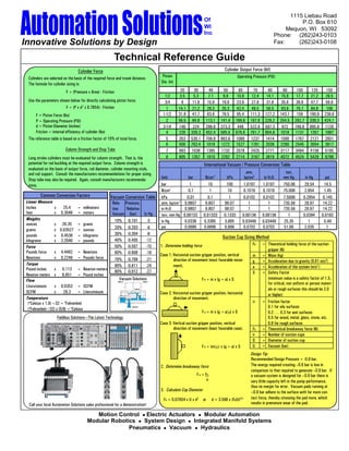
  • 1. 1115 Liebau Road Of P.O. Box 610 WI Mequon, WI 53092 Inc Phone: (262)243-0103 Innovative Solutions by Design Fax: (262)243-0108 Technical Reference Guide Cylinder Force Cylinder Output Force (lbf) Cylinders are selected on the basis of the required force and travel distance. Piston Operating Pressure (PSI) The formula for cylinder sizing is: Dia. (in) F = (Pressure x Area) - Friction 20 30 40 50 60 70 80 90 100 120 150 1/2 3.5 5.3 7.1 8.8 10.6 12.4 14.1 15.9 17.7 21.2 26.5 Use the parameters shown below for directly calculating piston force. 3/4 8 11.9 15.9 19.9 23.9 27.8 31.8 35.8 39.8 47.7 59.6 F = (P x d 2 x 0.7854) - Friction 1 14.1 21.2 28.3 35.3 42.4 49.5 56.5 63.6 70.7 84.8 106 F = Piston Force (lbs) 1-1/2 31.8 47.7 63.6 79.5 95.4 111.3 127.2 143.1 159 190.9 238.6 P = Operating Pressure (PSI) 2 56.5 84.8 113.1 141.4 169.6 197.9 226.2 254.5 282.7 339.3 424.1 d = Piston Diameter (inches) 3-1/4 149 224 298.6 373.3 448 522.6 597.3 672 746.6 895.9 1120 Friction = internal efficiency of cylinder (lbs) 4 226 339.3 452.4 565.5 678.6 791.7 904.8 1018 1131 1357 1697 The reference table is based on a friction factor of 10% of total force. 5 353 530.1 706.9 883.6 1060 1237 1414 1590 1767 2121 2651 6 509 763.4 1018 1272 1527 1781 2036 2290 2545 3054 3817 Column Strength and Stop Tube 7 693 1039 1385 1732 2078 2425 2771 3117 3464 4156 5195 Long stroke cylinders must be evaluated for column strength. That is, the 8 905 1357 1810 2262 2714 3167 3619 4072 4524 5429 6786 potential for rod buckling at the required output force. Column strength is International Vacuum / Pressure Conversion Table evaluated on the basis of output force, rod diameter, cylinder mounting style, and rod support. Consult the manufacturers recommendations for proper sizing. atm, torr, Stop tube may also be required. Again, consult manufacturers recommenda- Unit bar N/cm 2 kPa kp/cm2 in H 2O mm Hg in Hg psi tions. bar 1 10 100 1.0197 1.0197 750.06 29.54 14.5 N/cm2 0.1 1 10 0.1019 0.1019 75.006 2.954 1.45 Common Conversion Factors Vacuum Conversion Table kPa 0.01 0.1 1 0.0102 0.0102 7.5006 0.2954 0.145 Linear Measure Rela- Pressure, atm, kp/cm 2 0.9807 9.807 98.07 1 1 735.56 28.97 14.22 Inches x 25.4 = millmeters tive Relative in H 2O 0.9807 9.807 98.07 1 1 735.56 28.97 14.22 feet x 0.3048 = meters Vacuum (bar) In Hg torr, mm Hg 0.00133 0.01333 0.1333 0.00136 0.00136 1 0.0394 0.0193 Weights 10% -0.101 -3 in Hg 0.0338 0.3385 3.885 0.03446 0.03446 25.35 1 0.49 ounces x 28.35 = grams 20% -0.203 -6 psi 0.0689 0.6896 6.896 0.0703 0.0703 51.68 2.035 1 grams x 0.03527 = ounces pounds x 0.4536 = kilograms 30% -0.304 -9 Suction Cup Sizing Method kilograms x 2.2046 = pounds 40% -0.405 -12 50% -0.507 -15 1. Determine holding force FH = Theoretical holding force of the suction Force Pounds force x 4.4482 = Newtons gripper (N) 60% -0.608 -18 Case 1: Horizontal suction gripper position, vertical Newtons x 0.2248 = Pounds force m = Mass (kg) 70% -0.709 -21 direction of movement (most favorable move- g = Acceleration due to gravity (9.81 m/s2) Torque 80% -0.811 -24 ment). Pound inches x 0.113 = Newton meters a = Acceleration of the system (m/s2 ) 90% -0.912 -27 S = Safety Factor Newton meters x 8.851 = Pound inches Flow Vacuum Solutions F H = m x (g + a) x S (minimum value is a safety factor of 1.5, for critical, non uniform or porous materi- Liters/minute x 0.0353 = SCFM als or rough surfaces this should be 2.0 SCFM x 28.3 = Liters/minute Case 2: Horizontal suction gripper position, horizontal or higher) Temperature direction of movement. (oCelsius x 1.8) +32 = oFahrenheit  = Friction factor  (oFahrenheit—32) x (5/9) = oCelsius  0.1 for oily surfaces F H = m x (g + a/x S )  0.2 . . . 0.3 for wet surfaces Fieldbus Solutions—The Latest Technology  0.5 for wood, metal, glass, stone, etc. Case 3: Vertical suction gripper position, vertical 0.6 for rough surfaces direction of movement (least favorable case). FA = Theoretical breakaway force (N) n = Number of suction cups D = Diameter of suction cup  F H = (m/ x (g + a) x S U = Vacuum (bar) Design Tip: Recommended Design Pressure = -0.6 bar. 2. Determine breakaway force The energy required creating –0.6 bar is low in comparison to that required to generate –0.9 bar. If F A = FH a vacuum system is designed for –0.9 bar there is n very little capacity left in the pump performance, thus no margin for error. Vacuum pads running at 3. Calculate Cup Diameter –0.9 bar adhere to the surface with far more con- FA = 0.07854 x U x d 2 or d = 3.568 x (FA/U) 0.5 tact force, thereby stressing the pad more, which Call your local Automation Solutions sales professional for a demonstration! results in premature wear of the pad. Motion Control  Electric Actuators  Modular Automation Modular Robotics  System Design  Integrated Manifold Systems Pneumatics  Vacuum  Hydraulics
  • 2. Cylinder SCFM Calculation Air Consumption Rate in SCFM Cylinder Cylinder Speed (Inches per Second) Air flow rate requirements (expressed in SCFM or “Standard Cubic Feet per Minute) in pneu- Bore (IN) 3 6 12 18 24 30 36 48 60 matic circuits may be calculated using the following formula: 0.50 0.1 0.3 0.5 0.8 1.1 1.3 1.6 2.1 2.6 Q = 0.0273 d2  L  P + 14.7 0.75 0.3 0.6 1.2 1.8 2.4 3.0 3.6 4.7 5.9 t 14.7 1.00 0.5 1.1 2.1 3.2 4.2 5.3 6.3 8.4 10.5 Q = Rate of air flow in SCFM. 1.50 1.2 2.4 4.7 7.1 9.5 11.9 14.2 19.0 23.7 D = Cylinder piston diameter in inches. 2.00 2.1 4.2 8.4 12.7 16.9 21.1 25.3 33.8 42.2 L = Stroke of cylinder in inches. 3.25 5.6 11.1 22.3 33.4 44.6 55.7 66.9 89.1 111.4 t = Time to complete a stroke in seconds. 4.00 8.4 16.9 33.8 50.6 67.5 84.4 101.3 135.0 168.8 P = Operating pressure in PSIG. 5.00 13.2 26.4 52.7 79.1 105.5 131.9 158.2 211.0 263.7 6.00 19.0 38.0 76.0 113.9 151.9 189.9 227.9 303.8 379.8 Air Valve Selection Guide 7.00 25.8 51.7 103.4 155.1 206.8 258.4 310.1 413.5 516.9 8.00 33.8 67.5 135.0 202.5 270.0 337.6 405.1 540.1 675.1 Air valve flow capacity is expressed in terms of Cv. By using the following tables and formulas you will be able to quickly determine the minimum required air valve capacity Note: Table based on operating pressure of 80 psig. (Cv). Properly sizing your air valve will save you money and space. Example: Solution: The following Cv calculations are based upon standard formulas at standard conditions. Cylinder Bore - 1-1/2” From Table 1 - Area = 1.77 IN2 Those standard conditions are: Cylinder Stroke - 12” From Table 2 - Compression Factor = 7.1  Air at a temperature of 68o F (20o C).  Time to Extend - 2 Seconds - “A” Constant @ 5 PSID = 21.6 Inlet Pressure - 90 PSIG  Absolute downstream or secondary pressure must be 53% of absolute inlet or  Allowable Valve P - 5 PSID primary pressure or greater (P2 x 0.53P1). Below 53%, the air velocity may become sonic and the C v formula does not apply. 1.77  12  7.1 Cylinder Cylinder Compression Cv = —————————— = 0.119 Area  Stroke  Factor 21.8  2  29 (Table 1) (IN) (Table 2) Cv = —————————————————————————— Select a valve that has a Cv of 0.119 or higher. “A” Stroke Constant  Time  29 It is considered good engineering practice to limit the pressure drop P to approximately 10% of (Table 2) (SEC) the primary pressure. An “A” constant of 5 PSID is reasonable for most applications. The smaller the allowable pressure drop, the larger the required valve will become. 1. Effective Areas for NFPA Cylinders Bore Size Cyl Area Bore Size Cyl Area (IN) (IN2) (IN) (IN2) Cylinder Speed 3/4” 0.44 3-1/4” 8.30 1” 0.79 4” 12.57 Cylinder speed is determined by a number of factors. The most important are: 1-1/8” 0.99 5” 19.64 A. Cylinder Dimensions 1-3/8” 1.48 6” 28.27 Load 1-1/2” 1.77 7” 38.48 Mounting Position 2” 3.14 8” 50.27 Cushioning 2-1/2” 4.91 10” 78.54 B. Valves Nominal Flow Rate Response Time 2. Compression Factor and “A” Constants C. Air Supply Tubing Diameter Inlet Compression “A” Constants for various P Tubing Length Pressure Factor 2 PSID 5 PSID 10 PSID 15 PSID Fitting 10 1.7 6.7 Pressure 20 2.4 7.9 11.9 It is important to always consider the system as a whole when determining actuator speeds. Actua- 30 3.0 9.0 13.8 18.2 tor speed is governed by the weakest link in the chain, that is, the component with the lowest flow 40 3.7 9.9 15.4 20.6 23.8 rate. 50 4.4 10.8 16.9 22.8 26.7 Speeds can be increased by: 60 5.1 11.6 18.2 24.8 29.2  quick exhaust valves Using 70 5.8 12.3 19.5 26.7 31.6  with large nominal flow rates (within certain limits) Valves 80 6.4 13.0 20.7 28.4 33.8 90 7.1 13.7 21.8 30.0 35.8  short lines with large cross sections. Using 100 7.8 14.4 22.9 31.6 37.8 Speeds can be reduced by: 110 8.5 15.0 23.9 33.1 39.6  flow control valves. Using 120 9.2 15.6 23.9 34.5 41.4  exhaust air flow controls with flow control silencers Using 130 9.8 16.1 25.8 35.8 43.1  valves with small nominal flow rates. Using 140 10.5 16.7 26.7 37.1 44.7 150 11.2 17.2 27.6 38.4 46.3 Basic Gas Law Flow Rate: SCFM vs. CFM Flow Capacity Cv P 1 V 1 = P2 V 2 SCFM = CFM  Gage Psi + 14.7  Q (SCFM) = 0.978  Cv  (P P 2a)0.5 T1 T2 14.7 SCFM = flow rate in SCFM Where: P = absolute pressure, psia (psig + 14.7) SCFM is compressed air at a specific pressure. Cv = flow capacity of component P = pressure drop across component V = total volume CFM is free air or atmospheric air. T = temperature in 0R, (0 F + 460) P2a = final downstream pressure (P 1a — P) Automation Solutions of WI, Inc. Page 2 Innovative Solutions by Design
  • 3. SCFM Through an Air Valve Flow Rate Reference Table Quick Guideline for Sizing Valves to Cylinders SCFM through an air valve can be calculated when the Cv is known by using the following CV SCFM Qn (l/min) Flow Rate formula: 0.010 0.36 10 Cylinder Piston Dia. Valve Cv / SCFM 0.050 1.79 50 (in / mm) Port Size (Up to) Q = Cv  A where “A” is the constant for various pressure drops from Table 2. 0.075 2.69 75 Up to 1/2” / 12 mm M3 0.08 / 2.8 Please note that it is important to determine the pressure drop across the valve. Of course, 0.100 3.58 100 1/2” to 1” / 12 to 25 mm M5 0.20 / 7.1 it is also possible to solve for valve Cv when the SCFM and “A” constant (from Table 2) are 0.125 4.48 125 1” to 2” / 25 to 50 mm (G) 1/8 0.50 / 17.7 known. 0.150 5.37 150 2” to 4” / 50 to 100 mm (G) 1/4 1.14 / 40.2 0.200 7.16 200 6” to 8” / 150 to 200 mm (G) 1/2 3.00 / 105.9 Air Flow Rate through Conductors 0.300 10.74 300 8” to 12” / 200 to 320 mm (G) 3/4, 1 6.00 / 211.8 0.400 14.32 400 The formula for calculating the C v of a conductor is: 0.500 17.90 500 The figures in the table above provide approximate Cv = 42.3  a  d .5 0.750 26.85 750 values, which can be used as a guideline, for determin- f  L 1.000 35.80 1000 ing the valve size needed for cylinders of various piston 1.500 53.70 1500 diameters. The guidelines indicate valve sizes which Where: 2.000 71.60 2000 should be sufficient for attaining cylinder speeds Cv = flow capability of length of conductor 2.500 89.50 2500 encountered in most typical applications. a = internal area of the conductor, in2 3.000 107.40 3000 d = conductor diameter, in. 3.500 125.30 3500 ISO Valve Port Designations f = coefficient of friction of the interior conductor surface 4.000 143.20 4000 L = conductor length (real or equivalent), in. Working Ports 2, 4 5.000 179.00 5000 Supply Port 1 Note: “Real” conductor length is the actual conductor length. “Equivalent” refers to the 6.000 214.80 6000 Exhaust Ports 3, 5 additional length that fittings “add” to the actual conductor length. Elbows, tubing bends 7.000 250.60 7000 Pilot Ports 10, 12, 14 all add additional resistance or “additional” length that need to be considered in the plan- 8.000 286.40 8000 Pilot Exhaust Ports 82, 84 ning of a system. 9.000 322.20 9000 10.000 358.00 10000 Description Typical ISO Valve Symbols Flow Coefficient Cv for Pneumatic Conductors 2 / 2, Normally Closed 2 Conductor Length in Feet Sgl Solenoid, Spring Return 12 Direct Solenoid Operated 1 Conductor Size Material ID Area f 1 2 3 5 10 20 30 1/8" NPT Pipe 0.269 0.0568 0.0365 1.88 1.33 1.09 0.84 0.60 0.42 0.34 2 / 2, Normally Open 2 1/4" NPT Pipe 0.365 0.1046 0.0333 4.23 2.99 2.44 1.89 1.34 0.95 0.77 Sgl Solenoid, Spring Return 12 Direct Solenoid Operated 1 3/8" NPT Pipe 0.493 0.1909 0.0305 9.37 6.63 5.41 4.19 2.96 2.10 1.71 1/2" NPT Pipe 0.622 0.3039 0.0285 17.33 12.26 10.01 7.75 5.48 3.88 3.16 3 / 2, Normally Closed 2 Sgl Solenoid, Spring Return 12 3/4" NPT Pipe 0.824 0.5333 0.0265 36.31 25.68 20.96 16.24 11.48 8.12 6.63 Solenoid Pilot Operated 3 1 1" NPT Pipe 1.049 0.8643 0.0248 68.64 48.53 39.63 30.70 21.70 15.35 12.53 1-1/4" NPT Pipe 1.380 1.4957 0.0232 140.86 99.60 81.33 63.00 44.54 31.50 25.72 3 / 2, Normally Open 2 1-1/2" NPT Pipe 1.610 2.0358 0.0223 211.23 149.36 121.95 94.46 66.80 47.23 38.56 Sgl Solenoid, Spring Return 12 Solenoid Pilot Operated 3 1 2" NPT Pipe 2.067 3.3556 0.0211 405.56 286.77 234.15 181.37 128.25 90.69 74.04 1/8" Polyurethane Tube 0.063 0.0031 0.0342 0.05 0.04 0.03 0.02 0.02 0.01 0.01 5 / 2, 4 Way Valve 2 4 Sgl Solenoid, Spring Return 12 14 5/32" Polyurethane Tube 0.094 0.0069 0.0322 0.14 0.10 0.08 0.06 0.05 0.03 0.03 Solenoid Pilot Operated 3 1 5 3/16" Polyurethane Tube 0.125 0.0123 0.0305 0.30 0.21 0.18 0.14 0.10 0.07 0.06 1/4" Polyurethane Tube 0.156 0.0192 0.0290 0.54 0.38 0.31 0.24 0.17 0.12 0.10 5 / 2, 4 Way Valve 2 4 Double Solenoid 12 14 5/16" Polyurethane Tube 0.188 0.0276 0.0282 0.87 0.61 0.50 0.39 0.27 0.19 0.16 Solenoid Pilot Operated 3 1 5 3/8" Polyurethane Tube 0.250 0.0491 0.0260 1.86 1.31 1.07 0.83 0.59 0.42 0.34 1/2" Polyurethane Tube 0.328 0.0846 0.0243 3.79 2.68 2.19 1.70 1.20 0.85 0.69 5 / 3, Closed Center 2 4 Dbl Solenoid, Spring Centered 12 14 1/2" PQ-PA Air Pipe 0.354 0.0984 0.0226 4.76 3.36 2.75 2.13 1.50 1.06 0.87 Solenoid Pilot Operated 3 1 5 5/8" PQ-PA Air Pipe 0.472 0.1750 0.0213 10.06 7.11 5.81 4.50 3.18 2.25 1.84 3/4" PQ-PA Air Pipe 0.551 0.2384 0.0206 15.06 10.65 8.69 6.73 4.76 3.37 2.75 5 / 3, Exhaust Center 2 4 Dbl Solenoid, Spring Centered 12 14 7/8" PQ-PA Air Pipe 0.709 0.3948 0.0199 28.78 20.35 16.61 12.87 9.10 6.43 5.25 Solenoid Pilot Operated 3 15 1/2" PQ-AL Air Pipe 0.394 0.1219 0.0226 6.22 4.40 3.59 2.78 1.97 1.39 1.13 5/8" PQ-AL Air Pipe 0.512 0.2059 0.0213 12.33 8.72 7.12 5.51 3.90 2.76 2.25 5 / 3, Pressure Center 2 4 12 14 3/4" PQ-AL Air Pipe 0.630 0.3117 0.0206 21.05 14.88 12.15 9.41 6.66 4.71 3.84 Dbl Solenoid, Spring Centered Solenoid Pilot Operated 3 15 7/8" PQ-AL Air Pipe 0.787 0.4865 0.0199 37.36 26.41 21.57 16.71 11.81 8.35 6.82 System Cvs Every component in a pneumatic system is important to its overall performance. Each component; filter, regulator, lubricator, air valve, and transmission line (fittings, tubing, pipe, etc.) creates a resistance to flow. It is important to realize each component in “series” creates a pressure drop. If the total pressure drop through all the components is excessive, insufficient pressure wil l be available to move the load at its required speed. The schematic to the left illustrates this point. Each component can be evaluated for its flow capability and assigned a C v factor (flow coefficient). As air flows through each component, filter, then regulator, then lubricator, etc. it provides resistance to flow C v =4.5 C v=4.0 Cv =5.0 C v=5.0 Cv =5.0 which creates a pressure drop. Note how the “system” C v or Cvs becomes lower as each component is evaluated on a system C v=2.99 level. Cv =4.5 Just as electrical resistance or conductance can be measured on a system level, so can “pneumatic conductance”. The formula Cv =2.57 Cv =2.28 for calculating system Cvs is: Cv =2.03 1 C v =1.89 Cvs = ((1/C v1)2 + (1/C v2)2 + (1/C v3)2 + (1/C v4)2 + (1/Cv5)2 + . . . . . + (1/Cvi )2 ) 0.5 Automation Solutions of WI, Inc. Page 3 Innovative Solutions by Design
  • 4. How Clean Must Compressed Air Be? Classification of Product Categories Compressed air must always be clean enough so that it causes no malfunction or damage to Solids Water Dew Point Max. Oil Content components. The quality of compressed air is identified by quality classes set forth in ISO Application Class (micron) Class (0F / 0C) Class (ppm / mg/m3) 8573-1. The table below establishes which contaminants are allowable in the corresponding Mining 5 40 7 -- 5 20.75/ 25 compressed air quality classes. Laundry 5 40 6 50 / 0 4 4.15 / 5 The wide range of applications for compressed air imposes variable demands for air quality. Welding Equipment 5 40 6 50 / 10 5 20.75 / 25 If a high quality of compressed air is required, more steps of filtration must be used. Machine Tools 5 40 4 37 / 3 5 20.75 / 25 Compressed Air Cylinders 5 40 4 37 / 3 5 20.75 / 25 Compressed Air Filtration Quality Classes per DIN 8573-1 Compressed Air Valves 3 to 5 5 to 40 4 37 / 3 5 20.75 / 25 1. Particle Size 2. Water Content 3. Oil Content Class Max. Particle Size Max. Particulate Density Max. Dew Point Max. Oil Concentration Packaging 5 40 4 37 / 3 3 0.83 / 1 (micron) (ppm / mg/m3 ) (û F / ûC) (ppm / mg/m3) Precision Air Regulator 3 5 4 37 / 3 3 0.83 / 1 1 0.1 0.08 / 0.1 -94 / -70 0.01 / 0.01 Air Measurement 2 1 4 37 / 3 3 0.83 / 1 2 1 0.83 / 1 -40 / -40 0.08 / 0.1 Warehouse Ventilation 2 1 3 -4 / -20 3 0.83 / 1 3 5 4.15 / 5 -4 / -20 0.83 / 1 Sensors 2 1 2 to 3 -40 to -4 / 2 0.08 / 0.1 4 15 6.64 / 8 37 / 3 4.15 / 5 -40 to -20 5 40 8.30 / 10 45 / 7 20.75 / 25 Food Processing 2 1 4 37 / 3 1 0.01 / 0.01 6 – – 50 / 10 – Photo Processing 1 0.01 to 0.1 2 -40 / -40 1 0.01 / 0.01 IP / NEMA Classifications of Protection IP Classifications NEMA / UL Classifications Ingress protection class of enclosures is according to IEC 529 given in form of IP The National Electrical Manufacturers Association is a U.S. Manufacturers organization. NEMA performance classification, a two digit coding which is shown below. criteria and test methods are used by Underwriters’ Laboratories as guidelines for investigation and listing of electrical enclosures. First Number Second Number Approximate IP equivalents are in parenthesis. Protection against solid objects Protection against liquids IP Description IP Description NEMA Description 0 No protection 0 No protection 1 Indoor use primarily to provide a degree of protection against contact with the enclosed equipment and guard against a limited amount of falling dirt. (IP30) 1 Protected against solid object up to 50 1 Protected against vertically falling 2 Indoor use to provide a degree of protection against limited amounts of falling water and direct. (IP31) mm eg accidental touch by hands. drops of water. 2 Protected against solid objects up to 2 Protected against direct sprays of 3 Outdoor use to provide a degree of protection against windblown dust, rain and sleet; undamaged by 12 mm eg fingers. water up to 150 from the vertical. the formation of ice on the enclosure. (IP64) 3 Protected against solid object up to 3 Protected against direct sprays of 3R Outdoor use to provide a degree of protection against rain and sleet; undamaged by the formation of 2.5 mm eg (tools + small wires). water up to 600 from the vertical. ice on the enclosure. (IP32) Protected against solid object up to Protected against water sprayed Outdoor use to provide a degree of protection against windblown dust, rain and sleet; external mecha- 4 1.0 mm eg (tools + small wires). 4 from all directions—limited ingress 3S nisms remain operable while ice laden. permitted. Protected against dust—limited ingress Protected against low pressure jets Indoor or outdoor use to provide a degree of protection against splashing water, windblown dust and 5 permitted (no harmful deposit). 5 of water from all directions—limited 4 rain, hose directed water; undamaged by the formation of ice on the enclosure. (IP66) ingress permitted. Protected against strong jets of Indoor or outdoor use to provide a degree of protection against splashing water, windblown dust and 6 Totally protected against dust. 6 water eg for use on ship decks— 4X rain, hose directed water; undamaged by the formation of ice on the enclosure. Resists corrosion. limited ingress permitted. (IP66) 7 Protected against the affects of 6 Indoor or outdoor use to provide a degree of protection against the entry of water during temporary immersion between 15 cm and 1 m. submersion at a limited depth; undamaged by the formation of ice on the enclosure. 8 Protected against long periods of 6P Indoor or outdoor use to provide a degree of protection against the entry of water during prolonged submersion at a limited depth. immersion under pressure. 11 Indoor use to provide by oil immersion a degree of protection of the enclosed equipment against the corrosive effects of corrosive liquids and gases. 12/12K Indoor use to provide a degree of protection against dust, falling dirt and dripping noncorrosive cool- ants. (IP65) 13 Indoor use to provide a degree of protection against dust, and spraying of water oil and noncorrosive coolants. (IP65) Variations of Ohms Law Electrical Terms Sensor Glossary Volt: The unit of measure for electrical potential. Analog Output: Output current or voltage of a device which varies in direct proportion E Watt: The unit of measure for electrical power. to the input. WR W R W I Ohms: Measure of resistance to the flow of current. Digital Output: An output which changes value by a discrete increment in response to R E I W Current: The flow of electrons from negative to positive. an incremental change in the input signal. If a device has only two unique values for IR (VOLTS) (AMP) the output, such as ON and OFF, the digital output may also be called a binary output. E Current Surge: This is a short term (transient) condition E (OHMS) (WATTS) causing a larger than normal amount of current to flow NPN Output: An output from a switch device which connects the negative potential EI I R W through a conductor. to the load when the device is actuated. NPN outputs are negative switching (sinking). W I2 R Voltage Spike: This is a short term (transient) condition PNP Output: An output from a switch device which connects the positive potential to I2 E2 E2 causing a larger than normal amount of voltage to be applied the load when the device is actuated. PNP outputs are positive switching (sourcing). W R to a circuit. Voltage spikes can often cause damage to an electric device that is not properly protected. Automation Solutions of WI, Inc. Page 4 Innovative Solutions by Design