SlideShare una empresa de Scribd logo
1 de 19
Frequency Modulation and 
Application 
Submitted by: 
Darshil Shah 
(IU1241090051)
Content 
1. Flow diagram 
2. What is frequency modulation? 
3. Frequency modulation index 
4. Significant-sidebands Spectrum 
5. Types of FM 
6. Generation of FM using PM 
7. Advantages and disadvantages 
8. Comparison with FM and PM 
9. Applications
Modulation 
Pulse Wave 
Modulation 
Amplitude 
Modulation 
Continuous Wave 
Modulation 
Linear Modulation 
Non-Linear 
Modulation 
Frequency 
Modulation 
Phase Modulation
What is frequency modulation? 
When the frequency of carrier wave is changed in 
accordance with the message signal, The process is called 
frequency modulation. 
In FM the carrier amplitude remain constant the carrier 
frequency varies 
It is a type of Angle modulation 
Why Frequency modulation is called nonlinear-modulation?
FM modulation index 
• FM modulation index is equal to the ratio of the 
frequency deviation to the modulating frequency. 
• Thus the formula for the modulation index for FM 
is simply given by that shown below: 
Frequency Deviation 
Modulating Frequency 
And also,
Significant Sidebands – Spectrum 
• The table below shows the number of significant 
sidebands for various modulation 
 No of sidebands  1% of 
unmodulated carrier 
Bandwidth 
0.1 2 2fm 
0.3 4 4fm 
0.5 4 4fm 
1.0 6 6fm 
2.0 8 8fm 
5.0 16 16fm 
10.0 28 28fm 
Example: 
For  = 5, 
16 sidebands 
(8 pairs).
Types of FM 
Narrow band FM 
1. Narrow band FM is defined as the situation where the 
modulation index  is small. 
2. From the table of Bessel functions it may be seen that for 
small , (  0.3) there is only the carrier and significant 
sidebands, i.e. BW = 2fm. 
FM with   0.3 is referred to as narrowband FM (NBFM). 
3. Maximum modulating frequency is usually 3kHz 
4. maximum frequency deviation is =75 kHz.
Types of FM 
Wide band FM 
1. Wideband FM is defined as the situation where the 
modulation index  is larger. 
2. For  > 0.3 there are more than 2 significant sidebands. As  
increases the number of sidebands increases. This is referred 
to as wideband FM (WBFM). 
3. Modulation frequencies extend from 30 Hz to 15 kHz. 
4. Maximum permissible deviation is=75 kHz. 
5. Wideband FM system need large bandwidth, typically 15 times 
that of narrowband FM system.
Generation of FM using PM 
Modulating Wave x(t) FM Wave 
Integrator 
Phase 
Modulator 
Carrier 
Oscillator 
dtt x ) (  
Eccos(2fct)
Advantages 
1. Amplitude of the frequency modulated wave remains 
unaffected. 
2. Large decrease in noise, hence increase in S/N ratio. 
3. Noise may reduce by increasing deviation. 
4. Frequency allocation allows for a guard band which 
reduces adjacent channel interference. 
5. Operate In Very high frequency (VHF).
Disadvantages 
• FM has too much advantages besides it also has some 
disadvantages 
1. FM wave can’t cover large area. 
2. Transmitting & receiving equipments for FM are 
complex & costly. 
3. A much wider channel, typically 200 kHz, is needed for 
FM.
Comparison of FM with PM 
Sr. 
No. 
FM PM 
1 Frequency deviation is proportional to 
modulating voltage 
Phase deviation is proportional 
to the modulating voltage 
2 Noise immunity is better than AM and PM Noise immunity is better than 
AM but worse than FM 
3 SNR is better than PM SNR is worse than FM 
4 FM is widely used for radio broadcasting PM is only used in some mobile 
systems 
5 It is possible to receive FM on PM receive It is possible to receive PM on 
FM receive 
6 Modulation index is proportional to 
modulating voltage as well as the modulating 
frequency . 
Modulation index is 
proportional to modulating 
voltage
Comparison of FM and AM 
Sr. 
No. 
FM AM 
1 FM receivers are immune to noise AM receivers are not immune 
to noise 
2 It is possible to decrease noise by increasing 
deviation 
This feature is absent in AM 
3 Bandwidth is higher and depends on modulation 
index 
Bandwidth is lower 
compared to AM but 
independent of modulation 
index 
4 FM transmission and reception equipment are more 
complex 
FM transmission and 
reception equipment are less 
complex 
5 All transmitted power is useful Carrier power and one 
sideband power is useless
FM Radio 
FM radio uses a modulation index, m > 1, and this is called wideband FM. As its name 
suggests the bandwidth is much larger than AM. 
In national radio broadcasts using FM, the frequency deviation of the carrier  fc , is 
chosen to be 75kHz, and the information baseband is the high fidelity range 20Hz to 
15kHz. 
BW of FM radio=2(75k+15k) 
=180khz 
Applications:
Television Sound: 
In terrestrial TV broadcasts, the video information is transmitted using AM . 
However the sound information is transmitted using FM, in order to reduce possible 
interference between the video and sound signals. In this case, the maximum deviation of 
the carrier,  fc , is chosen to be 50kHz, and the information baseband is again the high 
fidelity range 20Hz to 15kHz. Therefore the bandwidth required for TV Sound is: 
BW Of TV Sound=2(50k+15k) 
=130khz 
Satellite TV. 
Some satellite TV transmissions broadcast an analogue video signal using FM. This 
helps to obtain an acceptable signal at the receiving station In this case, the maximum deviation 
of the carrier  fc , is chosen to be about 10 MHz, with a video baseband of around 5MHz. 
Therefore the bandwidth required for Satellite TV is: 
BW of satellite TV =2(10+5) 
=30Mhz
References 
• http://www.silabs.com/Marcom%20Documents/Resources/FMTutorial.pdf 
• http://en.wikibooks.org/wiki/Communication_Systems/Frequency_Modulati 
on 
• http://www.radio-electronics.com/info/rf-technology-design/fm-frequency-modulation/ 
spectrum-bandwidth-sidebands.php 
• http://searchnetworking.techtarget.com/definition/frequency-modulation 
• https://www.youtube.com/watch?v=SmW4z76KgNQ 
• https://www.standrews.ac.uk/~www_pa/Scots_Guide/RadCom/part12/page 
1.html 
• Analog and digital communication system by Sanjay Sharma. 
• Modern digital and analog communication systems by B.P. Lathi
Frequency modulation and its application

Más contenido relacionado

La actualidad más candente

La actualidad más candente (20)

Analog modulation
Analog modulationAnalog modulation
Analog modulation
 
Pulse modulation
Pulse modulationPulse modulation
Pulse modulation
 
Amplitude modulation & demodulation
Amplitude modulation & demodulation Amplitude modulation & demodulation
Amplitude modulation & demodulation
 
Pulse modulation
Pulse modulationPulse modulation
Pulse modulation
 
Fm transmitter and receivers
Fm transmitter and receiversFm transmitter and receivers
Fm transmitter and receivers
 
Amplitude Modulation ppt
Amplitude Modulation pptAmplitude Modulation ppt
Amplitude Modulation ppt
 
transmission-line-and-waveguide-ppt
transmission-line-and-waveguide-ppttransmission-line-and-waveguide-ppt
transmission-line-and-waveguide-ppt
 
Frequency-Shift Keying
Frequency-Shift KeyingFrequency-Shift Keying
Frequency-Shift Keying
 
Linear modulation
Linear modulation Linear modulation
Linear modulation
 
Chap 5 (small scale fading)
Chap 5 (small scale fading)Chap 5 (small scale fading)
Chap 5 (small scale fading)
 
Lecture6 modulation
Lecture6 modulationLecture6 modulation
Lecture6 modulation
 
QUADRATURE AMPLITUDE MODULATION
QUADRATURE AMPLITUDE MODULATIONQUADRATURE AMPLITUDE MODULATION
QUADRATURE AMPLITUDE MODULATION
 
Chapter 4
Chapter 4Chapter 4
Chapter 4
 
Dsss final
Dsss finalDsss final
Dsss final
 
Digital modulation technique
Digital modulation techniqueDigital modulation technique
Digital modulation technique
 
ASk,FSK,PSK
ASk,FSK,PSKASk,FSK,PSK
ASk,FSK,PSK
 
Pulse code modulation
Pulse code modulationPulse code modulation
Pulse code modulation
 
Rf fundamentals
Rf fundamentalsRf fundamentals
Rf fundamentals
 
Chapter 5 fm receivers
Chapter 5  fm receiversChapter 5  fm receivers
Chapter 5 fm receivers
 
AM RadioReceiver
AM RadioReceiverAM RadioReceiver
AM RadioReceiver
 

Similar a Frequency modulation and its application

Frequency modulation and demodulation along with types
Frequency modulation and demodulation along with typesFrequency modulation and demodulation along with types
Frequency modulation and demodulation along with typesswatihalunde
 
ADC-UNITT-2.pptx
ADC-UNITT-2.pptxADC-UNITT-2.pptx
ADC-UNITT-2.pptxLALITHAS47
 
Frequency and phase modulation
Frequency and phase modulationFrequency and phase modulation
Frequency and phase modulationasdfghjkl13496
 
Fm Transmitter and receiver
 Fm Transmitter and receiver Fm Transmitter and receiver
Fm Transmitter and receivernurnaser1234
 
4 3-3 frequency-modulation
4 3-3 frequency-modulation4 3-3 frequency-modulation
4 3-3 frequency-modulationlcborja57
 
13 Transmission_bandwidth_of_FM_signals.pdf
13 Transmission_bandwidth_of_FM_signals.pdf13 Transmission_bandwidth_of_FM_signals.pdf
13 Transmission_bandwidth_of_FM_signals.pdfMohamedshabana38
 
Different type of modulation schemes used in Analog Modulation
Different type of modulation schemes used in Analog ModulationDifferent type of modulation schemes used in Analog Modulation
Different type of modulation schemes used in Analog Modulation04720VivekaS
 
advantages modulation_PRP.pptx
advantages modulation_PRP.pptxadvantages modulation_PRP.pptx
advantages modulation_PRP.pptxPravinPrajapati53
 
Introduction to communication system lecture3
Introduction to communication system lecture3Introduction to communication system lecture3
Introduction to communication system lecture3Jumaan Ally Mohamed
 
comparisonofamandfmmodulation-200811174120 (1).pptx
comparisonofamandfmmodulation-200811174120 (1).pptxcomparisonofamandfmmodulation-200811174120 (1).pptx
comparisonofamandfmmodulation-200811174120 (1).pptxfilembarketema
 
Communication system 1 chapter 3 - part 1
Communication system 1 chapter 3 - part 1Communication system 1 chapter 3 - part 1
Communication system 1 chapter 3 - part 1BetelihemMesfin1
 

Similar a Frequency modulation and its application (20)

Frequency modulation and demodulation along with types
Frequency modulation and demodulation along with typesFrequency modulation and demodulation along with types
Frequency modulation and demodulation along with types
 
Fm
FmFm
Fm
 
Frequency modulation2
Frequency modulation2Frequency modulation2
Frequency modulation2
 
ADC-UNITT-2.pptx
ADC-UNITT-2.pptxADC-UNITT-2.pptx
ADC-UNITT-2.pptx
 
Frequency and phase modulation
Frequency and phase modulationFrequency and phase modulation
Frequency and phase modulation
 
Fm Transmitter and receiver
 Fm Transmitter and receiver Fm Transmitter and receiver
Fm Transmitter and receiver
 
EC6651 COMMUNICATION ENGINEERING UNIT 1
EC6651 COMMUNICATION ENGINEERING UNIT 1EC6651 COMMUNICATION ENGINEERING UNIT 1
EC6651 COMMUNICATION ENGINEERING UNIT 1
 
4 3-3 frequency-modulation
4 3-3 frequency-modulation4 3-3 frequency-modulation
4 3-3 frequency-modulation
 
Frequency modulation
Frequency modulationFrequency modulation
Frequency modulation
 
13 Transmission_bandwidth_of_FM_signals.pdf
13 Transmission_bandwidth_of_FM_signals.pdf13 Transmission_bandwidth_of_FM_signals.pdf
13 Transmission_bandwidth_of_FM_signals.pdf
 
Different type of modulation schemes used in Analog Modulation
Different type of modulation schemes used in Analog ModulationDifferent type of modulation schemes used in Analog Modulation
Different type of modulation schemes used in Analog Modulation
 
FM-PM.ppt
FM-PM.pptFM-PM.ppt
FM-PM.ppt
 
advantages modulation_PRP.pptx
advantages modulation_PRP.pptxadvantages modulation_PRP.pptx
advantages modulation_PRP.pptx
 
Introduction to communication system lecture3
Introduction to communication system lecture3Introduction to communication system lecture3
Introduction to communication system lecture3
 
Frequency deviation
Frequency deviation Frequency deviation
Frequency deviation
 
comparisonofamandfmmodulation-200811174120 (1).pptx
comparisonofamandfmmodulation-200811174120 (1).pptxcomparisonofamandfmmodulation-200811174120 (1).pptx
comparisonofamandfmmodulation-200811174120 (1).pptx
 
Frequency modulation
Frequency modulationFrequency modulation
Frequency modulation
 
Communication system 1 chapter 3 - part 1
Communication system 1 chapter 3 - part 1Communication system 1 chapter 3 - part 1
Communication system 1 chapter 3 - part 1
 
Lec am modulation
Lec am modulationLec am modulation
Lec am modulation
 
Chapter03 fm modulation
Chapter03 fm modulationChapter03 fm modulation
Chapter03 fm modulation
 

Más de Darshil Shah

final report_51_33_17
final report_51_33_17final report_51_33_17
final report_51_33_17Darshil Shah
 
Final project report on Solar street light
Final project report on Solar street light Final project report on Solar street light
Final project report on Solar street light Darshil Shah
 
Charge coupled device(ccd)
Charge coupled device(ccd)Charge coupled device(ccd)
Charge coupled device(ccd)Darshil Shah
 
Photoelectric sensors
Photoelectric sensorsPhotoelectric sensors
Photoelectric sensorsDarshil Shah
 

Más de Darshil Shah (8)

Umc_18_CMOS
Umc_18_CMOSUmc_18_CMOS
Umc_18_CMOS
 
Task i
Task iTask i
Task i
 
final report_51_33_17
final report_51_33_17final report_51_33_17
final report_51_33_17
 
Final project report on Solar street light
Final project report on Solar street light Final project report on Solar street light
Final project report on Solar street light
 
Telemedicine
TelemedicineTelemedicine
Telemedicine
 
Pn sequence
Pn sequencePn sequence
Pn sequence
 
Charge coupled device(ccd)
Charge coupled device(ccd)Charge coupled device(ccd)
Charge coupled device(ccd)
 
Photoelectric sensors
Photoelectric sensorsPhotoelectric sensors
Photoelectric sensors
 

Último

signals in triangulation .. ...Surveying
signals in triangulation .. ...Surveyingsignals in triangulation .. ...Surveying
signals in triangulation .. ...Surveyingsapna80328
 
Paper Tube : Shigeru Ban projects and Case Study of Cardboard Cathedral .pdf
Paper Tube : Shigeru Ban projects and Case Study of Cardboard Cathedral .pdfPaper Tube : Shigeru Ban projects and Case Study of Cardboard Cathedral .pdf
Paper Tube : Shigeru Ban projects and Case Study of Cardboard Cathedral .pdfNainaShrivastava14
 
Earthing details of Electrical Substation
Earthing details of Electrical SubstationEarthing details of Electrical Substation
Earthing details of Electrical Substationstephanwindworld
 
Levelling - Rise and fall - Height of instrument method
Levelling - Rise and fall - Height of instrument methodLevelling - Rise and fall - Height of instrument method
Levelling - Rise and fall - Height of instrument methodManicka Mamallan Andavar
 
ROBOETHICS-CCS345 ETHICS AND ARTIFICIAL INTELLIGENCE.ppt
ROBOETHICS-CCS345 ETHICS AND ARTIFICIAL INTELLIGENCE.pptROBOETHICS-CCS345 ETHICS AND ARTIFICIAL INTELLIGENCE.ppt
ROBOETHICS-CCS345 ETHICS AND ARTIFICIAL INTELLIGENCE.pptJohnWilliam111370
 
Prach: A Feature-Rich Platform Empowering the Autism Community
Prach: A Feature-Rich Platform Empowering the Autism CommunityPrach: A Feature-Rich Platform Empowering the Autism Community
Prach: A Feature-Rich Platform Empowering the Autism Communityprachaibot
 
Research Methodology for Engineering pdf
Research Methodology for Engineering pdfResearch Methodology for Engineering pdf
Research Methodology for Engineering pdfCaalaaAbdulkerim
 
Gravity concentration_MI20612MI_________
Gravity concentration_MI20612MI_________Gravity concentration_MI20612MI_________
Gravity concentration_MI20612MI_________Romil Mishra
 
TEST CASE GENERATION GENERATION BLOCK BOX APPROACH
TEST CASE GENERATION GENERATION BLOCK BOX APPROACHTEST CASE GENERATION GENERATION BLOCK BOX APPROACH
TEST CASE GENERATION GENERATION BLOCK BOX APPROACHSneha Padhiar
 
Python Programming for basic beginners.pptx
Python Programming for basic beginners.pptxPython Programming for basic beginners.pptx
Python Programming for basic beginners.pptxmohitesoham12
 
Engineering Drawing section of solid
Engineering Drawing     section of solidEngineering Drawing     section of solid
Engineering Drawing section of solidnamansinghjarodiya
 
SOFTWARE ESTIMATION COCOMO AND FP CALCULATION
SOFTWARE ESTIMATION COCOMO AND FP CALCULATIONSOFTWARE ESTIMATION COCOMO AND FP CALCULATION
SOFTWARE ESTIMATION COCOMO AND FP CALCULATIONSneha Padhiar
 
THE SENDAI FRAMEWORK FOR DISASTER RISK REDUCTION
THE SENDAI FRAMEWORK FOR DISASTER RISK REDUCTIONTHE SENDAI FRAMEWORK FOR DISASTER RISK REDUCTION
THE SENDAI FRAMEWORK FOR DISASTER RISK REDUCTIONjhunlian
 
Artificial Intelligence in Power System overview
Artificial Intelligence in Power System overviewArtificial Intelligence in Power System overview
Artificial Intelligence in Power System overviewsandhya757531
 
Comprehensive energy systems.pdf Comprehensive energy systems.pdf
Comprehensive energy systems.pdf Comprehensive energy systems.pdfComprehensive energy systems.pdf Comprehensive energy systems.pdf
Comprehensive energy systems.pdf Comprehensive energy systems.pdfalene1
 
List of Accredited Concrete Batching Plant.pdf
List of Accredited Concrete Batching Plant.pdfList of Accredited Concrete Batching Plant.pdf
List of Accredited Concrete Batching Plant.pdfisabel213075
 
Module-1-(Building Acoustics) Noise Control (Unit-3). pdf
Module-1-(Building Acoustics) Noise Control (Unit-3). pdfModule-1-(Building Acoustics) Noise Control (Unit-3). pdf
Module-1-(Building Acoustics) Noise Control (Unit-3). pdfManish Kumar
 
OOP concepts -in-Python programming language
OOP concepts -in-Python programming languageOOP concepts -in-Python programming language
OOP concepts -in-Python programming languageSmritiSharma901052
 
『澳洲文凭』买麦考瑞大学毕业证书成绩单办理澳洲Macquarie文凭学位证书
『澳洲文凭』买麦考瑞大学毕业证书成绩单办理澳洲Macquarie文凭学位证书『澳洲文凭』买麦考瑞大学毕业证书成绩单办理澳洲Macquarie文凭学位证书
『澳洲文凭』买麦考瑞大学毕业证书成绩单办理澳洲Macquarie文凭学位证书rnrncn29
 

Último (20)

signals in triangulation .. ...Surveying
signals in triangulation .. ...Surveyingsignals in triangulation .. ...Surveying
signals in triangulation .. ...Surveying
 
Paper Tube : Shigeru Ban projects and Case Study of Cardboard Cathedral .pdf
Paper Tube : Shigeru Ban projects and Case Study of Cardboard Cathedral .pdfPaper Tube : Shigeru Ban projects and Case Study of Cardboard Cathedral .pdf
Paper Tube : Shigeru Ban projects and Case Study of Cardboard Cathedral .pdf
 
Earthing details of Electrical Substation
Earthing details of Electrical SubstationEarthing details of Electrical Substation
Earthing details of Electrical Substation
 
Levelling - Rise and fall - Height of instrument method
Levelling - Rise and fall - Height of instrument methodLevelling - Rise and fall - Height of instrument method
Levelling - Rise and fall - Height of instrument method
 
ROBOETHICS-CCS345 ETHICS AND ARTIFICIAL INTELLIGENCE.ppt
ROBOETHICS-CCS345 ETHICS AND ARTIFICIAL INTELLIGENCE.pptROBOETHICS-CCS345 ETHICS AND ARTIFICIAL INTELLIGENCE.ppt
ROBOETHICS-CCS345 ETHICS AND ARTIFICIAL INTELLIGENCE.ppt
 
Prach: A Feature-Rich Platform Empowering the Autism Community
Prach: A Feature-Rich Platform Empowering the Autism CommunityPrach: A Feature-Rich Platform Empowering the Autism Community
Prach: A Feature-Rich Platform Empowering the Autism Community
 
Research Methodology for Engineering pdf
Research Methodology for Engineering pdfResearch Methodology for Engineering pdf
Research Methodology for Engineering pdf
 
Gravity concentration_MI20612MI_________
Gravity concentration_MI20612MI_________Gravity concentration_MI20612MI_________
Gravity concentration_MI20612MI_________
 
Designing pile caps according to ACI 318-19.pptx
Designing pile caps according to ACI 318-19.pptxDesigning pile caps according to ACI 318-19.pptx
Designing pile caps according to ACI 318-19.pptx
 
TEST CASE GENERATION GENERATION BLOCK BOX APPROACH
TEST CASE GENERATION GENERATION BLOCK BOX APPROACHTEST CASE GENERATION GENERATION BLOCK BOX APPROACH
TEST CASE GENERATION GENERATION BLOCK BOX APPROACH
 
Python Programming for basic beginners.pptx
Python Programming for basic beginners.pptxPython Programming for basic beginners.pptx
Python Programming for basic beginners.pptx
 
Engineering Drawing section of solid
Engineering Drawing     section of solidEngineering Drawing     section of solid
Engineering Drawing section of solid
 
SOFTWARE ESTIMATION COCOMO AND FP CALCULATION
SOFTWARE ESTIMATION COCOMO AND FP CALCULATIONSOFTWARE ESTIMATION COCOMO AND FP CALCULATION
SOFTWARE ESTIMATION COCOMO AND FP CALCULATION
 
THE SENDAI FRAMEWORK FOR DISASTER RISK REDUCTION
THE SENDAI FRAMEWORK FOR DISASTER RISK REDUCTIONTHE SENDAI FRAMEWORK FOR DISASTER RISK REDUCTION
THE SENDAI FRAMEWORK FOR DISASTER RISK REDUCTION
 
Artificial Intelligence in Power System overview
Artificial Intelligence in Power System overviewArtificial Intelligence in Power System overview
Artificial Intelligence in Power System overview
 
Comprehensive energy systems.pdf Comprehensive energy systems.pdf
Comprehensive energy systems.pdf Comprehensive energy systems.pdfComprehensive energy systems.pdf Comprehensive energy systems.pdf
Comprehensive energy systems.pdf Comprehensive energy systems.pdf
 
List of Accredited Concrete Batching Plant.pdf
List of Accredited Concrete Batching Plant.pdfList of Accredited Concrete Batching Plant.pdf
List of Accredited Concrete Batching Plant.pdf
 
Module-1-(Building Acoustics) Noise Control (Unit-3). pdf
Module-1-(Building Acoustics) Noise Control (Unit-3). pdfModule-1-(Building Acoustics) Noise Control (Unit-3). pdf
Module-1-(Building Acoustics) Noise Control (Unit-3). pdf
 
OOP concepts -in-Python programming language
OOP concepts -in-Python programming languageOOP concepts -in-Python programming language
OOP concepts -in-Python programming language
 
『澳洲文凭』买麦考瑞大学毕业证书成绩单办理澳洲Macquarie文凭学位证书
『澳洲文凭』买麦考瑞大学毕业证书成绩单办理澳洲Macquarie文凭学位证书『澳洲文凭』买麦考瑞大学毕业证书成绩单办理澳洲Macquarie文凭学位证书
『澳洲文凭』买麦考瑞大学毕业证书成绩单办理澳洲Macquarie文凭学位证书
 

Frequency modulation and its application

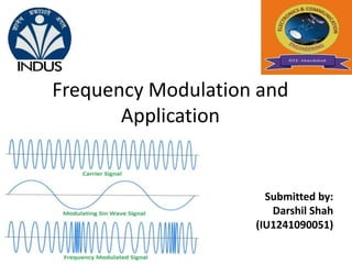
  • 1. Frequency Modulation and Application Submitted by: Darshil Shah (IU1241090051)
  • 2. Content 1. Flow diagram 2. What is frequency modulation? 3. Frequency modulation index 4. Significant-sidebands Spectrum 5. Types of FM 6. Generation of FM using PM 7. Advantages and disadvantages 8. Comparison with FM and PM 9. Applications
  • 3. Modulation Pulse Wave Modulation Amplitude Modulation Continuous Wave Modulation Linear Modulation Non-Linear Modulation Frequency Modulation Phase Modulation
  • 4. What is frequency modulation? When the frequency of carrier wave is changed in accordance with the message signal, The process is called frequency modulation. In FM the carrier amplitude remain constant the carrier frequency varies It is a type of Angle modulation Why Frequency modulation is called nonlinear-modulation?
  • 5.
  • 6. FM modulation index • FM modulation index is equal to the ratio of the frequency deviation to the modulating frequency. • Thus the formula for the modulation index for FM is simply given by that shown below: Frequency Deviation Modulating Frequency And also,
  • 7. Significant Sidebands – Spectrum • The table below shows the number of significant sidebands for various modulation  No of sidebands  1% of unmodulated carrier Bandwidth 0.1 2 2fm 0.3 4 4fm 0.5 4 4fm 1.0 6 6fm 2.0 8 8fm 5.0 16 16fm 10.0 28 28fm Example: For  = 5, 16 sidebands (8 pairs).
  • 8. Types of FM Narrow band FM 1. Narrow band FM is defined as the situation where the modulation index  is small. 2. From the table of Bessel functions it may be seen that for small , (  0.3) there is only the carrier and significant sidebands, i.e. BW = 2fm. FM with   0.3 is referred to as narrowband FM (NBFM). 3. Maximum modulating frequency is usually 3kHz 4. maximum frequency deviation is =75 kHz.
  • 9. Types of FM Wide band FM 1. Wideband FM is defined as the situation where the modulation index  is larger. 2. For  > 0.3 there are more than 2 significant sidebands. As  increases the number of sidebands increases. This is referred to as wideband FM (WBFM). 3. Modulation frequencies extend from 30 Hz to 15 kHz. 4. Maximum permissible deviation is=75 kHz. 5. Wideband FM system need large bandwidth, typically 15 times that of narrowband FM system.
  • 10. Generation of FM using PM Modulating Wave x(t) FM Wave Integrator Phase Modulator Carrier Oscillator dtt x ) (  Eccos(2fct)
  • 11. Advantages 1. Amplitude of the frequency modulated wave remains unaffected. 2. Large decrease in noise, hence increase in S/N ratio. 3. Noise may reduce by increasing deviation. 4. Frequency allocation allows for a guard band which reduces adjacent channel interference. 5. Operate In Very high frequency (VHF).
  • 12. Disadvantages • FM has too much advantages besides it also has some disadvantages 1. FM wave can’t cover large area. 2. Transmitting & receiving equipments for FM are complex & costly. 3. A much wider channel, typically 200 kHz, is needed for FM.
  • 13. Comparison of FM with PM Sr. No. FM PM 1 Frequency deviation is proportional to modulating voltage Phase deviation is proportional to the modulating voltage 2 Noise immunity is better than AM and PM Noise immunity is better than AM but worse than FM 3 SNR is better than PM SNR is worse than FM 4 FM is widely used for radio broadcasting PM is only used in some mobile systems 5 It is possible to receive FM on PM receive It is possible to receive PM on FM receive 6 Modulation index is proportional to modulating voltage as well as the modulating frequency . Modulation index is proportional to modulating voltage
  • 14. Comparison of FM and AM Sr. No. FM AM 1 FM receivers are immune to noise AM receivers are not immune to noise 2 It is possible to decrease noise by increasing deviation This feature is absent in AM 3 Bandwidth is higher and depends on modulation index Bandwidth is lower compared to AM but independent of modulation index 4 FM transmission and reception equipment are more complex FM transmission and reception equipment are less complex 5 All transmitted power is useful Carrier power and one sideband power is useless
  • 15. FM Radio FM radio uses a modulation index, m > 1, and this is called wideband FM. As its name suggests the bandwidth is much larger than AM. In national radio broadcasts using FM, the frequency deviation of the carrier  fc , is chosen to be 75kHz, and the information baseband is the high fidelity range 20Hz to 15kHz. BW of FM radio=2(75k+15k) =180khz Applications:
  • 16. Television Sound: In terrestrial TV broadcasts, the video information is transmitted using AM . However the sound information is transmitted using FM, in order to reduce possible interference between the video and sound signals. In this case, the maximum deviation of the carrier,  fc , is chosen to be 50kHz, and the information baseband is again the high fidelity range 20Hz to 15kHz. Therefore the bandwidth required for TV Sound is: BW Of TV Sound=2(50k+15k) =130khz Satellite TV. Some satellite TV transmissions broadcast an analogue video signal using FM. This helps to obtain an acceptable signal at the receiving station In this case, the maximum deviation of the carrier  fc , is chosen to be about 10 MHz, with a video baseband of around 5MHz. Therefore the bandwidth required for Satellite TV is: BW of satellite TV =2(10+5) =30Mhz
  • 17. References • http://www.silabs.com/Marcom%20Documents/Resources/FMTutorial.pdf • http://en.wikibooks.org/wiki/Communication_Systems/Frequency_Modulati on • http://www.radio-electronics.com/info/rf-technology-design/fm-frequency-modulation/ spectrum-bandwidth-sidebands.php • http://searchnetworking.techtarget.com/definition/frequency-modulation • https://www.youtube.com/watch?v=SmW4z76KgNQ • https://www.standrews.ac.uk/~www_pa/Scots_Guide/RadCom/part12/page 1.html • Analog and digital communication system by Sanjay Sharma. • Modern digital and analog communication systems by B.P. Lathi

Notas del editor

  1. Because frequency will be changed according to the baseband signal Because FM receiver may be filtered with amplitude limiters to remove the amplitude variation caused by noise this makes FM reception a good deal to immune noise. In AM this feature is absent 98.3 channel’s some interference will be get in both adjacent channels compare with FM in AM it will be very high 88Mhz to 108Mhz
  2. Delta f=k e & delta f= k e Refer advantages Refer advantages Application Vice-versa M=k e /f & M=k e
  3. 1 to 4 Advantages