

Recomendados
Más contenido relacionado
La actualidad más candente
La actualidad más candente (20)
Destacado
Destacado (20)
Similar a Rare earth doped fibers
Similar a Rare earth doped fibers (20)
Rare earth doped fibers
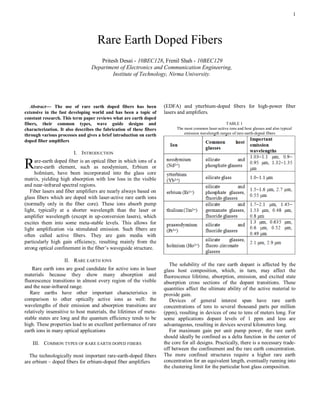
- 1. 1 Rare Earth Doped Fibers Pritesh Desai - 10BEC128, Frenil Shah - 10BEC129 Department of Electronics and Communication Engineering, Institute of Technology, Nirma University. Abstract— The use of rare earth doped fibers has been (EDFA) and ytterbium-doped fibers for high-power fiber extensive in the fast developing world and has been a topic of lasers and amplifiers. constant research. This term paper reviews what are earth doped fibers, their common types, wave guide designs and TABLE 1 characterization. It also describes the fabrication of these fibers The most common laser-active ions and host glasses and also typical through various processes and gives a brief introduction on earth emission wavelength ranges of rare-earth-doped fibers doped fiber amplifiers I. INTRODUCTION R are-earth doped fiber is an optical fiber in which ions of a rare-earth element, such as neodymium, Erbium or holmium, have been incorporated into the glass core matrix, yielding high absorption with low loss in the visible and near-infrared spectral regions. Fiber lasers and fiber amplifiers are nearly always based on glass fibers which are doped with laser-active rare earth ions (normally only in the fiber core). These ions absorb pump light, typically at a shorter wavelength than the laser or amplifier wavelength (except in up-conversion lasers), which excites them into some meta-stable levels. This allows for light amplification via stimulated emission. Such fibers are often called active fibers. They are gain media with particularly high gain efficiency, resulting mainly from the strong optical confinement in the fiber’s waveguide structure. II. RARE EARTH IONS The solubility of the rare earth dopant is affected by the Rare earth ions are good candidate for active ions in laser glass host composition, which, in turn, may affect the materials because they show many absorption and fluorescence lifetime, absorption, emission, and excited state fluorescence transitions in almost every region of the visible absorption cross sections of the dopant transitions. These and the near-infrared range. quantities affect the ultimate ability of the active material to Rare earths have other important characteristics in provide gain. comparison to other optically active ions as well: the Devices of general interest span have rare earth wavelengths of their emission and absorption transitions are concentrations of tens to several thousand parts per million relatively insensitive to host materials, the lifetimes of meta- (ppm), resulting in devices of one to tens of meters long. For stable states are long and the quantum efficiency tends to be some applications dopant levels of 1 ppm and less are high. These properties lead to an excellent performance of rare advantageous, resulting in devices several kilometres long. earth ions in many optical applications For maximum gain per unit pump power, the rare earth should ideally be confined as a delta function in the center of III. COMMON TYPES OF RARE EARTH DOPED FIBERS the core for all designs. Practically, there is a necessary trade- off between the confinement and the rare earth concentration. The technologically most important rare-earth-doped fibers The more confined structures require a higher rare earth are erbium – doped fibers for erbium-doped fiber amplifiers concentration for an equivalent length, eventually running into the clustering limit for the particular host glass composition.
- 2. . Clustering should be avoided as it induces fluorescence quenching and reduces the performance of the device. IV. WAVEGUIDE DESIGNS Let us consider the waveguide configurations used to bring Fig 1. Launching of Pump Light in Undoped Cladding the pump, signal, and active media together. The most widely used configuration consists of a rare earth doped fiber core, The guiding geometry of this configuration was designed to which allows the pump and signal to propagate together in a maximize the use of power available from laser diode arrays, single mode fiber; there are a number of alternative fiber thereby producing higher-output powers. device geometries worthy of consideration too. C. Evanescent Field A. Core Confined The wings or evanescent field of the optical signal guided In this type of waveguide design, both pump and signal by a single mode fiber may be used to interact with an active are confined in the fiber core for the most efficient conversion material outside of the core region. If the guide is tapered then of pump to signal photons. The most important features of this this effect can be enhanced thereby causing the optical power configuration is availability of commercial, low insertion loss, to increase outside the material bounds of the fiber over the low-reflectivity fiber couplers, which can be chosen to length of several millimeters. combine a variety of pump and signal wavelengths onto a Similarly, the active media can be incorporated in the common output fiber. cladding glass. Reported gain for an erbium-doped cladding For this design, the launched pump threshold power structure was 0.6 dB for a 1.55 um signal, with a 1.48 um Pth provides a reasonable figure of merit for the efficiency of a pump power of 50 mW. fiber laser or amplifier, a lower value being preferred. This The evanescent field may also be accessed by polishing quantity is proportional to away a portion of the fiber cladding, thus creating a structure similar to a D-shaped fiber. Pulsed amplification of 22 dB for (1) one such dye evanescent amplifier has been achieved To obtain a sizable gain, the pump power required for these devices exceeds that needed for schemes in which the active where, media are contained in the core. With the help of evanescent Aeff = effective core area interaction, active media such as dyes can be explored that εp = fractional absorbed pump power cannot be incorporated into a glass. σe = stimulated emission cross-section τf = pump fluorescence lifetime VI. CHARACTERIZATION OF RARE EARTH DOPED FIBERS The efficiency of this device, therefore, can be increased by In addition to all the properties of a passive (undoped) diminishing the effective core area, increasing the pump optical fiber, such as the guiding properties (effective mode absorption cross section, increasing the pump fluorescence area, numerical aperture, cut-off wavelength, and bend losses), lifetime, and increasing the stimulated emission cross section. nonlinearities, etc., active fibers can be characterized with The greatest effect on increasing the gain/pump power slope respect to several other properties: is observed by decreasing the mode field diameter (decreasing One of the most important parameters is the rare-earth Aeff) . Further improvement can be achieved by confining the doping concentration, most often specified in ppm wt (parts rare earth to the central portion of the core, where the pump per million by weight). A higher doping concentration allows and signal intensities are generally highest. for efficient pump absorption in a shorter length and thus also The optimized waveguide design then requires reduces the effect of nonlinearities in high peak power consideration of both the device configuration and a number devices. However, it can also lead to concentration quenching. of material and waveguide properties determined by the Wavelength-dependent effective absorption and emission fabrication methods used. cross sections (and possibly ESA cross sections) together with the upper-state lifetime (and possibly lifetimes of intermediate B. Double Clad levels) are required for calculating the wavelength tuning Another approach to achieve interaction of guided pump behaviour, power efficiency, etc. Parameters for quantifying light with an active medium, uses a single-mode guide or the the speed of energy transfer processes are important signal surrounded by a multimode pump guide. Pump light is particularly for co-doped fibers. launched from the fiber end into the undoped cladding, As an alternative method, Giles parameters can be propagating in a zigzag pattern through the doped core as it specified, which depend on the doping concentration, effective travels along the fiber. A high brightness neodymium fiber mode area and effective cross sections. laser based on the latter design provide an output greater than For such characterization, a variety of measurement 100 mW for an 807 nm diode array laser pump power of 500 techniques are used. White-light absorption spectra can be mW used for finding absorption cross sections (for known doping
- 3. 3 concentrations). Emission cross sections are obtained from VIII. RARE EARTH DOPED FIBER FABRICATION METHODS fluorescence spectra, with scaling e.g. via the reciprocity method or the meta-stable level lifetimes. Upper-state A. Low-Loss Communication Fiber lifetimes are often obtained from fluorescence measurements with pulsed pumping, and ESA parameters can be obtained in The standard method of fabricating doped silica fiber fall experiments with a modulated pump power. into two basic categories, both based on the reaction of The resulting set of data can be used e.g. in laser and halides, such as SiCl4, GeCl4, POCl3, SiF4, and BCl3, to form amplifier models based on rate equations. Such models allow the desired mix of oxides. one, e.g. to predict or check the performance of fiber laser or Category 1 reacts the chlorides in a hydrogen flame and amplifier devices, the effect of possible modifications etc. collects the resulting soot on a mandrel for subsequent Further characterization may be required for quantifying sintering to a transparent glass. Processes based on this effects such as photo darkening, which can sometimes method are commonly referred to as vapor axial deposition seriously degrade the efficiency of active fiber devices. (VAD) and outside vapor deposition (OVD). Category 2 reacts the chlorides inside a substrate tube that VII. RARE-EARTH-DOPED FIBER AMPLIFIERS becomes part of the cladding, simultaneously reacting, depositing, or sintering as a torch plasma fireball or With the development of fibers that amplify light through microwave cavity traverses the tube. Processes based on this stimulated emission, a new fiber technology came into method are commonly referred to as modified chemical vapor existence. Due to it, channel capacities of the fiber deposition (MCVD), plasma chemical vapor deposition communication increased. (PCVD), and intrinsic microwave chemical vapor deposition Such fibers are made by incorporating various rare-earth ion (IMCVD). dopants into the core material, the most successful of which All these methods create a preform, or large-geometry has been erbium. Erbium-doped fiber amplifiers (EDFAs) in equivalent, which is desired in the fiber. The preform is then their usual configuration provide gain that maximizes at 1.53 drawn into an optical fiber by heating one end to the softening um when the fiber is pumped by additional light input at either temperature and pulling it into a fiber at rates of 1-10 m/s. 1.48 or 0.98 um wavelength. Lengths of amplifying fibers are Index-raising dopant ions, such as germanium, phosphorus, used as repeater sections in communications systems, aluminium, and titanium, and index-lowering dopants such as replacing the expensive and complicated electronic units that boron and fluorine, are introduced into the reaction stream as were commonly used. halide vapors carried by oxygen at a temperature near 30°C. The main advantage of using a fiber amplifier repeater is The halide compounds of rare earth ions are, however, that the transmitted signal will remain in optical form generally less volatile than the commonly used chlorides and throughout the link rather than being transformed into an fluorides of the index-modifying dopants, thereby requiring electrical signal and back to optical signal whenever a repeater volatilizing and delivering temperatures of a few hundred stage is encountered. System data rates can also be changed as degrees. per need or simultaneously multiple data rates can be transmitted without the need to modify the transmission span. A single EDFA can provide gain for multiple wavelengths simultaneously. Such a task would otherwise require a separate electronic repeater for each wavelength. It is this feature that contributed to the realization of dense wavelength division multiplexed (DWDM) systems. For example, 80 wavelength channels having 50 GHz spacing can be accommodated within the conventional 1.53 to 1.56 um EDFA gain bandwidth. More recent efforts have resulted in the extension of EDFA gain into the longer wavelength (L band) range between 1.56 and 1.63 um. Other rare-earth dopants or dopant combinations have been used to produce fiber amplifiers that pose gain at other wavelengths in the visible and near-infrared. Examples of these include praseodymium-doped fiber amplifiers (PDFAs), which provide gain at 1.3 um and are pumped at 1.02 um. Ytterbium-doped fibers (YDFAs) amplify from 975 to 1150 nm using pump wavelengths between 910 and 1064 nm; Fig 2. Vapor pressures of reactant halides, including index- erbium-ytterbium co-doped fibers (EYDFAs) enable use of raising ions and a representative rare earth ion, Er pump light at 1.06 um while providing gain at 1.55 um. Thulium-doped fluoride fibers (TDFAs) have been constructed for amplification at 0.8 um and 1.48 um.
- 4. B. Rod and Tube The first optical fiber was made by drawing a preform assembly made of a core rod and cladding tube of the proper dimensions and indices. Recent adaptations of this method have been demonstrated for making compound glass core compositions. To retain the overall compatibility with communication-grade doped silica fiber, a small compound glass rod is inserted into a thick-walled silica tube. The combination is then drawn at the high temperatures required by the silica tube. As a result, a few of the less stable constituents of the compound glass are volatilized. In spite of this, lengths of fiber can be drawn that are long enough for practical use. With interest in distributed Er-doped amplifiers, a need arose for a method to produce uniform and very low dopant levels. Although the solution doping and outside process methods were successful in controlling these low levels of dopant, a new, rod-and-tube like technique was also devised to meet this challenge. Here rare earth was introduced into an MCVD preform as the core of a fiber with a 150 um outside Fig 3. Seed fiber doping of MCVD diameter and a 10 um core diameter (see the figure below). The “seed” fiber was inserted in the bore of an MCVD preform before the last collapse pass. During the final collapse REFERENCES pass, the fiber becomes a diffusion source for the dopant ions [1] T. Setsuhisa, “Development of Rare Earth-doped fiber in the center of the preform core. amplifiers”, IPAP books 2 (2005) pp. 101–112. Fibers fabricated by this method have shown losses as low [2] Chu, Pak Lim,” Nonlinear effects in rare-earth-doped fibers and as 0.35 dB/km and well-controlled erbium levels of 0.01 ppm waveguides”. Er3+, corresponding to a ground-state absorption level of only [3] Urquhart, Paul,” Review of rare earth doped fibre lasers and amplifiers”. 1 dB/km at 1.53 um. Ina sense this resembles a miniature rod- [4] Agrawal, Nonlinear Fiber Optics (Second Edition), California, and-tube process except that the rod is effectively dissolved in USA. the host core, as evidenced by the change in fluorescence [5] Digonnet, Rare-Earth-Doped Fiber Lasers and Amplifiers spectrum from the seed composition to the core composition. (Second Edition), New York, USA. [6] Rare Earth Doped Fibers, http://www.fiberforsale.com, 14-03- 2013