SlideShare una empresa de Scribd logo
1 de 35
OrCad and Hyperlynx; Quality Management Systems,
                           and CodeWarrior, Linux
                                                                        By JB
            (Rev1.0)

            Contents
Schematic Input with OrCad and Simultation with Mentor Hyperlynx Tools...............................................2
OrCad Projects.............................................................................................................................................2
OrCad Project Schematic Drawing Example.................................................................................................3
HyperLynx Pre- and Post-Layout Simulation of Schematics.........................................................................5
Design Verification in the Lab......................................................................................................................6
The Freescale PowerQuicII Pro 8313 RDB Board with Linux and Codewarrior IDE......................................6
Board Hardware Features............................................................................................................................7
An Example 8313 Application: Printer CPU..................................................................................................9
The Freescale 8313 PowerPC.....................................................................................................................10
Codewarrior for 8313 RDB.........................................................................................................................11
UBOOT and the Freescale Linux Board Support Package...........................................................................12
Compiling and downloading 8313 RDB Software......................................................................................13
8313RDB Configuration File Contents........................................................................................................13
QMS TOOLS...............................................................................................................................................23
HP Quality Center......................................................................................................................................24
   Tracking and Reporting Capabilities.......................................................................................................25
   HP Quality Center components.............................................................................................................26
   Enterprise Management Software Development Support....................................................................28
TELEOGIC DOORS Requirements Management System.............................................................................29
Software Modification and Change Control Tracking Tools (Example: Siebel)..........................................30
BORLAND TOOLS - CaliberRM....................................................................................................................32
   CaliberRM..............................................................................................................................................34
Useful Links................................................................................................................................................35
Schematic Input with OrCad and Simultation
with Mentor Hyperlynx Tools


This technical note describes OrCad features for
drawing schematics and Mentor Hyperlynx Line Sim
and Board Sim tools for simulation of critical nets and
buses.


OrCad Projects


OrCad saves a set of drawings as a “project.”
Two project types are available:
  • Basic digital schematics
  • Schematics with analog and digital parts.

Project libraries are maintained by OrCad which
contain a copy of cached part models from the parts
database or library.

Each part has a list of attributes that can be edited,
including the part reference designators, values,
package types, and manufacturer.

OrCad can generate a BOM and also provides input to
OrCad layout tools.
OrCad Project Schematic Drawing Example


OrCad allows one to place parts on schematic pages
using a database library. The library can be extended
by drawing your own parts and adding them to the
database or buy purchasing on-line access to an
extensive database of parts for a wide variety of
applications.

The drawing below is an 80251 schematic in progress.
(The page shown is in progress; some additional
connections are required to connect chip enables,
port mode selection, and external timers and
interrupt pins.)

The 80251 has 4 optional ports. Using internal ROM,
all four ports can be enabled for external access to
other parts in the application.

External ROM, RAM, and I/O parts can also be
addressed. Chip enables allow the designer to access
individual external parts conveniently.

Timer outputs T0-T2 permit the user to output strobe
signals with pre-programmed timing. The 802551 also
has programmable interrupts when the timers expire.
Timers can be programmed to re-initialize and
continue. Interrupts can occur repetitively or upon a
single timer count down.
A synchronous WAIT input halts the processors
transactions.

The 80251 also has two Interrupt inputs that permit
the microcontroller to serve external functions on
demand.

Using the extended addressing capability of this 80251
microcontroller, A0-A17 are available. This permits
addressing of up to 256KB of address space.
HyperLynx Pre- and Post-Layout Simulation
of Schematics


In some cases, schematic pages contain high speed
transmission lines. (The circuit above does not contain
high speed components.)

Before layout, Mentor Hyperlynx Line Sim can be used
to stimulate and measure the characteristics of high
speed signals, including ringing, crosstalk, and other
characteristics.

Mentor Hyperlynx Board Sim is a post layout tool
which takes into account the actual routing netlist and
board geometry prepared by Mentor layout tools for
PADS schematics or OrCad family layout tools
(Allegro).

Hyperlynx uses models available directly from
manufacturers (IBIS) or user constructed table based
models, among the numerous model types supported.

Hyperlynx wizards are available to quickly map net list
sections to key components to be simulated in board
sim. An example is the Hyperlynx DDR3 Wizard, which
helps users measure performance of DDR3 memories
which can use clock rates in the gigahertz range.
Design Verification in the Lab


Design verification should be conducted on the bench
to compare hyperlynx board sim results with actual
prototype signal characteristics measured using
storage scopes for measuring buses, eyes on critical
signals, and transmission line characteristics.


The Freescale PowerQuicII Pro 8313 RDB
Board with Linux and Codewarrior IDE


This tech note page describes the Motorola 8313 RDB
board with Linux RTOS in flash.
It describes the board features, how to use UBOOT to
launch Linux, and how to download and execute
software written using the Codewarrior IDE.
Motorola describes the 8313 processor as follows:
“The MPC8313E communications processor family
meets the requirements of several small office/home
office (SOHO), printing, IP services and industrial
control applications.”
Freescale 8313 RDB Board with 8313 processor


Board Hardware Features


The lists below were reproduced from Motorola’s specs,
with the authors comments.
Processor:
     * Freescale MPC8313E running at 333/333 MHz (CPU/
     DDR2) - DDR2 memories are capable of speeds to
     about 400MHz. Data is clocked on each edge.

Memory:
   * 128 MByte unbuffered DDR2 SDRAM discrete
   devices – close proximity to memory controller.
   * 8 MByte Flash single-chip memory
   * 32 MByte NAND Flash memory
* 256 KBit M24256 serial EEPROM
     * SD connector to interface with the SD memory card
     in SPI mode - SPI interfaces include clock, input, and
     output; data can be clocked in and out
     simultaneously.

Interfaces:
     * 10/100/1000 BaseT Ethernet ports: (Two external
     interface modes. The RGMII interface is used with an
     external switch to support five Ethernet ports.
           o 8313 eTSEC1, RGMII interface: five
           10/100/1000 BaseT RJ-45 interfaces using
           Vitesse™ VSC7385 L2 switch
           o 8313 eTSEC2, selectable RGMII or SGMII
           interface: one 10/100/1000 BaseT RJ-45
           interface using Mavell™ 88E1111 PHY
     * USB 2.0 port: (On chip or off chip PHY hardware.)
           o High speed host/device USB interface:
           selectable on-chip PHY or external ULPI PHY
           interface by SMSC USB3300 USB PHY
     * PCI: 32-bit PCI interface running at up to 66 MHz
     (PCI is a PCISIG standard)
           o One 32-bit 3.3 V PCI slot connected to PCI bus
           o One 32-bit 3.3 V miniPCI slot connected to PCI
           bus
     * Dual UART ports:
           o DUART interface: supports two UART up to
           115200bps for console display – Can be
           displayed using PC serial port and hyperterminal.
Board connectors:
    * LCD connectors by GPIO
    * ATX power supply connector – 5V input only.
    * JTAG/COP for debugging – uses Codewarrior USB
    Tap interface


   Freescale 8313 RDB Board with 8313 processor


An Example 8313 Application: Printer CPU


The 8313 can be used as a network or USB printer
CPU. User data to be printed can be manipulated in
RAM, and printer imaging controls can be accessed via
a local bus interface to an ASIC or FPGA with interface
logic.
A simple text LCD can be controlled via the GPIO
interface.
An external Ethernet PHY module can be used to
interface the printer to a network, if required. One of
the built-in USB interfaces can be used to wake up the
printer upon activity.


The Freescale 8313 PowerPC


The 8313 RDB contains a PowerQuicII core. An 8313
block diagram is reproduced below.


              MPC8313E Block Diagram
(reproduced from FS website)

The e300 core has an L1 16K instruction cache and a
separate L1 16K data cache.
The e300 Core power is approximately 1.2W. Standby
power is less than 300mW.
PowerQuicII pro devices such as the 8313E include a
security feature module.
The processor can boot from NOR or NAND devices and
includes one SPI interface and two I2C interfaces.
The IC circuits include 4 DMA controllers that support I/O,
and a built-in programmable interrupt controller.


Codewarrior for 8313 RDB


The Codewarrior RDB includes a project creation
wizard that allows one to automatically include
libraries with drivers for devices on the 8313RDB.
Users can select C or C++ code.

Freescale provides source code modules that can be
edited for re-use, including main.cpp, interrupt.c, and
sc_handler.c (a system call handler).

After the user selects “make,” the “run” command
accesses the Freescale USB tap development interface
to download and begin execution of user code.
‘
UBOOT and the Freescale Linux Board
Support Package


UBOOT permits users to download files.

UBOOT is loaded into the RDB DDR memory then
flashed into the RDB flash memory using commands
described in Freescale application note AN3947.
UBOOT is configured for NFS deployment in the
process, which allows networking commands to be
used for the download process.
Steps to prepare the Freescale Linux BSP (Board
Support Package) include:
  • Download the appropriate BSP
  • Build the kernel
  • Modify the device tree files for the board rev.
  • Place kernel and device tree in a directory for
    downloading later.

Additional steps before downloading the Linux kernel
include using the setenv command to configure the
host.


Compiling and downloading 8313 RDB
Software


After the Linux kernel is appropriately installed, users
can compile C or C++ code using Codewarrior and
appropirate RDB interface drivers, make the package,
and then use the “run” command to download it to
the RDB. The console makes use of a serial port for
user input and feedback during program operation.


8313RDB Configuration File Contents


Here are the contents of the 8313RDB configuration
file:
#setMMRBaseAddr 0xFF400000
writereg MBAR    0xFF400000

# change internal MMR base from
0xff400000 (reset value) to
0xe0000000
writemem.l 0xff400000 0xe0000000 #
IMMRBAR = 0xe0000000

#setMMRBaseAddr 0xe0000000
writereg MBAR    0xe0000000


####################################
##########
# System Configuration - Local
Access Windows
####################################
##########

# Local Bus Local Access Windows
#################################
# WINDOW 0 - NOR FLASH
writemem.l 0xe0000020 0xfe000000 #
LBLAWBAR0 - begining at 0xfe000000
writemem.l 0xe0000024 0x80000018 #
LBLAWAR0   - enable, size = 32MB

# WINDOW 1 - NAND Flash
writemem.l   0xe0000028 0xf8000000 #
LBLAWBAR1    - begining at 0xf8000000
writemem.l   0xe000002c 0x80000018 #
LBLAWAR1     - enable, size = 32MB

# WINDOW 2   - VSC7385
writemem.l   0xe0000030 0xf0000000 #
LBLAWBAR2    - begining at 0xfc100000
writemem.l   0xe0000034 0x80000010 #
LBLAWAR2     - enable, size = 128kB

# WINDOW 3   - Read Write Buffer
writemem.l   0xe0000038 0xfa000000 #
LBLAWBAR3    - begining at 0xfa000000
writemem.l   0xe000003c 0x8000000e #
LBLAWAR3     - enable, size = 32kB

# PCI Local Access Windows
#################################
# WINDOW 0
writemem.l 0xe0000060 0x80000000 #
PCILAWBAR0 - begining at 0x80000000
writemem.l 0xe0000064 0x8000001c #
PCILAWAR0 - enable, size = 512MB

# WINDOW 1
writemem.l   0xe0000068 0xa0000000 #
PCILAWBAR1   - begining at 0xa0000000
writemem.l   0xe000006c 0x8000001c #
PCILAWAR1    - enable, size = 512MB
# DDR Local Access Windows
#################################
# WINDOW 0 - 1st DDR SODIMM
writemem.l 0xe00000a0 0x00000000 #
DDRLAWBAR0 - begining at 0x00000000
writemem.l 0xe00000a4 0x8000001a #
DDRLAWAR0 - enable, size = 128MB


#*********************************
   # DDR2 Controller Registers

#*********************************

   #DDRCDR
   writemem.l 0xE0000128 0x73000002

   # DDR_SDRAM_CLK_CNTL
   # CLK_ADJST = b'010' ; 2 Clocks
        writemem.l 0xE0002130
0x02000000

   # CS0_BNDS
   # SA0 = b'000000000000'
   # EA0 = b'000000000111'
   writemem.l 0xE0002000
0x00000007 ;# 128MB

   # CS0_CONFIG
   # CS_0_EN = b'1'
   # AP_0_EN = b'1'
# ODT_RD_CFG = b'0'
   # ODT_WR_CFG = b'1'
   # BA_BITS_CS_0 = b'00'
   # ROW_BITS_CS_0 = b'001' ; 13 row
bits
   # COL_BITS_CS_0 = b'010' ; 10
columns bits
   writemem.l 0xE0002080 0x80840102

   # TIMING_CFG_3
   # EXT_REFREC = b'000' ; 0 Clocks
   writemem.l 0xE0002100 0x00000000


   # TIMING_CONFIG_1
   # bit 1-3 = 2 - PRETOACT
precharge activate interval 2 clock
cycles
   # bit 4-7 = 6 - ACTTOPRE activate
to precharge interval 6 clock cycles
   # bit 9-11 = 2 = ACTTORW activate
to r/w interval 2 clock cycles
   # bit 13 - 15 = 5 - CASLAT CAS
latency 3 clock cycles
   # bit 16 - 19 = 6 - REFREC
refresh recovery time 14 clock
cycles
   # bit 21 - 23 = 2 - WRREC data to
precharge interval 2 clock cycles
# bit 25 - 27 = 2 - ACTTOACT
activate to activate interval 2
clock cycles
   # bit 29 - 31 = 2 - WRTORD write
data to read command interval 2
clock cycles
   writemem.l 0xe0002108 0x26256222

   # TIMING_CONFIG_2
   # bit 19-21 = b010 -
WR_DATA_DELAY - 1/2 DRAM clock delay
   writemem.l 0xe000210C 0x0f9028c7


   # TIMING_CFG_0
   # RWT = b'00' ; 0 Clocks
   # WRT = b'00' ; 0 Clocks
   # RRT = b'00' ; 0 Clocks
   # WWT = b'00' ; 0 Clocks
   # ACT_PD_EXIT = b'010' ; 2 Clocks
   # PRE_PD_EXIT = b'010' ; 2 Clocks
   # ODT_PD_EXIT = b'1000' ; 8
Clocks
   # MRS_CYC = b'0010' ; 2 Clocks
   writemem.l 0xE0002104 0x00220802

   #   DDR_SDRAM_CFG
   #   MEM_EN = b'0'
   #   SREN = b'1'
   #   RD_EN = b'0'
# SDRAM_TYPE = b'011'
   # DYN_PWR = b'0'
   # 32_BE = b'1'
   # 8_BE = b'0'
   # NCAP = b'0'
   # 2T_EN = b'0'
   # x32_EN = b'0'
   # PCHB8 = b'0'
   # HSE = b'0'
   # MEM_HALT = b'0'
   # BI = b'0'
   writemem.l 0xE0002110 0x43080000

   # DDR_SDRAM_CFG_2
   # FRC_SR = b'0'
   # DQS_CFG = b'00'
   # ODT_CFG = b'10'
   # NUM_PR = b'0001'
   # D_INIT = b'0'
   writemem.l 0xE0002114 0x00401000

   # DDR_SDRAM_MODE
   # Extended Mode Register:
Outputs=0 or 1?
   # Mode Register
   writemem.l 0xE0002118 0x44400232

   # DDR_SDRAM_MODE_2
   # Extended Mode Register 2
   # Extended Mode Register 3
   writemem.l 0xE000211C 0x8000c000
# DDR_SDRAM_INTERVAL
   # REFINT = 800 Clocks
   # BSTOPRE = 100 Clocks
   writemem.l 0xE0002124 0x03200064

   #delay before enable
   sleep 300
   #Enable: DDR_SDRAM_CFG
   writemem.l 0xE0002110 0xc3080000


####################################
##########
# Local Bus Interface (LBIU)
Configuration
####################################
##########

# CS0 - 8MB NOR FLASH
writemem.l 0xe0005000 0xfe001001 #
BR0 base address at 0xFE000000, port
size 16 bit, GPCM, valid
writemem.l 0xe0005004 0xfe006ff7 #
OR0 8MB flash size, 15 w.s., timing
relaxed

# CS1 - NAND FLASH
writemem.l   0xE0005008
   0xF8000C21 # BR1 base address at
0xF8000000, port size 8 bit, FCM,
valid
writemem.l   0xE000500c
   0xFFFF83CC # OR1 32KB flash size,
small page
#for a Rev A board, please comment
the line above and use the below
initialization for OR1:
#writemem.l 0xE000500c
   0xFFFF93CC # OR1 32KB flash size,
small page

# CS2 - VSC7385
writemem.l 0xe0005010 0xf0000801 #
BR2 base address at 0xF0000000, port
size 8 bit, GPCM, valid
writemem.l 0xe0005014 0xFFFE09FF #
OR2 128KB

# CS3 - Read Write Buffer
writemem.l 0xe0005018 0xfa000801 #
BR3 base address at 0xfa000000, port
size 8 bit, GPCM, valid
writemem.l 0xe000501c 0xFFFF8FF7 #
OR3 32KB

# LBCR - local bus enable
writemem.l 0xe00050d0 0x00000000

# LCRR
# bit 14 - 15 = 0b11 - EADC - 3
external address delay cycles
# bit 28 - 31 = 0x0010 - CLKDIV -
system clock:memory bus clock = 2
writemem.l 0xe00050d4 0x00030002


writereg MSR 0x2000 # FP available,
machine check disable, exception
vectors at 0x0000_0000

writemem.l 0xE0000800 0x00000000 #
ACR - Enable Core


writemem.l 0xfa000000 0x00000000 #
write board LEDs

#
# NAND Flash settings
#
writemem.l   0xE00050E0
   0x0000E000 # FMR


# MRTPR - refresh timer prescaler
writemem.l 0xe0005084 0x20000000


writereg SP 0xf
QMS TOOLS


In product development and test methodologies,
documentation is hierarchical:
  • Requirements
  • Specifications
  • Test Plans

Automated tools permit businesses to manage
release contents for multiple products, assigning
software component versions and also re-usable
tests to cover the requirements for multiple
products, and to assess the risks and issues
(defects) in product releases.


Using enterprise level tools, business planners
can schedule development and testing of
multiple projects more effectively by taking into
account the status, defects, and tests needed for
each product to plan and accomplish order
(sales delivery) goals effectively.
HP Quality Center


HP Quality Center features include means to:
  •   manage project requirements and their
      changes
  •   track software development progress
  •   Assess risk
  •   Plan software release contents

HP Quality Center capabilities are analogous to
Borland Project Lifecycle Management tools.


HP Quality center can be used across distributed
organizations. HP Quality Center supports:
  • Centralized release management and
    version numbering of large software
    products across the organization.
  • Ability to assign versions of software
    components created in different groups to
    the builds for specific products.
  • Ability to assign versions of tests for
    software components to specific product
    releases, re-using existing tests and test
    scripts.
• Ability to re-use tests and test scripts for
    different products.
  • Ability to keep track of bugs and defects for
    each product in a centralized database,
    based upon its specific software component
    versions and test script test status/results.
  • Risk assessment is possible for a given
    product release using this information.


All software components have their own version
numbers. Tests and Test scripts are assigned
their own release and version numbers also.


Tracking and Reporting Capabilities
Using linked information and database analysis,
HP Quality Center provides the ability to assess:
  • Requirements coverage by units and
    modules the product comprises. Defects
    affecting requirements are visible.
  • Reporting capabilities provide ways to share
    info
  • Large QA efforts can make use of these
    tools across a network for collaboration to
    succeed.
• Workflows through the lifecycle provide
    standardized repeatable methods.

By including tools supporting each portion of the
product lifecycle, consistent, repeatable QA can
be performed on software successfully.


As with all development methodology tools, the
ability to find defects more easily before
production is a strong advantage.


HP Quality Center components


       • The Quality Center Foundation – basic
         platform for workflow rules. Can be
         configured for your business
         environment.


       • HP TestDirector (was in v9; now part of
         V10 without using this name)– Used to
         manage requirements, plan and
         schedule tests (assigning test assets to
         requirements), reporting results, and
         reporting on defects and issues to
         facilitate planning and risk assessment.
• Functional Test components – permit
  advanced automated functional
  testing and regression testing. A
  special module supports enterprise IT
  applications.


• HP Business Process Testing software –
  allows business analysts and other
  planners to analyze business use cases
  of software products and the process
  flows involved with creating multiple
  products (with insight into scheduling
  based upon status of all tests and
  components). This permits scheduling
  of test development to proceed in a
  manner which facilitates success
  across the product line and software
  release roll-out for multiple products
  (thanks to a single large QC repository
  of info available).
• Using HP Quality Center, one can
  identify and schedule tests needed to
  address the impact of changes, so
application quality is increased and risk
        is minimized.


Enterprise Management Software
Development Support
       HP Quality Center can make use of SAP
        and SOA extensions to support SAP,
        SOA, and Oracle® quality
        management.
       As with all software developed using
        HP Quality Center, one can identify
        and schedule tests needed to address
        the impact of changes, so application
        quality is increased and risk is
        minimized.

       HP Service Test components – An
        advanced quality management
        package, covering SOA test
        management, requirements, defects
        tracking, functional testing, regression
        testing and business process design
        validation.
TELEOGIC DOORS Requirements
Management System


Teleogic Doors uses a database with linked,
numbered sections for each product
development milestone document; e.g. Market
requirements, Engineering system requirements,
hardware and software unit specifications, and
test plan test cases. Each are numbered and
linked together.


With doors, one can verify that a test case
covers or “traces” back to each requirement or
specification above.


One can also verify which section of
specifications documents cover product system
level requirements.


(the name “Doors” refers to the ability to jump
or link between project hierarchical documents).
This tool was introduced in the late 1990’s. It is
best for product development and checking
traceability of hierarchical documents.
Software Modification and Change Control
Tracking Tools (Example: Siebel)


Tools in this category assist system developers
by keeping track of software change requests
and their status. Siebel is an example of a basic
MR tracking tools. Siebel allows users to
conveniently enter MR’s, assign priorities, and
owners.


A project team member is assigned as MR
change control administrator/tracker.
MR’s pass through a series of steps that are user
definable, and may include:


Open (by originator)
  •   UI (owner)
  •   Fixed (new owner is tester)
  •   Verified (owner
  •   Closed (MR admin)

Other MR assignments might include:
  • Defer
In the case of defer, the project team leadership
decides which release to phase changes into.


Useful information catalogued with entries in
software change control databases include:
  • Description of problem
  • How to reproduce problem
  • Area impacted (as specific as possible; a
    software module)
  • Severity (critical, high, medium, low; or 1-4)
    – Critical changes require prompt
    investigation.
  • Impact of problem: who is affected where
  • Customer who reported problem and notes
    about their needs.

Siebel and other MR tracking tools allow users to
print reports sorted by severity, status (open, UI,
etc), and other fields.


As change control tracking on PBX and large
ATM switch projects at Bell Labs and ViaGate
Technologies, I used tools to track MR status and
priorities. As senior systems engineer in the
software development group at ViaGate, I was
responsible for planning software release
contents for a period of time early in the initial
product shipment timeframe. This involved
working with engineers, marketing and
engineering management closely to evaluate
status and make decisions about release
contents for our ATM switch.
The ViaGate switch used 12 unix multiprocessing
boards, and provided internet, video (CATV
lineup), and VLAN access to up to 240
subscribers using set top boxes and VDSL
modems. The switch was designed for use in
basements, and connected to the telco by Sonet
fibers.


ViaGate Product Description
(Telecommunication Switch for Internet, VLAN,
and Video Access to 240 Subscribers)
http://www.jbmsee.net/reslib/ViaGateNode.ht
m


BORLAND TOOLS - CaliberRM


Borland makes leading Windows software
compiler IDE tools in competition with
Microsoft.
Borland has entered the market with software
lifecycle management tools.


Tools include these aspects of development:
  • Requirements definition and management
  • Testing, software release planning, and risk
    assesment

Borland’s testing and ASQ tools help automate
planning/tracking in these areas:
  • Requirements based testing
  • Software Test Management (planning,
    documentation of test processes)
  • Software Development Metrics – to assist
    managers
  • Test Automation – tools to help automate
    developer (unit), functional (system and
    integration testing), and performance
    testing (product quality/verification). This is
    accomplished by tools that support each
    step in the workflow.
(from Borland site)


     CaliberRM


During the fall of 2003, I attended a training and
info seminar on Borland compilers and software
development project tools. These tools assist
requirements traceability, change tracking,
release planning, and risk assessment. Borland
has attempted to provide tools for each
essential workflow step, allowing project
managers to track status of large projects in an
organization.


The CaliberRM tools is used for requirements
management, and provides network based
means to collaborate between users on large
projects. CaliberRM allows users to enter
detailed info about unit modules and their
development status.
Borland also HP Quality Center components (The
“Quality Center Foundation, “ HP TestDirector
for HP Quality Center, and Extensions for SAP
and SOA)


Useful Links
Doors
http://www.wbbinc.com/doors_requirements_
management.html


HP Quality Center
http://h50281.www5.hp.com/software/index.ht
ml


Borland Project Management Tools
http://www.borland.com/us/solutions/requirem
ents-definition-management/index.html


(copyright)

Más contenido relacionado

La actualidad más candente

OVERVIEW OF MSP430G2553
OVERVIEW OF MSP430G2553OVERVIEW OF MSP430G2553
OVERVIEW OF MSP430G2553shams tabrez
 
Introduction of microcontroller
Introduction of microcontrollerIntroduction of microcontroller
Introduction of microcontrollerEngineer Maze
 
Introduction to msp430
Introduction to msp430Introduction to msp430
Introduction to msp430Harsha herle
 
eCOG1X 16-bit Microcontrollers
eCOG1X 16-bit MicrocontrollerseCOG1X 16-bit Microcontrollers
eCOG1X 16-bit MicrocontrollersPremier Farnell
 
Tft touch screen manufacturers
Tft touch screen manufacturersTft touch screen manufacturers
Tft touch screen manufacturersKeatonParker2
 
Unit 1 embedded systems and applications
Unit 1 embedded systems and applicationsUnit 1 embedded systems and applications
Unit 1 embedded systems and applicationsDr.YNM
 
Microcontroller
MicrocontrollerMicrocontroller
MicrocontrollerSpitiq
 
TFT LCD Module Display Manufacturer
TFT LCD Module Display ManufacturerTFT LCD Module Display Manufacturer
TFT LCD Module Display ManufacturerKeatonParker2
 
Embedded systems notes
Embedded systems notesEmbedded systems notes
Embedded systems notesShikha Sharma
 
Introduction to Microcontrollers
Introduction to MicrocontrollersIntroduction to Microcontrollers
Introduction to Microcontrollersmike parks
 
Introduction to embedded system
Introduction to embedded systemIntroduction to embedded system
Introduction to embedded systemNiteesh Srivastava
 
Microbots: microcontroller msp430
Microbots: microcontroller msp430Microbots: microcontroller msp430
Microbots: microcontroller msp430crisurdiales
 

La actualidad más candente (20)

OVERVIEW OF MSP430G2553
OVERVIEW OF MSP430G2553OVERVIEW OF MSP430G2553
OVERVIEW OF MSP430G2553
 
Introduction of microcontroller
Introduction of microcontrollerIntroduction of microcontroller
Introduction of microcontroller
 
2 unit-es-printed
2 unit-es-printed2 unit-es-printed
2 unit-es-printed
 
Atmega8u2 mur
Atmega8u2 murAtmega8u2 mur
Atmega8u2 mur
 
Introduction to msp430
Introduction to msp430Introduction to msp430
Introduction to msp430
 
eCOG1X 16-bit Microcontrollers
eCOG1X 16-bit MicrocontrollerseCOG1X 16-bit Microcontrollers
eCOG1X 16-bit Microcontrollers
 
Psoc3 text book
Psoc3 text book Psoc3 text book
Psoc3 text book
 
Seminar
SeminarSeminar
Seminar
 
Tft touch screen manufacturers
Tft touch screen manufacturersTft touch screen manufacturers
Tft touch screen manufacturers
 
Unit 1 embedded systems and applications
Unit 1 embedded systems and applicationsUnit 1 embedded systems and applications
Unit 1 embedded systems and applications
 
3.TechieNest microcontrollers
3.TechieNest  microcontrollers3.TechieNest  microcontrollers
3.TechieNest microcontrollers
 
Microcontroller
MicrocontrollerMicrocontroller
Microcontroller
 
TFT LCD Module Display Manufacturer
TFT LCD Module Display ManufacturerTFT LCD Module Display Manufacturer
TFT LCD Module Display Manufacturer
 
Embedded systems notes
Embedded systems notesEmbedded systems notes
Embedded systems notes
 
Interfacing using ِAtmega16/32
Interfacing using ِAtmega16/32 Interfacing using ِAtmega16/32
Interfacing using ِAtmega16/32
 
Avr introduction
Avr introductionAvr introduction
Avr introduction
 
8 bit microcontroller
8 bit microcontroller8 bit microcontroller
8 bit microcontroller
 
Introduction to Microcontrollers
Introduction to MicrocontrollersIntroduction to Microcontrollers
Introduction to Microcontrollers
 
Introduction to embedded system
Introduction to embedded systemIntroduction to embedded system
Introduction to embedded system
 
Microbots: microcontroller msp430
Microbots: microcontroller msp430Microbots: microcontroller msp430
Microbots: microcontroller msp430
 

Similar a CodeWarrior, Linux; OrCad and Hyperlynx; QMS Tools

Rodrigo Almeida - Microkernel development from project to implementation
Rodrigo Almeida - Microkernel development from project to implementationRodrigo Almeida - Microkernel development from project to implementation
Rodrigo Almeida - Microkernel development from project to implementationFelipe Prado
 
INDUSTRIAL TRAINING REPORT EMBEDDED SYSTEM.pptx
INDUSTRIAL TRAINING REPORT EMBEDDED SYSTEM.pptxINDUSTRIAL TRAINING REPORT EMBEDDED SYSTEM.pptx
INDUSTRIAL TRAINING REPORT EMBEDDED SYSTEM.pptxMeghdeepSingh
 
Overview of Microcontroller and ATMega32 microcontroller
Overview of Microcontroller and ATMega32 microcontrollerOverview of Microcontroller and ATMega32 microcontroller
Overview of Microcontroller and ATMega32 microcontrollerRup Chowdhury
 
4 Channel Relay Board 5V-Bluetooth Compatible for Arduino
4 Channel Relay Board 5V-Bluetooth Compatible for Arduino4 Channel Relay Board 5V-Bluetooth Compatible for Arduino
4 Channel Relay Board 5V-Bluetooth Compatible for ArduinoRaghav Shetty
 
Gesture based vehicle movements control and alerting system docu
Gesture based vehicle movements control and alerting system docuGesture based vehicle movements control and alerting system docu
Gesture based vehicle movements control and alerting system docuVignan Munna
 
Introduction to FreeRTOS
Introduction to FreeRTOSIntroduction to FreeRTOS
Introduction to FreeRTOSICS
 
International Journal of Engineering Research and Development (IJERD)
International Journal of Engineering Research and Development (IJERD)International Journal of Engineering Research and Development (IJERD)
International Journal of Engineering Research and Development (IJERD)IJERD Editor
 
Cyclone III FPGA Overview Part2
Cyclone III FPGA Overview Part2Cyclone III FPGA Overview Part2
Cyclone III FPGA Overview Part2Premier Farnell
 
Microcontroller from basic_to_advanced
Microcontroller from basic_to_advancedMicrocontroller from basic_to_advanced
Microcontroller from basic_to_advancedImran Sheikh
 
embedded system and microcontroller
 embedded system and microcontroller embedded system and microcontroller
embedded system and microcontrollerSHILPA Sillobhargav
 
MTE104-L2: Overview of Microcontrollers
MTE104-L2: Overview of MicrocontrollersMTE104-L2: Overview of Microcontrollers
MTE104-L2: Overview of MicrocontrollersAbdalla Ahmed
 
FPGA Verilog Processor Design
FPGA Verilog Processor DesignFPGA Verilog Processor Design
FPGA Verilog Processor DesignArchana Udaranga
 
8051 microcontroller
8051 microcontroller8051 microcontroller
8051 microcontrollersnehapvs
 
Picaxe manual3 interfaces
Picaxe manual3 interfacesPicaxe manual3 interfaces
Picaxe manual3 interfacesalto34
 
MPC8313E PowerQUICC II Pro Processor
MPC8313E PowerQUICC II Pro ProcessorMPC8313E PowerQUICC II Pro Processor
MPC8313E PowerQUICC II Pro ProcessorPremier Farnell
 

Similar a CodeWarrior, Linux; OrCad and Hyperlynx; QMS Tools (20)

Rodrigo Almeida - Microkernel development from project to implementation
Rodrigo Almeida - Microkernel development from project to implementationRodrigo Almeida - Microkernel development from project to implementation
Rodrigo Almeida - Microkernel development from project to implementation
 
INDUSTRIAL TRAINING REPORT EMBEDDED SYSTEM.pptx
INDUSTRIAL TRAINING REPORT EMBEDDED SYSTEM.pptxINDUSTRIAL TRAINING REPORT EMBEDDED SYSTEM.pptx
INDUSTRIAL TRAINING REPORT EMBEDDED SYSTEM.pptx
 
Overview of Microcontroller and ATMega32 microcontroller
Overview of Microcontroller and ATMega32 microcontrollerOverview of Microcontroller and ATMega32 microcontroller
Overview of Microcontroller and ATMega32 microcontroller
 
4 Channel Relay Board 5V-Bluetooth Compatible for Arduino
4 Channel Relay Board 5V-Bluetooth Compatible for Arduino4 Channel Relay Board 5V-Bluetooth Compatible for Arduino
4 Channel Relay Board 5V-Bluetooth Compatible for Arduino
 
Gesture based vehicle movements control and alerting system docu
Gesture based vehicle movements control and alerting system docuGesture based vehicle movements control and alerting system docu
Gesture based vehicle movements control and alerting system docu
 
Introduction to FreeRTOS
Introduction to FreeRTOSIntroduction to FreeRTOS
Introduction to FreeRTOS
 
Embedded system
Embedded  systemEmbedded  system
Embedded system
 
Iot Workshop NITT 2015
Iot Workshop NITT 2015Iot Workshop NITT 2015
Iot Workshop NITT 2015
 
International Journal of Engineering Research and Development (IJERD)
International Journal of Engineering Research and Development (IJERD)International Journal of Engineering Research and Development (IJERD)
International Journal of Engineering Research and Development (IJERD)
 
Cyclone III FPGA Overview Part2
Cyclone III FPGA Overview Part2Cyclone III FPGA Overview Part2
Cyclone III FPGA Overview Part2
 
Microcontroller from basic_to_advanced
Microcontroller from basic_to_advancedMicrocontroller from basic_to_advanced
Microcontroller from basic_to_advanced
 
A STUDY OF AN ENTRENCHED SYSTEM USING INTERNET OF THINGS
A STUDY OF AN ENTRENCHED SYSTEM USING INTERNET OF THINGSA STUDY OF AN ENTRENCHED SYSTEM USING INTERNET OF THINGS
A STUDY OF AN ENTRENCHED SYSTEM USING INTERNET OF THINGS
 
embedded system and microcontroller
 embedded system and microcontroller embedded system and microcontroller
embedded system and microcontroller
 
MTE104-L2: Overview of Microcontrollers
MTE104-L2: Overview of MicrocontrollersMTE104-L2: Overview of Microcontrollers
MTE104-L2: Overview of Microcontrollers
 
AT89 S52
AT89 S52AT89 S52
AT89 S52
 
FPGA Verilog Processor Design
FPGA Verilog Processor DesignFPGA Verilog Processor Design
FPGA Verilog Processor Design
 
8051 microcontroller
8051 microcontroller8051 microcontroller
8051 microcontroller
 
Atmega 16 drdo report
Atmega 16 drdo reportAtmega 16 drdo report
Atmega 16 drdo report
 
Picaxe manual3 interfaces
Picaxe manual3 interfacesPicaxe manual3 interfaces
Picaxe manual3 interfaces
 
MPC8313E PowerQUICC II Pro Processor
MPC8313E PowerQUICC II Pro ProcessorMPC8313E PowerQUICC II Pro Processor
MPC8313E PowerQUICC II Pro Processor
 

CodeWarrior, Linux; OrCad and Hyperlynx; QMS Tools

  • 1. OrCad and Hyperlynx; Quality Management Systems, and CodeWarrior, Linux By JB (Rev1.0) Contents Schematic Input with OrCad and Simultation with Mentor Hyperlynx Tools...............................................2 OrCad Projects.............................................................................................................................................2 OrCad Project Schematic Drawing Example.................................................................................................3 HyperLynx Pre- and Post-Layout Simulation of Schematics.........................................................................5 Design Verification in the Lab......................................................................................................................6 The Freescale PowerQuicII Pro 8313 RDB Board with Linux and Codewarrior IDE......................................6 Board Hardware Features............................................................................................................................7 An Example 8313 Application: Printer CPU..................................................................................................9 The Freescale 8313 PowerPC.....................................................................................................................10 Codewarrior for 8313 RDB.........................................................................................................................11 UBOOT and the Freescale Linux Board Support Package...........................................................................12 Compiling and downloading 8313 RDB Software......................................................................................13 8313RDB Configuration File Contents........................................................................................................13 QMS TOOLS...............................................................................................................................................23 HP Quality Center......................................................................................................................................24 Tracking and Reporting Capabilities.......................................................................................................25 HP Quality Center components.............................................................................................................26 Enterprise Management Software Development Support....................................................................28 TELEOGIC DOORS Requirements Management System.............................................................................29 Software Modification and Change Control Tracking Tools (Example: Siebel)..........................................30 BORLAND TOOLS - CaliberRM....................................................................................................................32 CaliberRM..............................................................................................................................................34 Useful Links................................................................................................................................................35
  • 2. Schematic Input with OrCad and Simultation with Mentor Hyperlynx Tools This technical note describes OrCad features for drawing schematics and Mentor Hyperlynx Line Sim and Board Sim tools for simulation of critical nets and buses. OrCad Projects OrCad saves a set of drawings as a “project.” Two project types are available: • Basic digital schematics • Schematics with analog and digital parts. Project libraries are maintained by OrCad which contain a copy of cached part models from the parts database or library. Each part has a list of attributes that can be edited, including the part reference designators, values, package types, and manufacturer. OrCad can generate a BOM and also provides input to OrCad layout tools.
  • 3. OrCad Project Schematic Drawing Example OrCad allows one to place parts on schematic pages using a database library. The library can be extended by drawing your own parts and adding them to the database or buy purchasing on-line access to an extensive database of parts for a wide variety of applications. The drawing below is an 80251 schematic in progress. (The page shown is in progress; some additional connections are required to connect chip enables, port mode selection, and external timers and interrupt pins.) The 80251 has 4 optional ports. Using internal ROM, all four ports can be enabled for external access to other parts in the application. External ROM, RAM, and I/O parts can also be addressed. Chip enables allow the designer to access individual external parts conveniently. Timer outputs T0-T2 permit the user to output strobe signals with pre-programmed timing. The 802551 also has programmable interrupts when the timers expire. Timers can be programmed to re-initialize and continue. Interrupts can occur repetitively or upon a single timer count down.
  • 4. A synchronous WAIT input halts the processors transactions. The 80251 also has two Interrupt inputs that permit the microcontroller to serve external functions on demand. Using the extended addressing capability of this 80251 microcontroller, A0-A17 are available. This permits addressing of up to 256KB of address space.
  • 5. HyperLynx Pre- and Post-Layout Simulation of Schematics In some cases, schematic pages contain high speed transmission lines. (The circuit above does not contain high speed components.) Before layout, Mentor Hyperlynx Line Sim can be used to stimulate and measure the characteristics of high speed signals, including ringing, crosstalk, and other characteristics. Mentor Hyperlynx Board Sim is a post layout tool which takes into account the actual routing netlist and board geometry prepared by Mentor layout tools for PADS schematics or OrCad family layout tools (Allegro). Hyperlynx uses models available directly from manufacturers (IBIS) or user constructed table based models, among the numerous model types supported. Hyperlynx wizards are available to quickly map net list sections to key components to be simulated in board sim. An example is the Hyperlynx DDR3 Wizard, which helps users measure performance of DDR3 memories which can use clock rates in the gigahertz range.
  • 6. Design Verification in the Lab Design verification should be conducted on the bench to compare hyperlynx board sim results with actual prototype signal characteristics measured using storage scopes for measuring buses, eyes on critical signals, and transmission line characteristics. The Freescale PowerQuicII Pro 8313 RDB Board with Linux and Codewarrior IDE This tech note page describes the Motorola 8313 RDB board with Linux RTOS in flash. It describes the board features, how to use UBOOT to launch Linux, and how to download and execute software written using the Codewarrior IDE. Motorola describes the 8313 processor as follows: “The MPC8313E communications processor family meets the requirements of several small office/home office (SOHO), printing, IP services and industrial control applications.”
  • 7. Freescale 8313 RDB Board with 8313 processor Board Hardware Features The lists below were reproduced from Motorola’s specs, with the authors comments. Processor: * Freescale MPC8313E running at 333/333 MHz (CPU/ DDR2) - DDR2 memories are capable of speeds to about 400MHz. Data is clocked on each edge. Memory: * 128 MByte unbuffered DDR2 SDRAM discrete devices – close proximity to memory controller. * 8 MByte Flash single-chip memory * 32 MByte NAND Flash memory
  • 8. * 256 KBit M24256 serial EEPROM * SD connector to interface with the SD memory card in SPI mode - SPI interfaces include clock, input, and output; data can be clocked in and out simultaneously. Interfaces: * 10/100/1000 BaseT Ethernet ports: (Two external interface modes. The RGMII interface is used with an external switch to support five Ethernet ports. o 8313 eTSEC1, RGMII interface: five 10/100/1000 BaseT RJ-45 interfaces using Vitesse™ VSC7385 L2 switch o 8313 eTSEC2, selectable RGMII or SGMII interface: one 10/100/1000 BaseT RJ-45 interface using Mavell™ 88E1111 PHY * USB 2.0 port: (On chip or off chip PHY hardware.) o High speed host/device USB interface: selectable on-chip PHY or external ULPI PHY interface by SMSC USB3300 USB PHY * PCI: 32-bit PCI interface running at up to 66 MHz (PCI is a PCISIG standard) o One 32-bit 3.3 V PCI slot connected to PCI bus o One 32-bit 3.3 V miniPCI slot connected to PCI bus * Dual UART ports: o DUART interface: supports two UART up to 115200bps for console display – Can be displayed using PC serial port and hyperterminal.
  • 9. Board connectors: * LCD connectors by GPIO * ATX power supply connector – 5V input only. * JTAG/COP for debugging – uses Codewarrior USB Tap interface Freescale 8313 RDB Board with 8313 processor An Example 8313 Application: Printer CPU The 8313 can be used as a network or USB printer CPU. User data to be printed can be manipulated in RAM, and printer imaging controls can be accessed via a local bus interface to an ASIC or FPGA with interface logic.
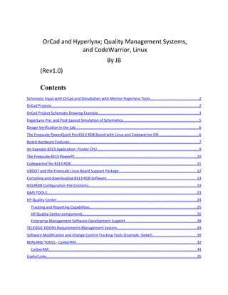
  • 10. A simple text LCD can be controlled via the GPIO interface. An external Ethernet PHY module can be used to interface the printer to a network, if required. One of the built-in USB interfaces can be used to wake up the printer upon activity. The Freescale 8313 PowerPC The 8313 RDB contains a PowerQuicII core. An 8313 block diagram is reproduced below. MPC8313E Block Diagram
  • 11. (reproduced from FS website) The e300 core has an L1 16K instruction cache and a separate L1 16K data cache. The e300 Core power is approximately 1.2W. Standby power is less than 300mW. PowerQuicII pro devices such as the 8313E include a security feature module. The processor can boot from NOR or NAND devices and includes one SPI interface and two I2C interfaces. The IC circuits include 4 DMA controllers that support I/O, and a built-in programmable interrupt controller. Codewarrior for 8313 RDB The Codewarrior RDB includes a project creation wizard that allows one to automatically include libraries with drivers for devices on the 8313RDB. Users can select C or C++ code. Freescale provides source code modules that can be edited for re-use, including main.cpp, interrupt.c, and sc_handler.c (a system call handler). After the user selects “make,” the “run” command accesses the Freescale USB tap development interface to download and begin execution of user code.
  • 12. ‘ UBOOT and the Freescale Linux Board Support Package UBOOT permits users to download files. UBOOT is loaded into the RDB DDR memory then flashed into the RDB flash memory using commands described in Freescale application note AN3947. UBOOT is configured for NFS deployment in the process, which allows networking commands to be used for the download process.
  • 13. Steps to prepare the Freescale Linux BSP (Board Support Package) include: • Download the appropriate BSP • Build the kernel • Modify the device tree files for the board rev. • Place kernel and device tree in a directory for downloading later. Additional steps before downloading the Linux kernel include using the setenv command to configure the host. Compiling and downloading 8313 RDB Software After the Linux kernel is appropriately installed, users can compile C or C++ code using Codewarrior and appropirate RDB interface drivers, make the package, and then use the “run” command to download it to the RDB. The console makes use of a serial port for user input and feedback during program operation. 8313RDB Configuration File Contents Here are the contents of the 8313RDB configuration file:
  • 14. #setMMRBaseAddr 0xFF400000 writereg MBAR 0xFF400000 # change internal MMR base from 0xff400000 (reset value) to 0xe0000000 writemem.l 0xff400000 0xe0000000 # IMMRBAR = 0xe0000000 #setMMRBaseAddr 0xe0000000 writereg MBAR 0xe0000000 #################################### ########## # System Configuration - Local Access Windows #################################### ########## # Local Bus Local Access Windows ################################# # WINDOW 0 - NOR FLASH writemem.l 0xe0000020 0xfe000000 # LBLAWBAR0 - begining at 0xfe000000 writemem.l 0xe0000024 0x80000018 # LBLAWAR0 - enable, size = 32MB # WINDOW 1 - NAND Flash
  • 15. writemem.l 0xe0000028 0xf8000000 # LBLAWBAR1 - begining at 0xf8000000 writemem.l 0xe000002c 0x80000018 # LBLAWAR1 - enable, size = 32MB # WINDOW 2 - VSC7385 writemem.l 0xe0000030 0xf0000000 # LBLAWBAR2 - begining at 0xfc100000 writemem.l 0xe0000034 0x80000010 # LBLAWAR2 - enable, size = 128kB # WINDOW 3 - Read Write Buffer writemem.l 0xe0000038 0xfa000000 # LBLAWBAR3 - begining at 0xfa000000 writemem.l 0xe000003c 0x8000000e # LBLAWAR3 - enable, size = 32kB # PCI Local Access Windows ################################# # WINDOW 0 writemem.l 0xe0000060 0x80000000 # PCILAWBAR0 - begining at 0x80000000 writemem.l 0xe0000064 0x8000001c # PCILAWAR0 - enable, size = 512MB # WINDOW 1 writemem.l 0xe0000068 0xa0000000 # PCILAWBAR1 - begining at 0xa0000000 writemem.l 0xe000006c 0x8000001c # PCILAWAR1 - enable, size = 512MB
  • 16. # DDR Local Access Windows ################################# # WINDOW 0 - 1st DDR SODIMM writemem.l 0xe00000a0 0x00000000 # DDRLAWBAR0 - begining at 0x00000000 writemem.l 0xe00000a4 0x8000001a # DDRLAWAR0 - enable, size = 128MB #********************************* # DDR2 Controller Registers #********************************* #DDRCDR writemem.l 0xE0000128 0x73000002 # DDR_SDRAM_CLK_CNTL # CLK_ADJST = b'010' ; 2 Clocks writemem.l 0xE0002130 0x02000000 # CS0_BNDS # SA0 = b'000000000000' # EA0 = b'000000000111' writemem.l 0xE0002000 0x00000007 ;# 128MB # CS0_CONFIG # CS_0_EN = b'1' # AP_0_EN = b'1'
  • 17. # ODT_RD_CFG = b'0' # ODT_WR_CFG = b'1' # BA_BITS_CS_0 = b'00' # ROW_BITS_CS_0 = b'001' ; 13 row bits # COL_BITS_CS_0 = b'010' ; 10 columns bits writemem.l 0xE0002080 0x80840102 # TIMING_CFG_3 # EXT_REFREC = b'000' ; 0 Clocks writemem.l 0xE0002100 0x00000000 # TIMING_CONFIG_1 # bit 1-3 = 2 - PRETOACT precharge activate interval 2 clock cycles # bit 4-7 = 6 - ACTTOPRE activate to precharge interval 6 clock cycles # bit 9-11 = 2 = ACTTORW activate to r/w interval 2 clock cycles # bit 13 - 15 = 5 - CASLAT CAS latency 3 clock cycles # bit 16 - 19 = 6 - REFREC refresh recovery time 14 clock cycles # bit 21 - 23 = 2 - WRREC data to precharge interval 2 clock cycles
  • 18. # bit 25 - 27 = 2 - ACTTOACT activate to activate interval 2 clock cycles # bit 29 - 31 = 2 - WRTORD write data to read command interval 2 clock cycles writemem.l 0xe0002108 0x26256222 # TIMING_CONFIG_2 # bit 19-21 = b010 - WR_DATA_DELAY - 1/2 DRAM clock delay writemem.l 0xe000210C 0x0f9028c7 # TIMING_CFG_0 # RWT = b'00' ; 0 Clocks # WRT = b'00' ; 0 Clocks # RRT = b'00' ; 0 Clocks # WWT = b'00' ; 0 Clocks # ACT_PD_EXIT = b'010' ; 2 Clocks # PRE_PD_EXIT = b'010' ; 2 Clocks # ODT_PD_EXIT = b'1000' ; 8 Clocks # MRS_CYC = b'0010' ; 2 Clocks writemem.l 0xE0002104 0x00220802 # DDR_SDRAM_CFG # MEM_EN = b'0' # SREN = b'1' # RD_EN = b'0'
  • 19. # SDRAM_TYPE = b'011' # DYN_PWR = b'0' # 32_BE = b'1' # 8_BE = b'0' # NCAP = b'0' # 2T_EN = b'0' # x32_EN = b'0' # PCHB8 = b'0' # HSE = b'0' # MEM_HALT = b'0' # BI = b'0' writemem.l 0xE0002110 0x43080000 # DDR_SDRAM_CFG_2 # FRC_SR = b'0' # DQS_CFG = b'00' # ODT_CFG = b'10' # NUM_PR = b'0001' # D_INIT = b'0' writemem.l 0xE0002114 0x00401000 # DDR_SDRAM_MODE # Extended Mode Register: Outputs=0 or 1? # Mode Register writemem.l 0xE0002118 0x44400232 # DDR_SDRAM_MODE_2 # Extended Mode Register 2 # Extended Mode Register 3 writemem.l 0xE000211C 0x8000c000
  • 20. # DDR_SDRAM_INTERVAL # REFINT = 800 Clocks # BSTOPRE = 100 Clocks writemem.l 0xE0002124 0x03200064 #delay before enable sleep 300 #Enable: DDR_SDRAM_CFG writemem.l 0xE0002110 0xc3080000 #################################### ########## # Local Bus Interface (LBIU) Configuration #################################### ########## # CS0 - 8MB NOR FLASH writemem.l 0xe0005000 0xfe001001 # BR0 base address at 0xFE000000, port size 16 bit, GPCM, valid writemem.l 0xe0005004 0xfe006ff7 # OR0 8MB flash size, 15 w.s., timing relaxed # CS1 - NAND FLASH writemem.l 0xE0005008 0xF8000C21 # BR1 base address at
  • 21. 0xF8000000, port size 8 bit, FCM, valid writemem.l 0xE000500c 0xFFFF83CC # OR1 32KB flash size, small page #for a Rev A board, please comment the line above and use the below initialization for OR1: #writemem.l 0xE000500c 0xFFFF93CC # OR1 32KB flash size, small page # CS2 - VSC7385 writemem.l 0xe0005010 0xf0000801 # BR2 base address at 0xF0000000, port size 8 bit, GPCM, valid writemem.l 0xe0005014 0xFFFE09FF # OR2 128KB # CS3 - Read Write Buffer writemem.l 0xe0005018 0xfa000801 # BR3 base address at 0xfa000000, port size 8 bit, GPCM, valid writemem.l 0xe000501c 0xFFFF8FF7 # OR3 32KB # LBCR - local bus enable writemem.l 0xe00050d0 0x00000000 # LCRR
  • 22. # bit 14 - 15 = 0b11 - EADC - 3 external address delay cycles # bit 28 - 31 = 0x0010 - CLKDIV - system clock:memory bus clock = 2 writemem.l 0xe00050d4 0x00030002 writereg MSR 0x2000 # FP available, machine check disable, exception vectors at 0x0000_0000 writemem.l 0xE0000800 0x00000000 # ACR - Enable Core writemem.l 0xfa000000 0x00000000 # write board LEDs # # NAND Flash settings # writemem.l 0xE00050E0 0x0000E000 # FMR # MRTPR - refresh timer prescaler writemem.l 0xe0005084 0x20000000 writereg SP 0xf
  • 23. QMS TOOLS In product development and test methodologies, documentation is hierarchical: • Requirements • Specifications • Test Plans Automated tools permit businesses to manage release contents for multiple products, assigning software component versions and also re-usable tests to cover the requirements for multiple products, and to assess the risks and issues (defects) in product releases. Using enterprise level tools, business planners can schedule development and testing of multiple projects more effectively by taking into account the status, defects, and tests needed for each product to plan and accomplish order (sales delivery) goals effectively.
  • 24. HP Quality Center HP Quality Center features include means to: • manage project requirements and their changes • track software development progress • Assess risk • Plan software release contents HP Quality Center capabilities are analogous to Borland Project Lifecycle Management tools. HP Quality center can be used across distributed organizations. HP Quality Center supports: • Centralized release management and version numbering of large software products across the organization. • Ability to assign versions of software components created in different groups to the builds for specific products. • Ability to assign versions of tests for software components to specific product releases, re-using existing tests and test scripts.
  • 25. • Ability to re-use tests and test scripts for different products. • Ability to keep track of bugs and defects for each product in a centralized database, based upon its specific software component versions and test script test status/results. • Risk assessment is possible for a given product release using this information. All software components have their own version numbers. Tests and Test scripts are assigned their own release and version numbers also. Tracking and Reporting Capabilities Using linked information and database analysis, HP Quality Center provides the ability to assess: • Requirements coverage by units and modules the product comprises. Defects affecting requirements are visible. • Reporting capabilities provide ways to share info • Large QA efforts can make use of these tools across a network for collaboration to succeed.
  • 26. • Workflows through the lifecycle provide standardized repeatable methods. By including tools supporting each portion of the product lifecycle, consistent, repeatable QA can be performed on software successfully. As with all development methodology tools, the ability to find defects more easily before production is a strong advantage. HP Quality Center components • The Quality Center Foundation – basic platform for workflow rules. Can be configured for your business environment. • HP TestDirector (was in v9; now part of V10 without using this name)– Used to manage requirements, plan and schedule tests (assigning test assets to requirements), reporting results, and reporting on defects and issues to facilitate planning and risk assessment.
  • 27. • Functional Test components – permit advanced automated functional testing and regression testing. A special module supports enterprise IT applications. • HP Business Process Testing software – allows business analysts and other planners to analyze business use cases of software products and the process flows involved with creating multiple products (with insight into scheduling based upon status of all tests and components). This permits scheduling of test development to proceed in a manner which facilitates success across the product line and software release roll-out for multiple products (thanks to a single large QC repository of info available). • Using HP Quality Center, one can identify and schedule tests needed to address the impact of changes, so
  • 28. application quality is increased and risk is minimized. Enterprise Management Software Development Support  HP Quality Center can make use of SAP and SOA extensions to support SAP, SOA, and Oracle® quality management.  As with all software developed using HP Quality Center, one can identify and schedule tests needed to address the impact of changes, so application quality is increased and risk is minimized.  HP Service Test components – An advanced quality management package, covering SOA test management, requirements, defects tracking, functional testing, regression testing and business process design validation.
  • 29. TELEOGIC DOORS Requirements Management System Teleogic Doors uses a database with linked, numbered sections for each product development milestone document; e.g. Market requirements, Engineering system requirements, hardware and software unit specifications, and test plan test cases. Each are numbered and linked together. With doors, one can verify that a test case covers or “traces” back to each requirement or specification above. One can also verify which section of specifications documents cover product system level requirements. (the name “Doors” refers to the ability to jump or link between project hierarchical documents). This tool was introduced in the late 1990’s. It is best for product development and checking traceability of hierarchical documents.
  • 30. Software Modification and Change Control Tracking Tools (Example: Siebel) Tools in this category assist system developers by keeping track of software change requests and their status. Siebel is an example of a basic MR tracking tools. Siebel allows users to conveniently enter MR’s, assign priorities, and owners. A project team member is assigned as MR change control administrator/tracker. MR’s pass through a series of steps that are user definable, and may include: Open (by originator) • UI (owner) • Fixed (new owner is tester) • Verified (owner • Closed (MR admin) Other MR assignments might include: • Defer
  • 31. In the case of defer, the project team leadership decides which release to phase changes into. Useful information catalogued with entries in software change control databases include: • Description of problem • How to reproduce problem • Area impacted (as specific as possible; a software module) • Severity (critical, high, medium, low; or 1-4) – Critical changes require prompt investigation. • Impact of problem: who is affected where • Customer who reported problem and notes about their needs. Siebel and other MR tracking tools allow users to print reports sorted by severity, status (open, UI, etc), and other fields. As change control tracking on PBX and large ATM switch projects at Bell Labs and ViaGate Technologies, I used tools to track MR status and priorities. As senior systems engineer in the software development group at ViaGate, I was responsible for planning software release
  • 32. contents for a period of time early in the initial product shipment timeframe. This involved working with engineers, marketing and engineering management closely to evaluate status and make decisions about release contents for our ATM switch. The ViaGate switch used 12 unix multiprocessing boards, and provided internet, video (CATV lineup), and VLAN access to up to 240 subscribers using set top boxes and VDSL modems. The switch was designed for use in basements, and connected to the telco by Sonet fibers. ViaGate Product Description (Telecommunication Switch for Internet, VLAN, and Video Access to 240 Subscribers) http://www.jbmsee.net/reslib/ViaGateNode.ht m BORLAND TOOLS - CaliberRM Borland makes leading Windows software compiler IDE tools in competition with Microsoft.
  • 33. Borland has entered the market with software lifecycle management tools. Tools include these aspects of development: • Requirements definition and management • Testing, software release planning, and risk assesment Borland’s testing and ASQ tools help automate planning/tracking in these areas: • Requirements based testing • Software Test Management (planning, documentation of test processes) • Software Development Metrics – to assist managers • Test Automation – tools to help automate developer (unit), functional (system and integration testing), and performance testing (product quality/verification). This is accomplished by tools that support each step in the workflow.
  • 34. (from Borland site) CaliberRM During the fall of 2003, I attended a training and info seminar on Borland compilers and software development project tools. These tools assist requirements traceability, change tracking, release planning, and risk assessment. Borland has attempted to provide tools for each essential workflow step, allowing project managers to track status of large projects in an organization. The CaliberRM tools is used for requirements management, and provides network based means to collaborate between users on large projects. CaliberRM allows users to enter detailed info about unit modules and their development status.
  • 35. Borland also HP Quality Center components (The “Quality Center Foundation, “ HP TestDirector for HP Quality Center, and Extensions for SAP and SOA) Useful Links Doors http://www.wbbinc.com/doors_requirements_ management.html HP Quality Center http://h50281.www5.hp.com/software/index.ht ml Borland Project Management Tools http://www.borland.com/us/solutions/requirem ents-definition-management/index.html (copyright)