Level limit switch-Soliswitch FTE30
•
1 recomendación•1,273 vistas

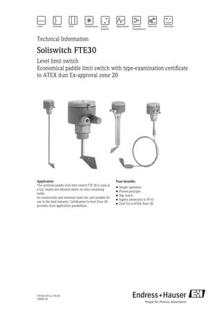
The universal paddle level limit switch FTE 30 is used as a full, empty and demand alarm on silos containing solids. Email: lam.nguyen@vietan-enviro.com HP: 0945 293292

Recomendados
Más contenido relacionado
Similar a Level limit switch-Soliswitch FTE30
Similar a Level limit switch-Soliswitch FTE30 (20)
Más de Edress Hauser: Flow Meter, Level, Pressure, Temperature
Más de Edress Hauser: Flow Meter, Level, Pressure, Temperature (20)
Último
Último (20)
Level limit switch-Soliswitch FTE30
- 1. TI052R/09/en/06.08 50080138 Technical Information Soliswitch FTE30 Level limit switch Economical paddle limit switch with type-examination certificate to ATEX dust Ex-approval zone 20 Application The universal paddle level limit switch FTE 30 is used as a full, empty and demand alarm on silos containing solids. Its construction and materials make the unit suitable for use in the food industry. Certification to dust Zone 20 provides more application possibilities. Your benefits • Simple operation • Proven principle • Slip clutch • Ingress protection to IP 65 • Dust Ex to ATEX Zone 20
- 2. FTE30 2 Endress+Hauser Function and system design Measuring principle Fig. 1: Level measurement changeover contact The shaft and paddle are driven via a reduction gear by a synchronous motor. If the paddle is stopped by material covering it, the hinged motor in the housing moves from the rest to the switched position. This movement operates two switch contacts. The first is for external level indication and the second switches power off the motor. The paddle starts to rotate once the level falls below the paddle level. The hinged motor returns to its rest position and the two contacts switch to the normal operation condition. Intermittent loads that operate against or even in the direction of rotation are evened out by using a slip clutch. Measuring system Complete level limit switch consisting of a shaft with synchronous motor and slip clutch, single pole changeover contact. Typical application areas for level detection are: Cereals, Sugar, Cacao, Animal feeds, Washing powders, Chalk, Dry plaster, Cement, Granulates, Wood chips Input Measured variable Filling height of solids Measuring range Variable dependent on the model used by: • Installation position • Length of the rotating shaft/rope Output Output signal A contact changes once the solids reach the level limit. Switching output Potential free change over contact. Connectable Load • Relay: ≤ 250 VAC, nominal current 100 mA...10 A, on motor load ≤ 3 A • PLC-relay: ≤ 48 VDC, nominal current10 mA...100 mA Switch time delay approx. 2 seconds Mechanical life time min. 500 000 switch cycles
- 3. FTE30 Endress+Hauser 3 Power supply Electrical connection Supply voltage • 230 VAC 50/60 Hz, ± 10% max. 4.5 VA • 115 VAC 50/60 Hz, ± 10% max. 4.5 VA • 48 VAC 50/60 Hz, ± 10% max. 4.5 VA • 24 VAC 50/60 Hz, ± 10% max. 4.5 VA • 20 to 28 VDC, Imax = 66 mA Cable entry Cable entries PG 13.5 Installation condition Installation instructions Orientation Fig. 3: Installation orientations of the device, dimensions in mm (inch) Fig. 2: Terminal layout • PE: Earth (Ground)connection • N (AC), - (DC): Power connection • L (AC), + (DC): Power connection • 41: Normally closed contact • 42: Common • 43: Normally open contact Correct installation: Incorrect installation: Vertically from top of silo (Pos. a) In direction of solids flow (Pos. e) Angled from the top (Pos. b) Installation coupling too long (Pos. f) From the side (Pos. c) Horizontally with shaft length > 300 mm (11.81"); not valid for version with strengthened shaft (Pos. g) With protective cover against falling solids (Pos. d) Angled from below (Pos. h)
- 4. FTE30 4 Endress+Hauser Mechanical load on the shaft • max. 60 N • max. 1500 N on strengthened shaft Load on the rope max. 1500 N Operating pressure (abs.) 0.5 to 1.8 bar (7.25 to 26.1 PSI) Environmental conditions Ambient temperature range - 20 °C to + 60 °C (-4 to 140 °F) Storage temperature - 20 °C to + 60 °C (-4 to 140 °F) Degree of protection • IP 65 with closed lid • IP 20 with open lid Vibration resistance IEC 654-3, dimension V.S.1 (v<3 mm/s, 1<f<150 Hz) Protection class I Measurement category II Pollution degree 2 Altitude Up to 2000 m (6560 ft) above sea level. Process conditions Medium temperature range -20 °C to +80 °C (-4 to 176 °F) Solids weight 100 g/l Material grain size Up to 50 mm (1.97")
- 5. FTE30 Endress+Hauser 5 Mechanical construction Design, dimensions Fig. 4: Dimensions FTE30 in mm (inch) Pos. A: Solid shaft Pos. B: Rope extension Pos. C: FTE30 with hinged paddle as additional equipment or as retrofit kit Hinged paddle (optional) The paddle is hinged so that it can be easily mounted through a threaded mounting coupling. The paddle returns to its normal operating position by means of a built-in spring.Removal of the unit is always possible.The hinged paddle can be mounted to both the solid shaft as well as the rope extended versions. Protective cover (optional) When installing the device, the protective cover can simply be mounted at the same time. It protects the device in outdoor use against extreme climatic conditions, e.g. hailstorm when used on the roof of a silo. Weight Compact version approx. 1 kg (2.2 lb) Compact version Extended version Strengthened version Rope extension Shaft length X Shaft length X Shaft length X Rope length of approx. 2000 mm (78.74"), can be shortened 75 mm (2.95") 100 mm (3.94") 300 mm (11.81") 200 mm (7.87") 500 mm (19.7") 300 mm (11.81") 800 mm (23.6") 400 mm (15.75") 500 mm (19.7") 600 mm (23.6")
- 6. FTE30 6 Endress+Hauser Material • Housing, lid and process connection: plastic with 30% fibre glass. • Shaft: Stainless steel 1.4305 • Paddle: Stainless steel 1.4301 • O-ring seal: NBR • Shaft seal: NBR Perbunan • Cable entries PG 13.5: for cable diameter 7.0 to 11 mm (0.28 to 0.43") poliamid with neoprene-CR seal • As option: – Process connection: Stainless steel 1.4305 – Rope extension: Stainless steel 1.4401 with stainless steel 1.4305 weight – Hinged paddle: Stainless steel 1.4435 – Protection tube: Stainless steel 1.4301 – Protective cover: Stainless steel 1.4301 Shaft bearing High power friction bearing - maintenance free Shaft rotation approx. 1 rotation per minute Process connection Threaded boss - thread G1 ½" Terminals Plug in screw terminals 2.5 mm2 (14 AWG) solid core, 1.5 mm2 (16 AWG) core with ferrule Human interface Display elements signal lamp (optional) Yellow signal lamp illuminates in alarm condition (shaft stopped). The signal lamp is fitted in the PG cable gland. It indicates the switch condition of the unit: • Signal lamp on: Contact 42-43 closed • Signal lamp off: Contact 41-42 closed Fig. 5: Signal lamp as option Certificates and approvals CE approval The measurement system fulfils the requirements demanded by the EU regulations. Endress+Hauser acknowledges successful unit testing by adding the CE mark. Ex approval Dust Ex Zone 20 Construction certification II 1/3 D Zone 20/22
- 7. FTE30 Endress+Hauser 7 Ordering information This ordering information can give an overview about the available order options. The Endress +Hauser sales organization can provide detailed ordering information and information on the order code. Soliswitch FTE30 Power supply; Output: A 230 V AC, relay 250 V AC, 100 mA...10 A B 115 V AC, relay 250 V AC, 100 mA...10 A C 48 V AC, relay 250 V AC, 100 mA...10 A D 24 V AC, relay 250 V AC, 100 mA...10 A E 20 to 28 V DC, relay 250 V AC, 100 mA...10 A F 230 V AC, PLC-Relay 48 V DC, 10 mA...100 mA G 115 V AC, PLC-Relay 48 V DC, 10 mA...100 mA H 48 V AC, PLC-Relay 48 V DC, 10 mA...100 mA I 24 V AC, PLC-Relay 48 V DC, 10 mA...100 mA J 20 to 28 V DC, PLC-Relay 48 V DC, 10 mA...100 mA K 230 V AC, paddle revolution 6 U/min; 100 mA...10 A L 20 to 28 V DC, paddle revolution 6 U/min; 100 mA...10 A M 230 V AC, paddle revolution 6 U/min; 10 mA...100 mA relay 250 V AC N 20 to 28 V DC, paddle revolution 6 U/min; 10 mA...100 mA relay 250 V AC Y Special version Process connection: A Thread G 1½, PBT B Thread G 1½, 303 C Thread G 1½, 303, armoured Y Special version Version: A Shaft 100 mm B Shaft 200 mm C Shaft 300 mm D Shaft 400 mm E Shaft 500 mm F Shaft 600 mm G Shaft 120 mm 1 Shaft 75 mm; compact 2 Rope 2 m, 316, shortable 3 Shaft 300 mm; armoured 4 Shaft 500 mm; armoured 5 Shaft 800 mm; armoured 9 Special version Paddle; Additional option: 1 303; w/o signal lamp 2 303; signal lamp 3 316L; fold-away 4 316L; fold-away; signal lamp 9 Special version FTE30- ⇐ Ordercode
- 8. FTE30 Accessories Documentation Short operating instructions Level Limit Switch FTE30 (KA059R/09/a6) Accessory Order No. Hinged paddle retro-fit kit 50089768 Protective cover, dimensions in mm (inch) 51005551 Rope extension 2 m (78.74") 50080209 Instruments International Endress+Hauser Instruments International AG Kaegenstrasse 2 4153 Reinach Switzerland Tel. +41 61 715 81 00 Fax +41 61 715 25 00 www.endress.com info@ii.endress.com TI052R/09/en/06.08 50080138 FM+SGML 6.0