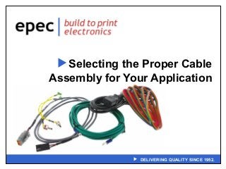
Selecting the Proper Cable Assembly for Your Application Webinar
•Download as PPT, PDF•
1 like•1,098 views

This webinar will concentrate on the electrical and physical considerations for cable assemblies. An area of focus will be on cable assembly performance criteria of conductors and insulators to help distinguish the best combination for meeting required performance levels. Safety certifications and connector performance for various applications will also be reviewed. As well as determining the best combination of physical and electrical performance for an application without over designing and over-pricing your assembly.

Recommended
Recommended
More Related Content
More from Epec Engineered Technologies
More from Epec Engineered Technologies (20)
Recently uploaded
Recently uploaded (20)
Selecting the Proper Cable Assembly for Your Application Webinar
- 1. DELIVERING QUALITY SINCE 1952. Selecting the Proper Cable Assembly for Your Application
- 2. 2 Installation Environment Is This A Static Or A Dynamic Installation? Flexible vs. Flexible – There Is A difference • Flexible = Easily Routed During Installation • Flexible = Able to Withstand Continuous Movement – Cable Design Impacts Both Flexible and Flexible • Conductor Strand Count = More Strands = Improved Flexibility = Higher Cost • Flexible Insulations = Improve Flexibility = Softer Compounds = Flammability Concerns/ Easily Compromised • Tapes – Woven (Paper) vs. PTFE – PTFE Provides More Flexibility at a Higher Cost • Outer Sheath Application – Material Selection – Application Method Tube-On vs. Pressure
- 3. 3 Installation Environment Is The Assembly Going To Be Used In Harsh Environments? – Industrial • Oil, Water, Fluid Resistant • Crush Proof – Medical • Autoclavable • Intrusive • Patient Contact • Triboelectric Noise – Datacomm/Telecomm • UV Resistant • Exposure to Elements What Type Of Signal Will The Assembly Be Exposed To? – Power – Low voltage – High Frequency
- 4. 4 Safety Authorities What Safety Certifications Will Be Needed For The Installation? – NEC (National Electric Code) • “Recommended Standard” – Becomes law when officially adopted by state or local governments – Local inspector has responsibility of enforcing – UL (Underwriters Laboratories) • Safety Consulting and Certification • Tests cables and components to set standards – CSA (Canadian Standards Association) • Develops standards that enhance public safety • Test cables and components to set standards – ETL (Intertek Testing Services) • Electrical performance and reliability testing service
- 5. 5 Cable Strain Relief Is A Strain Relief Needed To Protect The Assembly? – Provides transition point from cable to connector or connection point – Prevents load applied to cable from being transferred to terminations • Point of termination most likely point of failure in applications needing flexibility • Well designed strain relief will isolate termination points – Strain Relief Available as pre-manufactured or over-molded designs
- 6. 6 Cable Strain Relief What are The Types Of Strain Reliefs? – Pre-manufactured • Typically slipped on cable before connector is terminated • Glued or screwed onto the connector assembly • Most off-the-shelf connectors have corresponding strain reliefs – Over-molded • Superior flex life • Increased tensile strength • Increased moisture protection • Design may include strain relief and grommet – Designed to be captured and held in place by opening in enclosure
- 7. 7 Cable Strain Relief Over-molded Strain Reliefs Should Bond to Cable Outer Insulation and Connector Body – Increases tensile strength – Increases moisture resistance Strain Reliefs Available In Solid/Smooth or Segmented – Smooth design less flexible but easier to clean • Ideal for environments such as Medical applications – Segmented design uses spaces and walls • Provides greatest amount of bend relief • Segment closest to termination point closes first • Segment furthest away from termination point closes last
- 8. 8 Cable Strain Relief Strain Reliefs Designed to Flex As Unidirectional or Multidirectional – Cable design limits flexibility • Ribbon cable, bonded cable, lamp/power cord Length of Strain Relief Contributes to Performance – Longer strain reliefs more effective
- 9. 9 Assembly Shielding Concerns Does The Assembly Need To Be Shielded To Control EMI/RFI? – Types of Shielding • Foil Shield – Low cost – Ease of termination – Good flexibility – Excellent at high frequencies, less effective at low frequencies – Short flex life • Braid Shield – Higher cost – More difficult to terminate – Best at low frequencies – Increased flex life • Spiral Shield – Excellent flexibility – Long flex life – Poor at high frequencies – Difficult to terminate • Foil and Braid Shield – Best at all frequencies – Ease of Termination – Highest Cost
- 10. 10 Assembly Electrical Performance What Electrical Performance Issues Might Need To Be Addressed? – Ampacity – Maximum Current Rating • Conductor Size • Circuit length – Attenuation – Signal Reduction • Conductor size • Conductor material • Insulation material – Cross-talk – Signal From One Component Effects Another Component • Pair twist • Shielding of pairs – High Frequency = Silver Plated Copper • Silver conductivity better than copper • Skin effect – High Frequency = High Performance Compounds • Foamed dielectrics
- 11. 11 Connector Choices What Methods Are Used To Attach Cables To Connectors? – Crimp • Connection achieved using solderless electrical connector • Mechanically deformed / compressed (crimped) tightly around the wire – Push/Press • No tools required – Solder • Utilizes Solder Cup, Solder Eyelet, Solder Hook, or Solder Tail for connection – IDC (Insulation Displacement Connector) • Connection process which forces a selectively sharpened blade or blades through the insulation of a wire, bypassing the need to strip the wire of insulation before connecting
- 12. 12 Assembly Choices – Environment Concerns • Vibration or Movement – Locking Connectors • Exposure to Fluids – Sealed Connectors – Performance Concerns • Industry Standards – HDMI – SFP+ – QSFP – Etc. What Are The Main Issues To Be Concerned With?
- 13. 13 Summary Many Options Available For Specific Installations – Cable – Connectors – Strain Relief Type Of Signal and Installation Environment Drives ALL Options – Cable – Termination Method – Connector Type Epec can work with you to design and build an assembly that is suitable for you specific application and exceeds your expectations.
- 14. 14 Our Products Battery Packs Flex & Rigid-Flex PCB’s User Interfaces Fans & Motors Cable Assemblies Printed Circuit Boards
- 15. 15 Design Centers & Technical Support Battery Pack & Power Management – Denver, CO User Interfaces – Largo, FL Fans & Motors – Wales, UK PCB’s – New Bedford, MA & Shenzhen, China Flex & Rigid Flex – Toronto, Canada Cable Assemblies – New Bedford, MA Our Engineering and Design teams are ready to help our customers create world class and cost effective product solutions.
- 16. 16 Q&A Questions? – Enter any questions you may have in the Control Panel. – If we don’t have time to get to it, we will reply via email.
- 17. 17 Thank You Check out our previous webinars at www.epectec.com. For more information email sales@epectec.com. Stay Connected with Epec Engineered Technologies Follow us on our social media sites for continuous technical updates and information: