SlideShare una empresa de Scribd logo
1 de 5
Wiring
Finally, some meat... I spent an entire day hand twisting 18ga stranded wire into 8' long
pairs with various colors. Right side channels use Red as the (+) side, Left side channels
use Blue. I created custom RCA cables and wired the amp to crossovers, crossovers to
wiring harness, using the hand-rolled twisted pairs. It was a tough job that gave me 7
blisters on my two hands, but it was worth it! My system has absolutely no noise, no
interference, and it looks great. Twisted pair is the best choice for the car. Just look at
what BMW used - twisted pair all over the place.

I wired the power for the amp directly from the battery using 8ga Monster Cable power
wire. Thanks BMW for putting the battery in the trunk! This was a very easy job. I ran
the wiring from the battery compartment, along the other two monster sized cables under
the right trim panel in the trunk, and up under the deck to the amp. The ground wire is
short and sheet-metal screwed to the underside of the rear deck. Be sure to use the same
guage wire for both power and ground. This minimizes noise.


Pin-Outs
Here is the detail of the wiring connections I used. Please note that I only used a subset of
the available pins because the factory system has 10 individual loudspeakers. My system
effectively has 6 since the rear speakers are coaxial. This leaves the 2 front midrange
drivers and the 2 rear tweeters disconnected and unused. I also wired the rear speakers
directly from the crossovers, which leaves the rear woofer connections to the harness
unused as well.

12-pin Connector
This is the baby that delayed my project completion. No aftermarket companies make
wiring harness interface connectors for the E39. All of my research showed that they may
be coming out with them, but didn't have them now. So, it was up to me to make my own.
I contacted Amp in Germany to get a matching male connector to interface with the
female connector on the factory harness. Even in Silicon Valley I could not find a
suitable connector for this job. So, I was on my own! After coming up empty, my
colleague Sherman informed me that it's possible to get "samples" from component
manufactures. So, I called Amp (see references section for contact info) and spoke with
the designer of the part in the car. He gave me the part number for the matching
connector and I ordered some samples. I did mention I needed the pins as well and
assumed they'd be shipped with the connector, but with my luck they didn't arrive.
Another call, another conversation, and the pins were on the way.

Connections I used
One thing I have to tell you is I'm colorblind. So, referring to the colors on the wires is
not an option for me. I had a friend map the positions for me so I could do this without
assistance. I provide the info I got from Willard Lee for your reference only. Be sure to
double check all connections before you go with them. I used a digital voltmeter (DVM)
with a tone setting to identify each speaker wire.


                               1     2    3    4     5    6

                               12   11   10          8    7


                                    Pin Colors Used

                           Yellow/Red Left Front Woofer (-)
                      1

                           Yellow/Brown Left Front Woofer (+)
                      2

                           Blue/Red Right Front Woofer (-)
                      3

                           Blue/Brown Right Front Woofer (+)
                      4

                           Yellow/Purple Left Rear Woofer (+)
                      5

                           Yellow/Grey Left Rear Woofer (-)
                      6

                           Blue/Grey Right Rear Woofer (-)
                      7

                           Blue/Purple Right Rear Woofer (+)
                      8

                           Blank
                      9
Brown Ground (DO NOT USE)
                          10

                                   White Remote Turn On Lead
                          11

                                   Red Power (DO NOT USE)
                          12


26-pin Connector
This was a little tricky. I manufactured my own 26 pin connector using the above
mentioned 26-pin shrouded header. The pins are so close together that I had to solder on
6" solid core wire leads, then connect the stranded pairs to these leads. You're in for a
treat doing this part. Use a pencil point soldering iron, isolate the bottom row of pins
from the top row with something, and be sure to use shrink tubing around each individual
connection to insulate them from eachother. I suggest buying a few extras in case you
mess up. Also, be sure no solder dripped and connected two or more pins together. That
would be really bad!

When connecting RCA plugs to the harness remember that the center post on the RCA
plug is the positive lead from the harness.


             1        2        3     4                8   9    10 11    12   13

             26       25 24         23               19 18     17 16    15   14


                                          Pin Colors Used

                          Brown/Orange Head Unit Right Rear Output (-)
                  1

                          Blue/Black Head Unit Right Rear Output (+)
                  2

                          Yellow/Black Head Unit Left Rear Output (+)
                  3

                          Brown/Orange Head Unit Left Rear Output (-)
                  4

                  5

                  6
7

     Blue/White Right Front Mid (+)
8

     Blue/Orange Right Front Mid (-)
9

     Yellow/Black Left Rear Tweeter (+)
10

     Yellow/Grey Left Rear Tweeter (-)
11

     Blue/Black Right Rear Tweeter (+)
12

     Blue/Grey Right Rear Tweeter (-)
13

     Yellow/Brown Left Front Mid (-)
14

     Yellow/White Left Front Mid (+)
15

     Blue/Brown Right Front Tweeter (-)
16

     Blue/Green Right Front Tweeter (+)
17

     Yellow/Brown Left Front Tweeter (-)
18

     Yellow/Green Left Front Tweeter (+)
19

20

21

22

     Brown/Orange Head Unit Right Front Output (-)
23

     Yellow/Red Head Unit Right Front Output (+)
24

     Blue/Red Head Unit Left Front Output (+)
25
Brown/Orange Head Unit Left Front Output (-)
26

Más contenido relacionado

La actualidad más candente

VW 9A engine wiring diagram
VW 9A engine wiring diagramVW 9A engine wiring diagram
VW 9A engine wiring diagramvwmaster
 
Isuzu diesel-engine-4 ja1-and-4jb1
Isuzu diesel-engine-4 ja1-and-4jb1Isuzu diesel-engine-4 ja1-and-4jb1
Isuzu diesel-engine-4 ja1-and-4jb1Yoga Ariant
 
Fusca 1300 esquema elétrico
Fusca 1300 esquema elétricoFusca 1300 esquema elétrico
Fusca 1300 esquema elétricoZemiro Bentox
 
VW Passat B6 3C 2005-... Fuses Overview
VW Passat B6 3C 2005-... Fuses OverviewVW Passat B6 3C 2005-... Fuses Overview
VW Passat B6 3C 2005-... Fuses Overviewvwmaster
 
YALE B875 GLP050VX LIFT TRUCK Service Repair Manual
YALE B875 GLP050VX LIFT TRUCK Service Repair ManualYALE B875 GLP050VX LIFT TRUCK Service Repair Manual
YALE B875 GLP050VX LIFT TRUCK Service Repair Manualnmsuemdm
 
JCB 526S Telescopic Handler Service Repair Manual SN:1182000 Onwards
JCB 526S Telescopic Handler Service Repair Manual SN:1182000 OnwardsJCB 526S Telescopic Handler Service Repair Manual SN:1182000 Onwards
JCB 526S Telescopic Handler Service Repair Manual SN:1182000 Onwardsfjsekkdmmem
 
Caterpillar cat 320 c ln excavator (prefix bbl) service repair manual (bbl000...
Caterpillar cat 320 c ln excavator (prefix bbl) service repair manual (bbl000...Caterpillar cat 320 c ln excavator (prefix bbl) service repair manual (bbl000...
Caterpillar cat 320 c ln excavator (prefix bbl) service repair manual (bbl000...fusjfjsekemwer
 
VOLVO EC460B LC EC460BLC EXCAVATOR Service Repair Manual
VOLVO EC460B LC EC460BLC EXCAVATOR Service Repair ManualVOLVO EC460B LC EC460BLC EXCAVATOR Service Repair Manual
VOLVO EC460B LC EC460BLC EXCAVATOR Service Repair Manualfujdfjjskrtekme
 
Caterpillar cat c11 industrial engine (prefix gls) service repair manual (gls...
Caterpillar cat c11 industrial engine (prefix gls) service repair manual (gls...Caterpillar cat c11 industrial engine (prefix gls) service repair manual (gls...
Caterpillar cat c11 industrial engine (prefix gls) service repair manual (gls...fjjskmdmem
 
Valtra Valmet 6850 TRACTOR Service Repair Manual
Valtra Valmet 6850 TRACTOR Service Repair ManualValtra Valmet 6850 TRACTOR Service Repair Manual
Valtra Valmet 6850 TRACTOR Service Repair Manualjkdjksmde
 
CASE 580 Super M Series 2 Backhoe Loader Parts Catalogue Manual
CASE 580 Super M Series 2 Backhoe Loader Parts Catalogue ManualCASE 580 Super M Series 2 Backhoe Loader Parts Catalogue Manual
CASE 580 Super M Series 2 Backhoe Loader Parts Catalogue Manualfjskedmme
 
Bobcat S175 S185 Skid Steer Loader Parts Catalogue Manual S/N 5190 28001 & Above
Bobcat S175 S185 Skid Steer Loader Parts Catalogue Manual S/N 5190 28001 & AboveBobcat S175 S185 Skid Steer Loader Parts Catalogue Manual S/N 5190 28001 & Above
Bobcat S175 S185 Skid Steer Loader Parts Catalogue Manual S/N 5190 28001 & Abovehdjksmemm
 
Volkswagen 1-8-turbo-aph-engine-technical-manual-spanish
Volkswagen 1-8-turbo-aph-engine-technical-manual-spanishVolkswagen 1-8-turbo-aph-engine-technical-manual-spanish
Volkswagen 1-8-turbo-aph-engine-technical-manual-spanishBuscando TRABAJO
 
Caterpillar cat m315 excavator (prefix 7 ml) service repair manual (7ml00860 ...
Caterpillar cat m315 excavator (prefix 7 ml) service repair manual (7ml00860 ...Caterpillar cat m315 excavator (prefix 7 ml) service repair manual (7ml00860 ...
Caterpillar cat m315 excavator (prefix 7 ml) service repair manual (7ml00860 ...fjjseksxckmdme
 
JCB 540-140 TELESCOPIC HANDLER Service Repair Manual
JCB 540-140 TELESCOPIC HANDLER Service Repair ManualJCB 540-140 TELESCOPIC HANDLER Service Repair Manual
JCB 540-140 TELESCOPIC HANDLER Service Repair Manualfusejjjsekfkem
 

La actualidad más candente (20)

Cat jm2960 por
Cat jm2960   porCat jm2960   por
Cat jm2960 por
 
VW 9A engine wiring diagram
VW 9A engine wiring diagramVW 9A engine wiring diagram
VW 9A engine wiring diagram
 
Isuzu diesel-engine-4 ja1-and-4jb1
Isuzu diesel-engine-4 ja1-and-4jb1Isuzu diesel-engine-4 ja1-and-4jb1
Isuzu diesel-engine-4 ja1-and-4jb1
 
Fusca 1300 esquema elétrico
Fusca 1300 esquema elétricoFusca 1300 esquema elétrico
Fusca 1300 esquema elétrico
 
VW Passat B6 3C 2005-... Fuses Overview
VW Passat B6 3C 2005-... Fuses OverviewVW Passat B6 3C 2005-... Fuses Overview
VW Passat B6 3C 2005-... Fuses Overview
 
YALE B875 GLP050VX LIFT TRUCK Service Repair Manual
YALE B875 GLP050VX LIFT TRUCK Service Repair ManualYALE B875 GLP050VX LIFT TRUCK Service Repair Manual
YALE B875 GLP050VX LIFT TRUCK Service Repair Manual
 
JCB 526S Telescopic Handler Service Repair Manual SN:1182000 Onwards
JCB 526S Telescopic Handler Service Repair Manual SN:1182000 OnwardsJCB 526S Telescopic Handler Service Repair Manual SN:1182000 Onwards
JCB 526S Telescopic Handler Service Repair Manual SN:1182000 Onwards
 
Caterpillar cat 320 c ln excavator (prefix bbl) service repair manual (bbl000...
Caterpillar cat 320 c ln excavator (prefix bbl) service repair manual (bbl000...Caterpillar cat 320 c ln excavator (prefix bbl) service repair manual (bbl000...
Caterpillar cat 320 c ln excavator (prefix bbl) service repair manual (bbl000...
 
VOLVO EC460B LC EC460BLC EXCAVATOR Service Repair Manual
VOLVO EC460B LC EC460BLC EXCAVATOR Service Repair ManualVOLVO EC460B LC EC460BLC EXCAVATOR Service Repair Manual
VOLVO EC460B LC EC460BLC EXCAVATOR Service Repair Manual
 
DIAGRAMA ELECTRICO DEL MOTOR
DIAGRAMA ELECTRICO DEL MOTOR DIAGRAMA ELECTRICO DEL MOTOR
DIAGRAMA ELECTRICO DEL MOTOR
 
Caterpillar cat c11 industrial engine (prefix gls) service repair manual (gls...
Caterpillar cat c11 industrial engine (prefix gls) service repair manual (gls...Caterpillar cat c11 industrial engine (prefix gls) service repair manual (gls...
Caterpillar cat c11 industrial engine (prefix gls) service repair manual (gls...
 
Valtra Valmet 6850 TRACTOR Service Repair Manual
Valtra Valmet 6850 TRACTOR Service Repair ManualValtra Valmet 6850 TRACTOR Service Repair Manual
Valtra Valmet 6850 TRACTOR Service Repair Manual
 
NGK
NGKNGK
NGK
 
Howo sinotruk Wiring Diagrams
Howo sinotruk Wiring DiagramsHowo sinotruk Wiring Diagrams
Howo sinotruk Wiring Diagrams
 
howo electrical system.pptx
howo electrical system.pptxhowo electrical system.pptx
howo electrical system.pptx
 
CASE 580 Super M Series 2 Backhoe Loader Parts Catalogue Manual
CASE 580 Super M Series 2 Backhoe Loader Parts Catalogue ManualCASE 580 Super M Series 2 Backhoe Loader Parts Catalogue Manual
CASE 580 Super M Series 2 Backhoe Loader Parts Catalogue Manual
 
Bobcat S175 S185 Skid Steer Loader Parts Catalogue Manual S/N 5190 28001 & Above
Bobcat S175 S185 Skid Steer Loader Parts Catalogue Manual S/N 5190 28001 & AboveBobcat S175 S185 Skid Steer Loader Parts Catalogue Manual S/N 5190 28001 & Above
Bobcat S175 S185 Skid Steer Loader Parts Catalogue Manual S/N 5190 28001 & Above
 
Volkswagen 1-8-turbo-aph-engine-technical-manual-spanish
Volkswagen 1-8-turbo-aph-engine-technical-manual-spanishVolkswagen 1-8-turbo-aph-engine-technical-manual-spanish
Volkswagen 1-8-turbo-aph-engine-technical-manual-spanish
 
Caterpillar cat m315 excavator (prefix 7 ml) service repair manual (7ml00860 ...
Caterpillar cat m315 excavator (prefix 7 ml) service repair manual (7ml00860 ...Caterpillar cat m315 excavator (prefix 7 ml) service repair manual (7ml00860 ...
Caterpillar cat m315 excavator (prefix 7 ml) service repair manual (7ml00860 ...
 
JCB 540-140 TELESCOPIC HANDLER Service Repair Manual
JCB 540-140 TELESCOPIC HANDLER Service Repair ManualJCB 540-140 TELESCOPIC HANDLER Service Repair Manual
JCB 540-140 TELESCOPIC HANDLER Service Repair Manual
 

Más de Fajar Isnanto

Micro controller based projects
Micro controller based projectsMicro controller based projects
Micro controller based projectsFajar Isnanto
 
Toyota motor manual 2 lt
Toyota motor manual 2 ltToyota motor manual 2 lt
Toyota motor manual 2 ltFajar Isnanto
 
L 2l 2l-t_repair_manual
L 2l 2l-t_repair_manualL 2l 2l-t_repair_manual
L 2l 2l-t_repair_manualFajar Isnanto
 
2010.06 defender my07 workshop manual complete
2010.06 defender my07 workshop manual complete2010.06 defender my07 workshop manual complete
2010.06 defender my07 workshop manual completeFajar Isnanto
 
Bmw e39 door lock actuator replacement
Bmw e39 door lock actuator replacementBmw e39 door lock actuator replacement
Bmw e39 door lock actuator replacementFajar Isnanto
 
Land rover monthly 2013 04
Land rover monthly 2013 04Land rover monthly 2013 04
Land rover monthly 2013 04Fajar Isnanto
 
Land rover defender_110_en_gb
Land rover defender_110_en_gbLand rover defender_110_en_gb
Land rover defender_110_en_gbFajar Isnanto
 
Series iii optional_parts_catalogue_1
Series iii optional_parts_catalogue_1Series iii optional_parts_catalogue_1
Series iii optional_parts_catalogue_1Fajar Isnanto
 
Lr series iii part 1
Lr series iii  part 1Lr series iii  part 1
Lr series iii part 1Fajar Isnanto
 
Land rover defender_110_en_gb
Land rover defender_110_en_gbLand rover defender_110_en_gb
Land rover defender_110_en_gbFajar Isnanto
 
Def 90 110_wsm_book1
Def 90 110_wsm_book1Def 90 110_wsm_book1
Def 90 110_wsm_book1Fajar Isnanto
 
Venus ecu user manual ver2.2.4.0
Venus ecu user manual ver2.2.4.0Venus ecu user manual ver2.2.4.0
Venus ecu user manual ver2.2.4.0Fajar Isnanto
 
2011 auto meter hp catalog w links
2011 auto meter hp catalog w  links2011 auto meter hp catalog w  links
2011 auto meter hp catalog w linksFajar Isnanto
 
Apt presso good to learn
Apt presso   good to learnApt presso   good to learn
Apt presso good to learnFajar Isnanto
 
Know your-differential-ec-12.97
Know your-differential-ec-12.97Know your-differential-ec-12.97
Know your-differential-ec-12.97Fajar Isnanto
 
BMW E30 Wiring DIagram
BMW E30 Wiring DIagramBMW E30 Wiring DIagram
BMW E30 Wiring DIagramFajar Isnanto
 

Más de Fajar Isnanto (20)

Micro controller based projects
Micro controller based projectsMicro controller based projects
Micro controller based projects
 
Toyota motor manual 2 lt
Toyota motor manual 2 ltToyota motor manual 2 lt
Toyota motor manual 2 lt
 
L 2l 2l-t_repair_manual
L 2l 2l-t_repair_manualL 2l 2l-t_repair_manual
L 2l 2l-t_repair_manual
 
2010.06 defender my07 workshop manual complete
2010.06 defender my07 workshop manual complete2010.06 defender my07 workshop manual complete
2010.06 defender my07 workshop manual complete
 
2lt 3l supplement
2lt 3l supplement2lt 3l supplement
2lt 3l supplement
 
Bmw e39 door lock actuator replacement
Bmw e39 door lock actuator replacementBmw e39 door lock actuator replacement
Bmw e39 door lock actuator replacement
 
1uzto3uz history
1uzto3uz history1uzto3uz history
1uzto3uz history
 
Land rover monthly 2013 04
Land rover monthly 2013 04Land rover monthly 2013 04
Land rover monthly 2013 04
 
Land rover defender_110_en_gb
Land rover defender_110_en_gbLand rover defender_110_en_gb
Land rover defender_110_en_gb
 
Series iii optional_parts_catalogue_1
Series iii optional_parts_catalogue_1Series iii optional_parts_catalogue_1
Series iii optional_parts_catalogue_1
 
Lr series iii part 1
Lr series iii  part 1Lr series iii  part 1
Lr series iii part 1
 
Land rover defender_110_en_gb
Land rover defender_110_en_gbLand rover defender_110_en_gb
Land rover defender_110_en_gb
 
Def 90 110_wsm_book1
Def 90 110_wsm_book1Def 90 110_wsm_book1
Def 90 110_wsm_book1
 
Venus ecu user manual ver2.2.4.0
Venus ecu user manual ver2.2.4.0Venus ecu user manual ver2.2.4.0
Venus ecu user manual ver2.2.4.0
 
2011 auto meter hp catalog w links
2011 auto meter hp catalog w  links2011 auto meter hp catalog w  links
2011 auto meter hp catalog w links
 
Cda 117e apvers
Cda 117e apversCda 117e apvers
Cda 117e apvers
 
Apt presso good to learn
Apt presso   good to learnApt presso   good to learn
Apt presso good to learn
 
D600 en
D600 enD600 en
D600 en
 
Know your-differential-ec-12.97
Know your-differential-ec-12.97Know your-differential-ec-12.97
Know your-differential-ec-12.97
 
BMW E30 Wiring DIagram
BMW E30 Wiring DIagramBMW E30 Wiring DIagram
BMW E30 Wiring DIagram
 

E39 stereo wiring

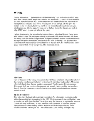
  • 1. Wiring Finally, some meat... I spent an entire day hand twisting 18ga stranded wire into 8' long pairs with various colors. Right side channels use Red as the (+) side, Left side channels use Blue. I created custom RCA cables and wired the amp to crossovers, crossovers to wiring harness, using the hand-rolled twisted pairs. It was a tough job that gave me 7 blisters on my two hands, but it was worth it! My system has absolutely no noise, no interference, and it looks great. Twisted pair is the best choice for the car. Just look at what BMW used - twisted pair all over the place. I wired the power for the amp directly from the battery using 8ga Monster Cable power wire. Thanks BMW for putting the battery in the trunk! This was a very easy job. I ran the wiring from the battery compartment, along the other two monster sized cables under the right trim panel in the trunk, and up under the deck to the amp. The ground wire is short and sheet-metal screwed to the underside of the rear deck. Be sure to use the same guage wire for both power and ground. This minimizes noise. Pin-Outs Here is the detail of the wiring connections I used. Please note that I only used a subset of the available pins because the factory system has 10 individual loudspeakers. My system effectively has 6 since the rear speakers are coaxial. This leaves the 2 front midrange drivers and the 2 rear tweeters disconnected and unused. I also wired the rear speakers directly from the crossovers, which leaves the rear woofer connections to the harness unused as well. 12-pin Connector This is the baby that delayed my project completion. No aftermarket companies make wiring harness interface connectors for the E39. All of my research showed that they may be coming out with them, but didn't have them now. So, it was up to me to make my own. I contacted Amp in Germany to get a matching male connector to interface with the female connector on the factory harness. Even in Silicon Valley I could not find a suitable connector for this job. So, I was on my own! After coming up empty, my
  • 2. colleague Sherman informed me that it's possible to get "samples" from component manufactures. So, I called Amp (see references section for contact info) and spoke with the designer of the part in the car. He gave me the part number for the matching connector and I ordered some samples. I did mention I needed the pins as well and assumed they'd be shipped with the connector, but with my luck they didn't arrive. Another call, another conversation, and the pins were on the way. Connections I used One thing I have to tell you is I'm colorblind. So, referring to the colors on the wires is not an option for me. I had a friend map the positions for me so I could do this without assistance. I provide the info I got from Willard Lee for your reference only. Be sure to double check all connections before you go with them. I used a digital voltmeter (DVM) with a tone setting to identify each speaker wire. 1 2 3 4 5 6 12 11 10 8 7 Pin Colors Used Yellow/Red Left Front Woofer (-) 1 Yellow/Brown Left Front Woofer (+) 2 Blue/Red Right Front Woofer (-) 3 Blue/Brown Right Front Woofer (+) 4 Yellow/Purple Left Rear Woofer (+) 5 Yellow/Grey Left Rear Woofer (-) 6 Blue/Grey Right Rear Woofer (-) 7 Blue/Purple Right Rear Woofer (+) 8 Blank 9
  • 3. Brown Ground (DO NOT USE) 10 White Remote Turn On Lead 11 Red Power (DO NOT USE) 12 26-pin Connector This was a little tricky. I manufactured my own 26 pin connector using the above mentioned 26-pin shrouded header. The pins are so close together that I had to solder on 6" solid core wire leads, then connect the stranded pairs to these leads. You're in for a treat doing this part. Use a pencil point soldering iron, isolate the bottom row of pins from the top row with something, and be sure to use shrink tubing around each individual connection to insulate them from eachother. I suggest buying a few extras in case you mess up. Also, be sure no solder dripped and connected two or more pins together. That would be really bad! When connecting RCA plugs to the harness remember that the center post on the RCA plug is the positive lead from the harness. 1 2 3 4 8 9 10 11 12 13 26 25 24 23 19 18 17 16 15 14 Pin Colors Used Brown/Orange Head Unit Right Rear Output (-) 1 Blue/Black Head Unit Right Rear Output (+) 2 Yellow/Black Head Unit Left Rear Output (+) 3 Brown/Orange Head Unit Left Rear Output (-) 4 5 6
  • 4. 7 Blue/White Right Front Mid (+) 8 Blue/Orange Right Front Mid (-) 9 Yellow/Black Left Rear Tweeter (+) 10 Yellow/Grey Left Rear Tweeter (-) 11 Blue/Black Right Rear Tweeter (+) 12 Blue/Grey Right Rear Tweeter (-) 13 Yellow/Brown Left Front Mid (-) 14 Yellow/White Left Front Mid (+) 15 Blue/Brown Right Front Tweeter (-) 16 Blue/Green Right Front Tweeter (+) 17 Yellow/Brown Left Front Tweeter (-) 18 Yellow/Green Left Front Tweeter (+) 19 20 21 22 Brown/Orange Head Unit Right Front Output (-) 23 Yellow/Red Head Unit Right Front Output (+) 24 Blue/Red Head Unit Left Front Output (+) 25
  • 5. Brown/Orange Head Unit Left Front Output (-) 26